air BMW X5 2000 E53 Level Control System Manual
[x] Cancel search | Manufacturer: BMW, Model Year: 2000, Model line: X5, Model: BMW X5 2000 E53Pages: 57, PDF Size: 1.89 MB
Page 1 of 57
Initial Print Date:3/02Revision Date:
Subject Page
Hydraulic Level Control System .........................................................
Air Suspension Systems (EHC) ...........................................................
Table of Contents
Level Control Systems
Page 3 of 57
3
Level Control Systems
Level Control Systems
Purpose of the System
The primary function of Level Control Systems is to maintain the height of the vehicle as
closely as possible to a predetermined level under all load conditions.
This constant level allows the suspension system to maintain the alignment geometry.
Camber and Toe in are minimally affected when the ride height is consistent. In addition,
the headlight range stays consistent throughout the various operating conditions.
The Level Control System is designed to operate in the event of static changes such as
when passengers are entering or exiting the vehicle or quasi-static such as s when the fuel
tank is emptying while driving.
The Level Control System come in various configurations such as hydraulic (hydropneu-
matic) or pneumatic only systems.
Hydropneumatic systems use high pressure hydraulic fluid which is dampened by a gas
cushion from a nitrogen charged accumulator. These system use and electro-hydraulic
pump or an engine driven piston pump. These systems are installed as follows:
Hydropneumatic Level Control System with electro-hydraulic pump- This
type of system is used on the early 5 Series vehicles (E12 and E28), the 6 Series
(E24) and the early 7 Series (E23). This system uses an electric motor, pump and
an expansion tank which is connected by hydraulic lines to the rear spring struts.
The rear spring struts are also connected to a pair of pressure accumulators which
are “Nitrogen Charged”. There is a control switch which mounted on the rear axle
which monitors the position of the stabilizer bar. Changes in ride height are detect-
ed and the system is regulated to maintain the correct level. During prolonged dyna-
mic movements during acceleration and braking, the level control system is disabled
by an acceleration sensor (mercury switch) and brake light input to the hydraulic
control unit.
Hydropneumatic Level Control System with engine driven piston pump- This
system can be found on the 7 Series (E32 and E38) and the 5 Series Touring (E34).
This configuration is similar in operation to the previous system with a few changes.
There hydraulic pressure now comes from an engine driven piston pump. This
pump is mounted in tandem with the power steering (radial type) pump. The pres-
surized fluid is sent to a control valve which distributes the fluid to the rear spring
struts and pressure accumulators. The control valve is attached to the rear sway
bar by a lever, changes in ride height will move the lever which will influence fluid flow
to the spring struts.
The next generation of BMW Level Control Systems evolved into pneumatic only systems
which are referred to as EHC. EHC will be discussed later in this module.
Page 13 of 57
13
Level Control Systems
Air Suspension Systems (EHC)
Purpose of the System
Air Suspension systems were first introduced on the 1999 E39 Sportwagon. Since then
the E53 (X5) and E65/E66 (7Series) models were available with this new system. EHC are
available is two configurations, the Single Axle Air Suspension System and the Dual Axle
Air Suspension System. The Dual Axle (EHC II) system is only available on E53 X5 models
from the 2002 model year.
EHC systems can be found on the following vehicles:
E39 Sportwagon 528i, 525i and 540i from the 1999 Model Year (Single Axle)
E53 X5 3.0i and 4.4i from the 2000 Model Year (Single Axle)
E53 X5 4.6iS from 2002 (Single Axle)
E53 X5 3.0i and 4.4i from 2002 (Dual Axle EHC II)
E65/E66 from 2003 Model Year (Single Axle)
There are some functional changes with these systems. On EHC, the entire axle load is
borne by the air suspension. The underlying control philosophy of EHC is “Control only
when absolutely necessary”. This means that brief changes in the ride height are not com-
pensated (such as potholes). This avoids any unnecessary control operations.
The advantages of air suspension are as follows:
Control is independent of the vehicle engine
Single-wheel control is possible
Lateral locking is affected
A distinction is made between load and drive states
An inclined load is identified and corrected
However, an inclination is not compensated
Self diagnosis can be performed
Diagnosis with DISplus or GT-1 is possible
An automatic interruption of control takes place in case of cornering and wheel
changes.
Page 14 of 57
14
Level Control Systems
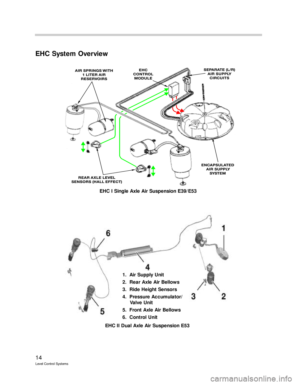
EHC System Overview
EHC I Single Axle Air Suspension E39/E53
EHC II Dual Axle Air Suspension E53
1. Air Supply Unit
2. Rear Axle Air Bellows
3. Ride Height Sensors
4. Pressure Accumulator/
Valve Unit
5. Front Axle Air Bellows
6. Control Unit
Page 15 of 57
15
Level Control Systems
Single Axle EHC I System Components (E39/E53)
The EHC system consists of the following components:
EHC Control Module
Air Springs (2) with Air Reservoirs
Rear Axle Level Sensors
Encapsulated Air Supply (LVA)
Warning Indicator
Control Module
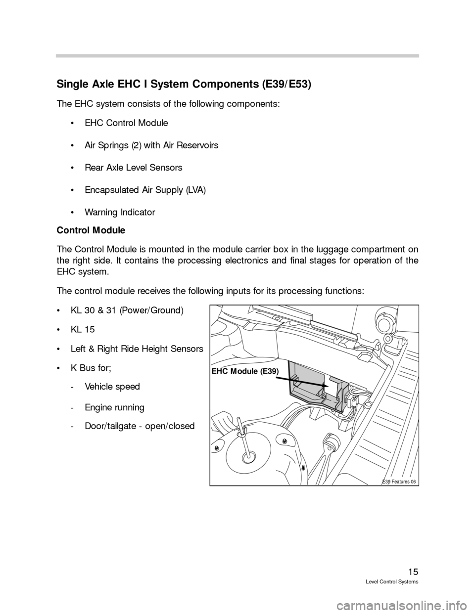
The Control Module is mounted in the module carrier box in the luggage compartment on
the right side. It contains the processing electronics and final stages for operation of the
EHC system.
The control module receives the following inputs for its processing functions:
KL 30 & 31 (Power/Ground)
KL 15
Left & Right Ride Height Sensors
K Bus for;
- Vehicle speed
- Engine running
- Door/tailgate - open/closed
E39 Features 06
EHC Module (E39)
Page 17 of 57
17
Level Control Systems
Air Springs
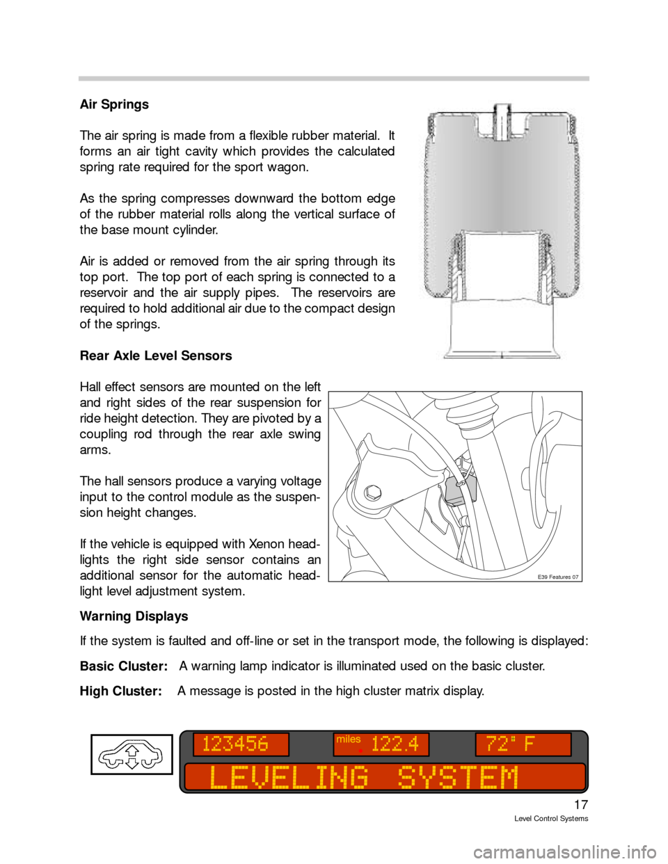
The air spring is made from a flexible rubber material. It
forms an air tight cavity which provides the calculated
spring rate required for the sport wagon.
As the spring compresses downward the bottom edge
of the rubber material rolls along the vertical surface of
the base mount cylinder.
Air is added or removed from the air spring through its
top port. The top port of each spring is connected to a
reservoir and the air supply pipes. The reservoirs are
required to hold additional air due to the compact design
of the springs.
Rear Axle Level Sensors
Hall effect sensors are mounted on the left
and right sides of the rear suspension for
ride height detection. They are pivoted by a
coupling rod through the rear axle swing
arms.
The hall sensors produce a varying voltage
input to the control module as the suspen-
sion height changes.
If the vehicle is equipped with Xenon head-
lights the right side sensor contains an
additional sensor for the automatic head-
light level adjustment system.
Warning Displays
If the system is faulted and off-line or set in the transport mode, the following is displayed:
Basic Cluster:A warning lamp indicator is illuminated used on the basic cluster.
High Cluster: A message is posted in the high cluster matrix display.
E39 Features 07
Page 18 of 57
18
Level Control Systems
Air Supply System (LVA)
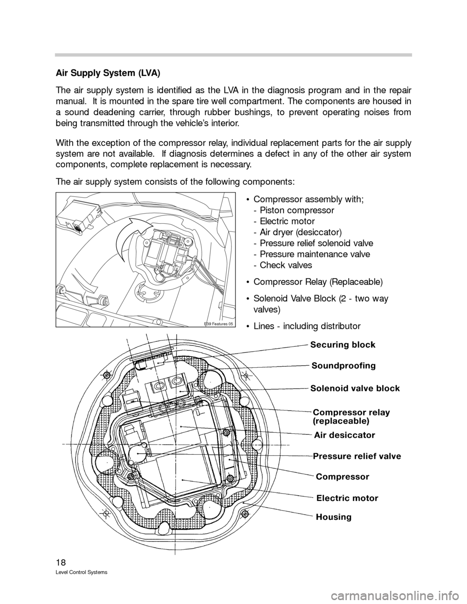
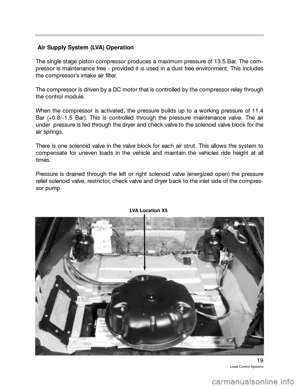
The air supply system is identified as the LVA in the diagnosis program and in the repair
manual. It is mounted in the spare tire well compartment. The components are housed in
a sound deadening carrier, through rubber bushings, to prevent operating noises from
being transmitted through the vehicle’s interior.
With the exception of the compressor relay, individual replacement parts for the air supply
system are not available. If diagnosis determines a defect in any of the other air system
components, complete replacement is necessary.
The air supply system consists of the following components:
Compressor assembly with;
- Piston compressor
- Electric motor
- Air dryer (desiccator)
- Pressure relief solenoid valve
- Pressure maintenance valve
- Check valves
Compressor Relay (Replaceable)
Solenoid Valve Block (2 - two way
valves)
Lines - including distributor
E39 Features 05
Page 19 of 57
19
Level Control Systems
Air Supply System (LVA) Operation
The single stage piston compressor produces a maximum pressure of 13.5 Bar. The com-
pressor is maintenance free - provided it is used in a dust free environment. This includes
the compressor’s intake air filter.
The compressor is driven by a DC motor that is controlled by the compressor relay through
the control module.
When the compressor is activated, the pressure builds up to a working pressure of 11.4
Bar (+0.8/-1.5 Bar). This is controlled through the pressure maintenance valve. The air
under pressure is fed through the dryer and check valve to the solenoid valve block for the
air springs.
There is one solenoid valve in the valve block for each air strut. This allows the system to
compensate for uneven loads in the vehicle and maintain the vehicles ride height at all
times.
Pressure is drained through the left or right solenoid valve (energized open) the pressure
relief solenoid valve, restrictor, check valve and dryer back to the inlet side of the compres-
sor pump.
LVA Location X5
Page 23 of 57
23
Level Control Systems
Special Operating Modes
Assembly Line Mode (New control module)
The assembly line mode refers to control module manufacturing. New control modules
are stored in a deactivated state. The control programming is not active and must first
be ZCS encoded.
After installing a replacement control module, it must be coded using the DIS or MoDiC.
The instrument cluster fault display will remain illuminated until the control module is
coded.
Transport Mode
The vehicle rolls off the factory assembly line with the EHC control module in the trans-
port mode. The transport mode inflates the air springs to a higher position (approx.
30mm higher) than the normal mode in order to avoid damage during transit.
The system will not respond to any inputs that would alter the height of the vehicle. The
fault indicator (base cluster) is illuminated or instrument cluster matrix display (high clus-
ter) provides the message “Leveling System” to draw attention to the transport mode
setting.
The Service Functions section of the diagnosis program is used to activate/deactivate
the transport mode. Once the transport mode is deactivated, check the vehicle Ride
Height Offset making sure the vehicle rear axle height is to specification.
Control Interrupts
Cornering
To prevent unnecessary suspension adjustments while driving through corners, a “control
interrupt” is built into the system. Above 30MPH the control module monitors the left/right
ride height sensors for a difference of 30mm. Exceeding this difference will put the system
into a control interrupt and no adjustment will take place. The control interrupt last for a
duration of 5 minutes.
Vehicle Lifting
The ride height control is interrupted when the vehicle is raised on a lift or with a jack. The
system monitors the ride height sensor inputs and when the height limit of 90 mm is
exceeded, the control is switched OFF until the vehicle is lowered again.
Page 26 of 57
26
Level Control Systems
TIS Repair Manual Information
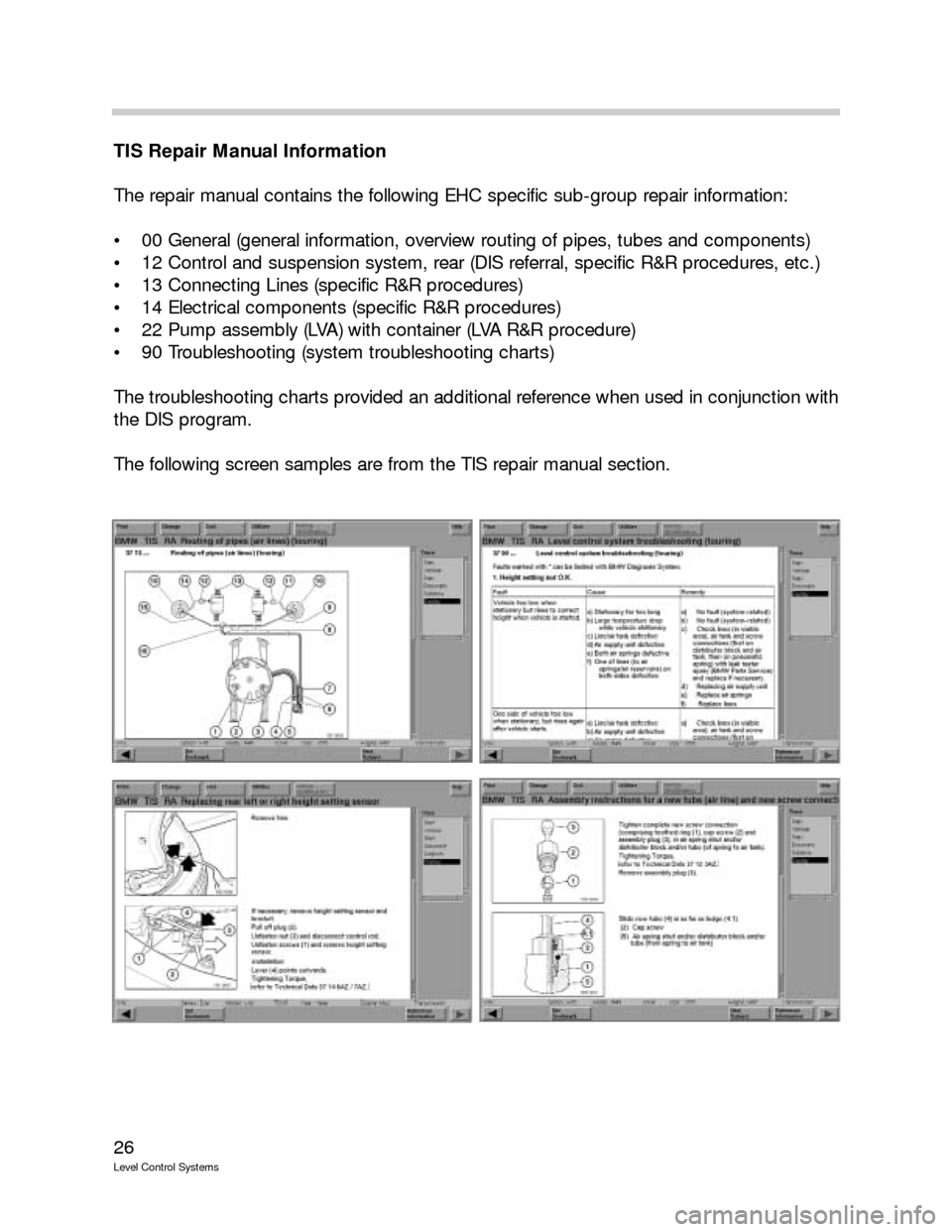
The repair manual contains the following EHC specific sub-group repair information:
00 General (general information, overview routing of pipes, tubes and components)
12 Control and suspension system, rear (DIS referral, specific R&R procedures, etc.)
13 Connecting Lines (specific R&R procedures)
14 Electrical components (specific R&R procedures)
22 Pump assembly (LVA) with container (LVA R&R procedure)
90 Troubleshooting (system troubleshooting charts)
The troubleshooting charts provided an additional reference when used in conjunction with
the DIS program.
The following screen samples are from the TIS repair manual section.