crankshaft BMW X5 2002 E53 M54 Engine Workshop Manual
[x] Cancel search | Manufacturer: BMW, Model Year: 2002, Model line: X5, Model: BMW X5 2002 E53Pages: 48, PDF Size: 2.52 MB
Page 1 of 48
Initial Print Date: 02/2000Revision Date: 6/2000
Subject Page
M54 Engine
Introduction . . . . . . . . . . . . . . . . . . . . . . . . . . . . . . . . . . . . . . . . . . . . . . . . . 2
Mechanical changes . . . . . . . . . . . . . . . . . . . . . . . . . . . . . . . . . . . . . . . . . . . . 4
Performance Charts . . . . . . . . . . . . . . . . . . . . . . . . . . . . . . . . . . . . . . . . . . . . 6
Review Questions. . . . . . . . . . . . . . . . . . . . . . . . . . . . . . . . . . . . . . . . . . . . . . 7
Siemen’s MS 43.0 System
• Introduction . . . . . . . . . . . . . . . . . . . . . . . . . . . . . . . . . . . . . . . . . . . . . . 8
• I - P - O . . . . . . . . . . . . . . . . . . . . . . . . . . . . . . . . . . . . . . . . . . . . . . . . 9
MS 43.0 New functions
• Electronic throttle Control . . . . . . . . . . . . . . . . . . . . . . . . . . . . . . . . . .10
• Accelerator Pedal Sensor (PWG) . . . . . . . . . . . . . . . . . . . . . . . . . . . . .11
• Electronic Throttle Valve (EDK) . . . . . . . . . . . . . . . . . . . . . . . . . . . . . .13
• Main Relay Monitor . . . . . . . . . . . . . . . . . . . . . . . . . . . . . . . . . . . . . . . .15
• Engine Optimized Ignition Key OFF . . . . . . . . . . . . . . . . . . . . . . . . . . . .16
• Diagnosis Module Tank Leakage (DM-TL) . . . . . . . . . . . . . . . . . . . . . . .17
• DM-TL Function . . . . . . . . . . . . . . . . . . . . . . . . . . . . . . . . . . . . . . . . . .18
• DM-TL Test Procedure . . . . . . . . . . . . . . . . . . . . . . . . . . . . . . . . . . . . .20
Carry Over Functions
Inputs
• Oxygen Sensor . . . . . . . . . . . . . . . . . . . . . . . . . . . . . . . . . . . . . . . . . .25
• Camshaft Sensors . . . . . . . . . . . . . . . . . . . . . . . . . . . . . . . . . . . . . . . .26
• Crankshaft Sensor . . . . . . . . . . . . . . . . . . . . . . . . . . . . . . . . . . . . . . . .27
• Misfire Detection . . . . . . . . . . . . . . . . . . . . . . . . . . . . . . . . . . . . . . . . .28
• OBD Fault Codes . . . . . . . . . . . . . . . . . . . . . . . . . . . . . . . . . . . . . . . .30
• Mass Air Meter . . . . . . . . . . . . . . . . . . . . . . . . . . . . . . . . . . . . . . . . . .31
Outputs
• VANOS Control . . . . . . . . . . . . . . . . . . . . . . . . . . . . . . . . . . . . . . . . . .33
• Electric Fan . . . . . . . . . . . . . . . . . . . . . . . . . . . . . . . . . . . . . . . . . . . . .36
• Secondary Air Injection . . . . . . . . . . . . . . . . . . . . . . . . . . . . . . . . . . . .37
• Engine Speed Limit . . . . . . . . . . . . . . . . . . . . . . . . . . . . . . . . . . . . . . .39
• RZV Ignition . . . . . . . . . . . . . . . . . . . . . . . . . . . . . . . . . . . . . . . . . . . .40
• Resonance - Turbulence Manifold . . . . . . . . . . . . . . . . . . . . . . . . . . . .42
• Idle Speed control . . . . . . . . . . . . . . . . . . . . . . . . . . . . . . . . . . . . . . . .45
• Cruise Control . . . . . . . . . . . . . . . . . . . . . . . . . . . . . . . . . . . . . . . . . . .46
• Purge Control . . . . . . . . . . . . . . . . . . . . . . . . . . . . . . . . . . . . . . . . . . . .47
Table of Contents
Page 4 of 48
M54 ENGINE
Mechanical Changes
In addition to the increased displacement of the M54B30 engine, several mechanical
changes were incorporated into the engine for reduced emissions and increased fuel econ-
omy. These changes include:
• NEW PISTONS - The piston has a shorter skirt compared to the M52 TU and continues
with the graphite coating for friction and emission reducing measures. The piston rings have
been modified to reduce friction.
• CRANKSHAFT - The crankshaft for the 3 liter M54 is adopted from the S52B32 - M3
engine.
• CAMSHAFT - The camshaft for the 3 liter M54 is modified with more lift (9.7 mm) and
new valve springs to accommodate the increased lift.
• INTAKE MANIFOLD - The intake manifold is modified with shorter ram tubes (20mm
shorter on 3 liter. The diameter of the tubes is increased slightly.
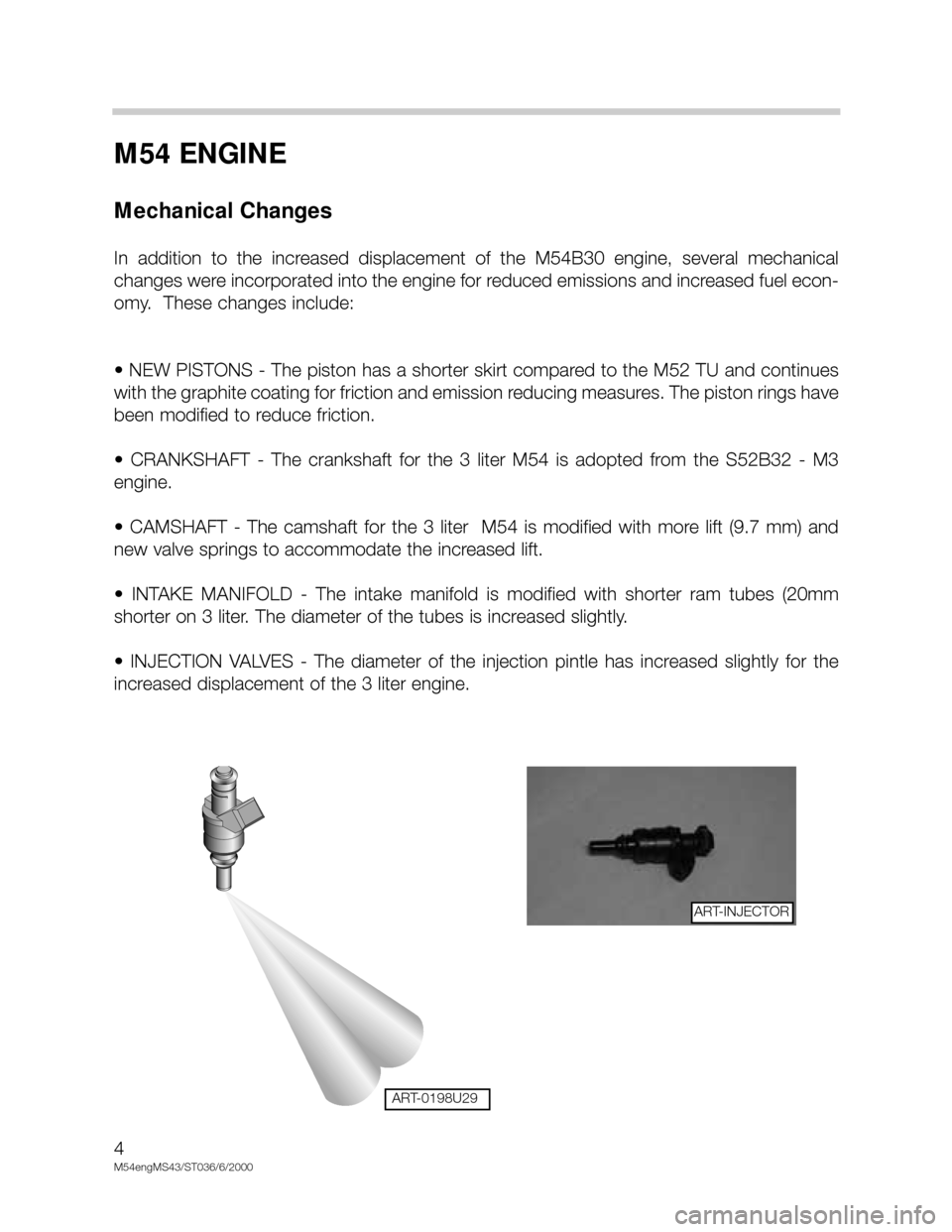
• INJECTION VALVES - The diameter of the injection pintle has increased slightly for the
increased displacement of the 3 liter engine.
4
M54engMS43/ST036/6/2000
ART-0198U29
ART-INJECTOR
Page 26 of 48
26
M54engMS43/ST036/6/2000
CAMSHAFT SENSOR
-INTAKE AND EXHAUST CAMSHAFTS
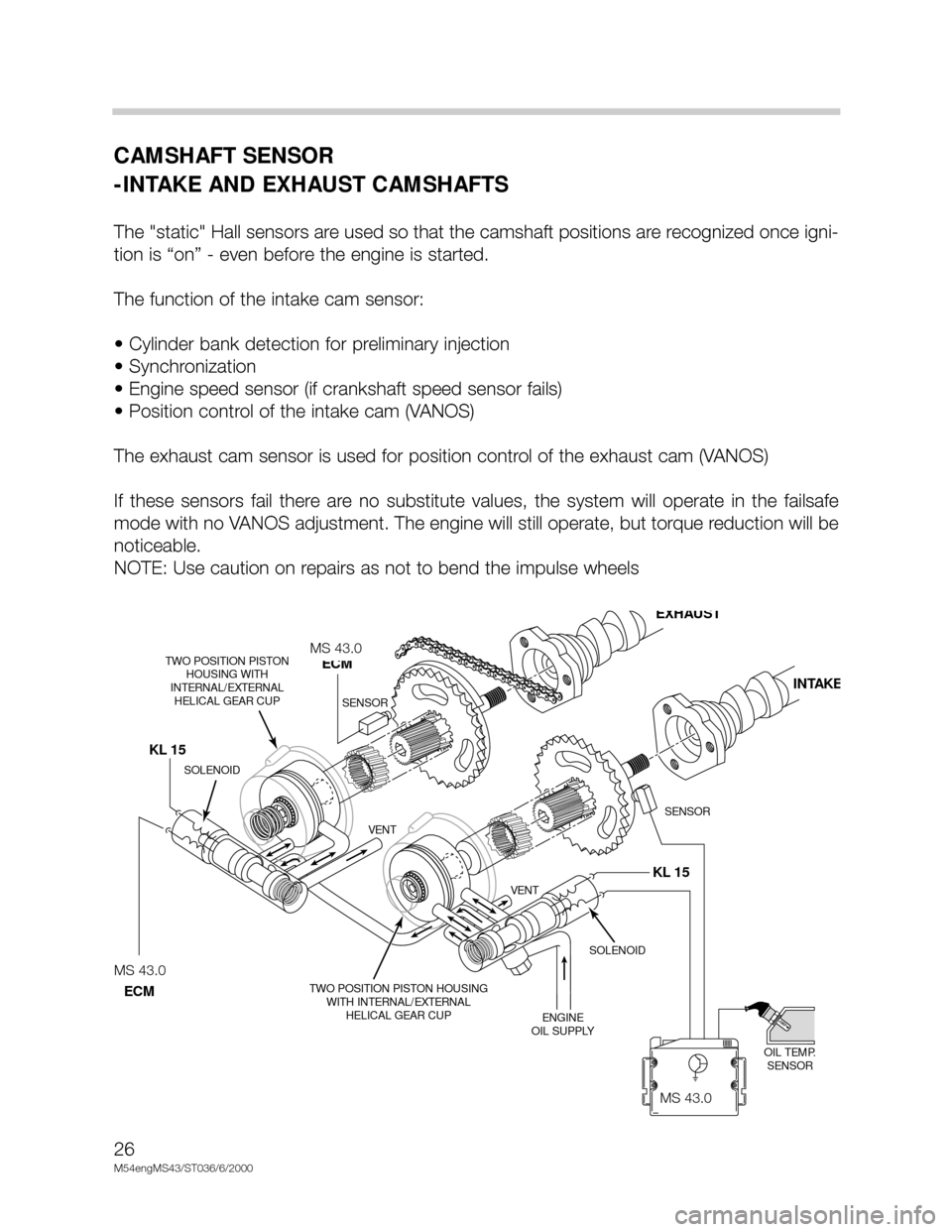
The "static" Hall sensors are used so that the camshaft positions are recognized once igni-
tion is “on” - even before the engine is started.
The function of the intake cam sensor:
• Cylinder bank detection for preliminary injection
• Synchronization
• Engine speed sensor (if crankshaft speed sensor fails)
• Position control of the intake cam (VANOS)
The exhaust cam sensor is used for position control of the exhaust cam (VANOS)
If these sensors fail there are no substitute values, the system will operate in the failsafe
mode with no VANOS adjustment. The engine will still operate, but torque reduction will be
noticeable.
NOTE: Use caution on repairs as not to bend the impulse wheels
KL 15 KL 15
MS42.0
SOLENOID
OIL TEMP.
SENSOR TWO POSITION PISTON HOUSING
WITH INTERNAL/EXTERNAL
HELICAL GEAR CUP TWO POSITION PISTON
HOUSING WITH
INTERNAL/EXTERNAL
HELICAL GEAR CUP
ENGINE
OIL SUPPLY VENT VENT
SOLENOID
SENSOR SENSOR
MS42
ECM
EXHAUST
INTAKE
MS42.0
ECM
MS 43.0
MS 43.0
MS 43.0
Page 27 of 48
27
M54engMS43/ST036/6/20000
CRANKSHAFT SENSOR
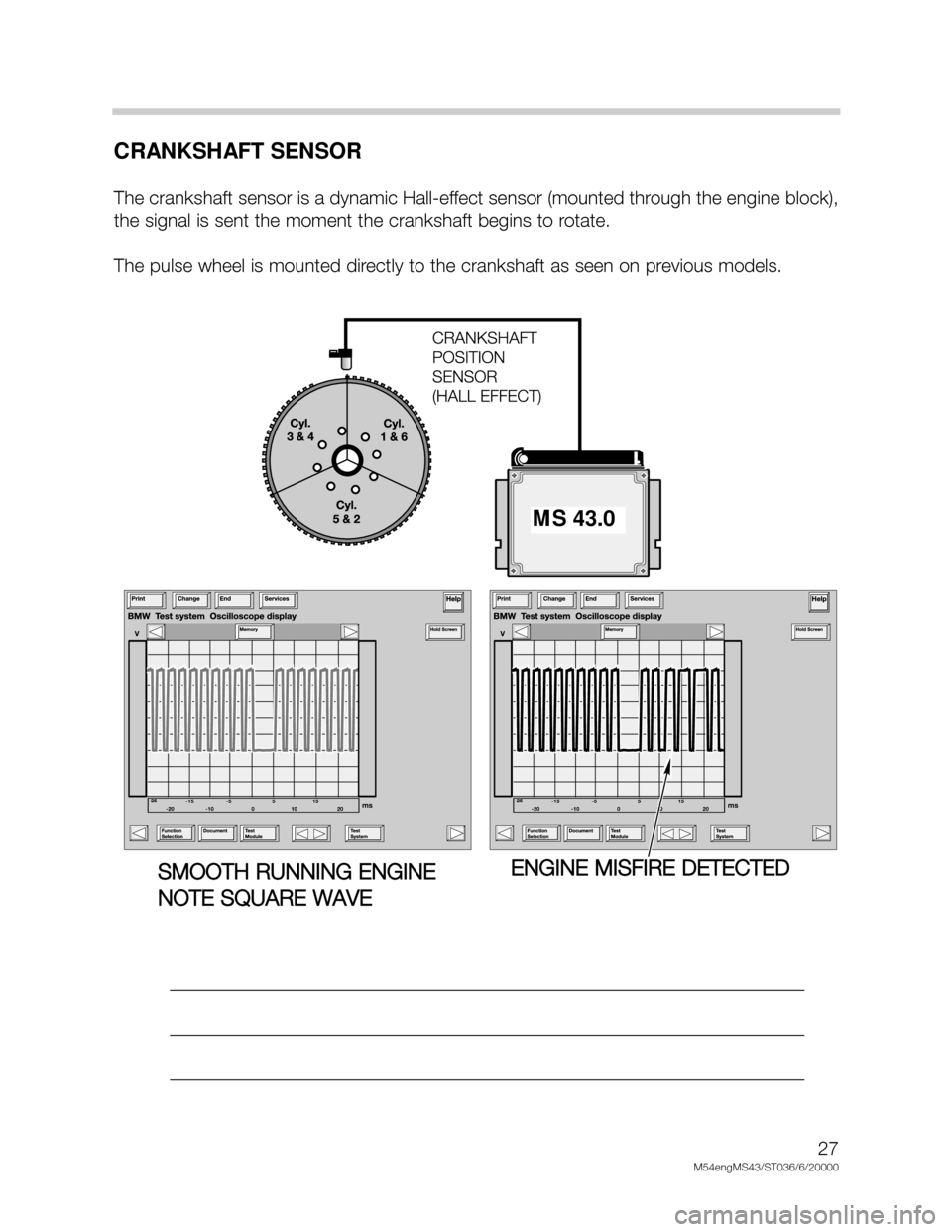
The crankshaft sensor is a dynamic Hall-effect sensor (mounted through the engine block),
the signal is sent the moment the crankshaft begins to rotate.
The pulse wheel is mounted directly to the crankshaft as seen on previous models.
____________________________________________________________________
____________________________________________________________________
____________________________________________________________________
MS 43.0
SMOOTH RUNNING ENGINE
NOTE SQUARE WAVEENGINE MISFIRE DETECTED
Page 28 of 48

28
M54engMS43/ST036/6/2000
MISFIRE DETECTION
As part of the CARB/OBD regulations the engine control module must determine if misfire
is occurring and also identify the specific cylinder(s) and the severity of the misfire event,
and whether it is emissions relevant or catalyst damaging. In order to accomplish these
tasks the control module monitors the crankshaft for acceleration losses during firing seg-
ments of each cylinder based on firing order.
Misfire Detection Example: M54 (6 Cyl.) with Siemens System
The misfire/engine roughness calculation is derived from the differences in the period dura-
tion (T) of individual increment gear segments. Each segment period consist of an angular
range of 120° crank angle that starts 78° before Top Dead Center (TDC).
If the expected period duration is greater than the permissible value a misfire fault for the
particular cylinder is stored in the fault memory of the ECM. Depending on the level of mis-
fire rate measured the control unit will illuminate the "Service Engine Soon" light, may cut-
off fuel to the particular cylinder and may switch lambda operation to open-loop. All mis-
fire faults are weighted to determine if the misfire is emissions relevant or catalyst damag-
ing.
_________________________________________________________________
_________________________________________________________________
_________________________________________________________________
_________________________________________________________________
_________________________________________________________________
_________________________________________________________________
_________________________________________________________________
_________________________________________________________________
_________________________________________________________________
Page 29 of 48
29
M54engMS43/ST036/6/20000
EMISSIONS RELEVANT:
During an interval of 1000 crankshaft revolutions
the misfire events of all cylinders are
added and if the sum is greater than a predetermined value a fault will be set identifying the
particular cylinder(s). The “Service Engine Soon” light will be illuminated during and after
the second cycle if the fault is again present.
CATALYST DAMAGING:
During an interval of 200 crankshaft revolutions
the misfire events of all cylinders are added
and if the sum is greater than a predetermined value a fault will be set identifying the par-
ticular cylinders(s). The “Service Engine Soon” lamp:
• On vehicles with a Siemens Control Module (M54 engines) - the lamp will immediately go
to a steady illumination since fuel to the injector(s) is removed. Fuel cut-off to the cylin-
der will resume after several (
>>7) periods of decel if crankshaft sensor adaptation is suc-
cessfully completed or the engine is shut-off and restarted.
In each case the number of misfire events permitted is dependent on engine speed, load
and temperature map.
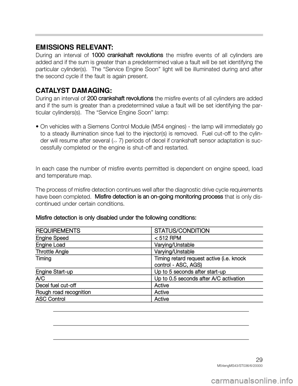
The process of misfire detection continues well after the diagnostic drive cycle requirements
have been completed. Misfire detection is an on-going monitoring process
that is only dis-
continued under certain conditions.
Misfire detection is only disabled under the following conditions:
___________________________________________________________________
___________________________________________________________________
___________________________________________________________________
REQUIREMENTSSTATUS/CONDITION
Engine Speed< 512 RPM
Engine LoadVarying/Unstable
Throttle AngleVarying/Unstable
TimingTiming retard request active (i.e. knock
control - ASC, AGS)
Engine Start-upUp to 5 seconds after start-up
A/CUp to 0.5 seconds after A/C activation
Decel fuel cut-offActive
Rough road recognitionActive
ASC ControlActive