Engine BMW X5 2011 E70 Owner's Guide
[x] Cancel search | Manufacturer: BMW, Model Year: 2011, Model line: X5, Model: BMW X5 2011 E70Pages: 312, PDF Size: 8.91 MB
Page 80 of 312
Controls Overview
78
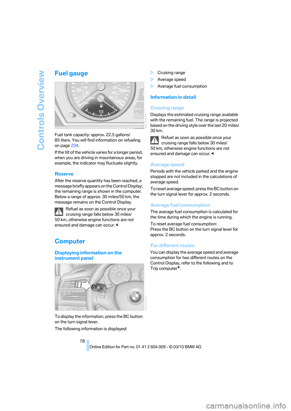
Fuel gauge
Fuel tank capacity: approx. 22.5 gallons/
85 liters. You will find information on refueling
on page234.
If the tilt of the vehicle varies for a longer period,
when you are driving in mountainous areas, for
example, the indicator may fluctuate slightly.
Reserve
After the reserve quantity has been reached, a
message briefly appears on the Control Display;
the remaining range is shown in the computer.
Below a range of approx. 30 miles/50 km, the
message remains on the Control Display.
Refuel as soon as possible once your
cruising range falls below 30 miles/
50 km, otherwise engine functions are not
ensured and damage can occur.<
Computer
Displaying information on the
instrument panel
To display the information, press the BC button
on the turn signal lever.
The following information is displayed:>Cruising range
>Average speed
>Average fuel consumption
Information in detail
Cruising range
Displays the estimated cruising range available
with the remaining fuel. The range is projected
based on the driving style over the last 20 miles/
30 km.
Refuel as soon as possible once your
cruising range falls below 30 miles/
50 km, otherwise engine functions are not
ensured and damage can occur.<
Average speed
Periods with the vehicle parked and the engine
stopped are not included in the calculations of
average speed.
To reset average speed: press the BC button on
the turn signal lever for approx. 2 seconds.
Average fuel consumption
The average fuel consumption is calculated for
the time during which the engine is running.
To reset average fuel consumption:
Press the BC button on the turn signal lever for
approx. 2 seconds.
For different routes
You can display the average speed and average
consumption for two different routes on the
Control Display, refer to the following and to
Trip computer
*.
Page 83 of 312
Controls
81Reference
At a glance
Driving tips
Communications
Navigation
Entertainment
Mobility
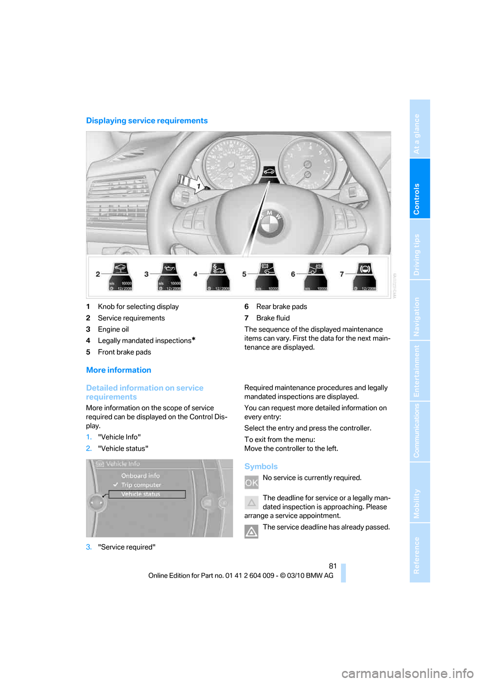
Displaying service requirements
1Knob for selecting display
2Service requirements
3Engine oil
4Legally mandated inspections
*
5Front brake pads6Rear brake pads
7Brake fluid
The sequence of the displayed maintenance
items can vary. First the data for the next main-
tenance are displayed.
More information
Detailed information on service
requirements
More information on the scope of service
required can be displayed on the Control Dis-
play.
1."Vehicle Info"
2."Vehicle status"
3."Service required"Required maintenance procedures and legally
mandated inspections are displayed.
You can request more detailed information on
every entry:
Select the entry and press the controller.
To exit from the menu:
Move the controller to the left.
Symbols
No service is currently required.
The deadline for service or a legally man-
dated inspection is approaching. Please
arrange a service appointment.
The service deadline has already passed.
Page 90 of 312
Technology for comfort, convenience and safety
88
Technology for comfort, convenience and
safety
PDC Park Distance Control*
The concept
In addition to the PDC Park Distance Control,
the rear view camera
*, refer to page93, can
also be switched on.
PDC assists you during parking. A slow
approach to an object in front of or behind your
vehicle is announced by:
>Signal tones
>Optical displays
Measurement
Ultrasonic sensors in the bumpers carry out the
measurement.
Their range is approx. 7 ft/2 m.
The acoustic warning begins:
>At approx. 24 in/60 cm for the front
* sen-
sors and the two rear corner sensors.
>At approx. 5 ft/1.50 m for the middle sen-
sors in the rear.
System limitations
PDC cannot replace the personal assess-
ment of the traffic situation. Also make a
direct visual check of the traffic situation around
the vehicle. Otherwise, there could be a risk of
accident, for example due to other road users or
objects outside the detection range of PDC.
Loud sources of sound, inside and outside the
vehicle, could drown out the PDC signal tone.<
Avoid approaching an object too quickly.
Avoid starting off quickly while PDC is not
yet activated.
Otherwise, physical circumstances could cause
the system to issue a warning late.<
Limitations of ultrasonic measurement
The detection of objects can come up against
the limitations of physical ultrasonic measure-
ment, for example:
>When using tow bars and towing hitches
>In the presence of thin or wedge-shaped
objects
>In the presence of low objects
>In the presence of objects with corners and
sharp edges
Low objects that have already been displayed,
e.g. curbs, can disappear again from the detec-
tion area of the sensors before or after a contin-
uous tone sounds.
Higher, protruding objects, e.g. ledges, cannot
be detected.
False warnings
Under the following conditions, PDC may dis-
play a warning even though no obstacle is
present in the detection range:
>In heavy rain
>When the sensors are heavily soiled or iced-
over
>When the sensors are covered with snow
>On rough road surfaces
>In large, rectangular buildings with smooth
walls, e.g. underground garages
>In the presence of heavy exhaust
>Due to the presence of other ultrasonic
sources such as street sweepers, steam
cleaners, or neon lamps.
Automatic activation
With the engine running or the ignition switched
on, shift the selector lever into position R.
Automatic deactivation
The system switches off and the LED goes out:
Page 92 of 312
Technology for comfort, convenience and safety
90
Malfunction
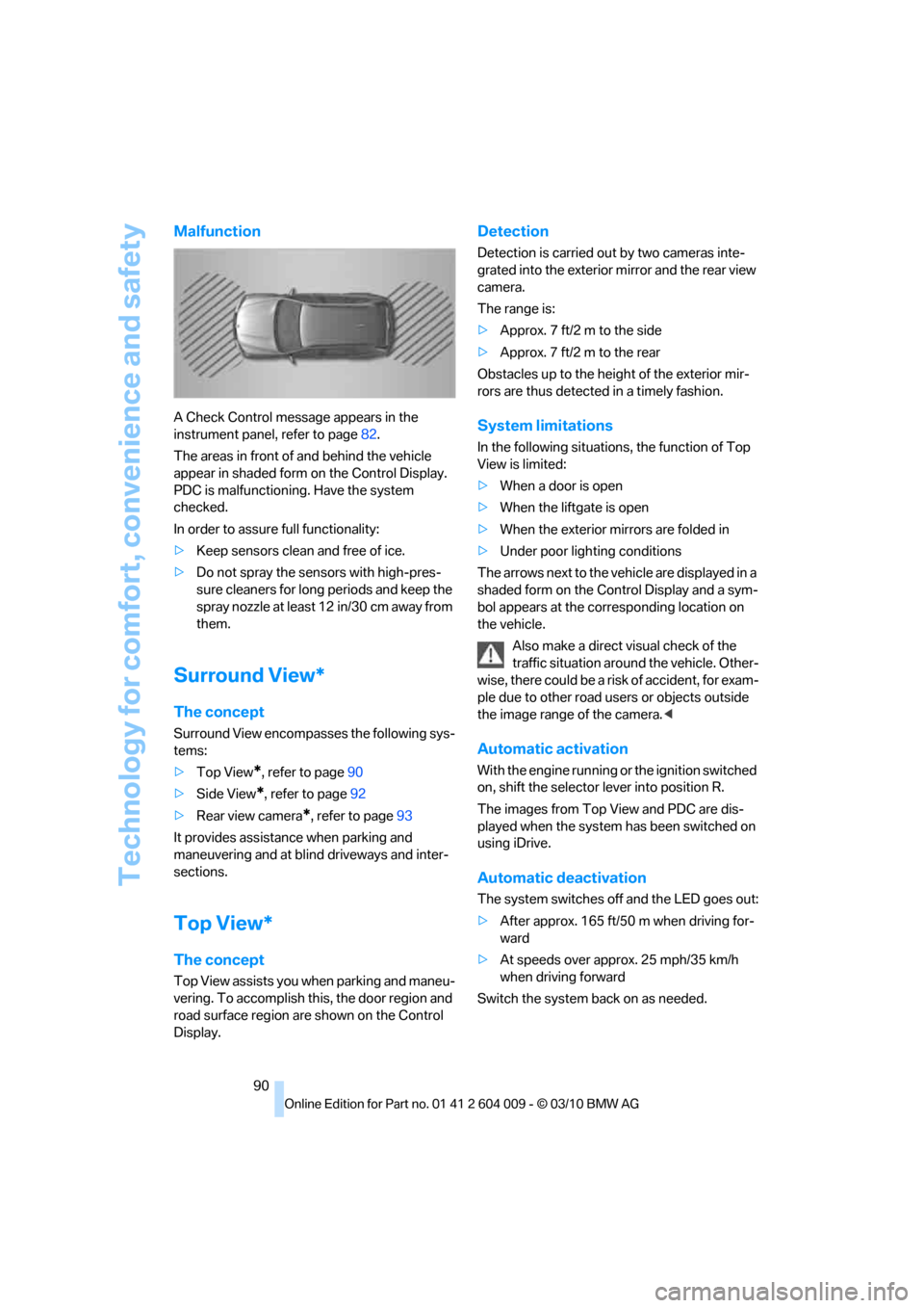
A Check Control message appears in the
instrument panel, refer to page82.
The areas in front of and behind the vehicle
appear in shaded form on the Control Display.
PDC is malfunctioning. Have the system
checked.
In order to assure full functionality:
>Keep sensors clean and free of ice.
>Do not spray the sensors with high-pres-
sure cleaners for long periods and keep the
spray nozzle at least 12 in/30 cm away from
them.
Surround View*
The concept
Surround View encompasses the following sys-
tems:
>Top View
*, refer to page90
>Side View
*, refer to page92
>Rear view camera
*, refer to page93
It provides assistance when parking and
maneuvering and at blind driveways and inter-
sections.
Top View*
The concept
Top View assists you when parking and maneu-
vering. To accomplish this, the door region and
road surface region are shown on the Control
Display.
Detection
Detection is carried out by two cameras inte-
grated into the exterior mirror and the rear view
camera.
The range is:
>Approx. 7 ft/2 m to the side
>Approx. 7 ft/2 m to the rear
Obstacles up to the height of the exterior mir-
rors are thus detected in a timely fashion.
System limitations
In the following situations, the function of Top
View is limited:
>When a door is open
>When the liftgate is open
>When the exterior mirrors are folded in
>Under poor lighting conditions
The arrows next to the vehicle are displayed in a
shaded form on the Control Display and a sym-
bol appears at the corresponding location on
the vehicle.
Also make a direct visual check of the
traffic situation around the vehicle. Other-
wise, there could be a risk of accident, for exam-
ple due to other road users or objects outside
the image range of the camera.<
Automatic activation
With the engine running or the ignition switched
on, shift the selector lever into position R.
The images from Top View and PDC are dis-
played when the system has been switched on
using iDrive.
Automatic deactivation
The system switches off and the LED goes out:
>After approx. 165 ft/50 m when driving for-
ward
>At speeds over approx. 25 mph/35 km/h
when driving forward
Switch the system back on as needed.
Page 95 of 312
Controls
93Reference
At a glance
Driving tips
Communications
Navigation
Entertainment
Mobility
Cameras
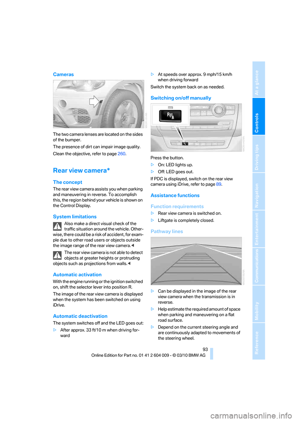
The two camera lenses are located on the sides
of the bumper.
The presence of dirt can impair image quality.
Clean the objective, refer to page260.
Rear view camera*
The concept
The rear view camera assists you when parking
and maneuvering in reverse. To accomplish
this, the region behind your vehicle is shown on
the Control Display.
System limitations
Also make a direct visual check of the
traffic situation around the vehicle. Other-
wise, there could be a risk of accident, for exam-
ple due to other road users or objects outside
the image range of the rear view camera.<
T he r e a r v i e w c a m e r a i s n o t a b l e t o de t e c t
objects at greater heights or protruding
objects such as projections from walls.<
Automatic activation
With the engine running or the ignition switched
on, shift the selector lever into position R.
The image of the rear view camera is displayed
when the system has been switched on using
iDrive.
Automatic deactivation
The system switches off and the LED goes out:
>After approx. 33 ft/10 m when driving for-
ward>At speeds over approx. 9 mph/15 km/h
when driving forward
Switch the system back on as needed.
Switching on/off manually
Press the button.
>On: LED lights up.
>Off: LED goes out.
If PDC is displayed, switch on the rear view
camera using iDrive, refer to page89.
Assistance functions
Function requirements
>Rear view camera is switched on.
>Liftgate is completely closed.
Pathway lines
>Can be displayed in the image of the rear
view camera when the transmission is in
reverse.
>Help estimate the required amount of space
when parking and maneuvering on a flat
road surface.
>Depend on the current steering angle and
are continuously adapted to movements of
the steering wheel.
Page 97 of 312
Controls
95Reference
At a glance
Driving tips
Communications
Navigation
Entertainment
Mobility
Three-dimensionally-shaped markings are dis-
played.
Image on the Control Display
Switching on the rear view camera
using iDrive
With PDC activated:
1.Select the "Rear view camera" symbol.
2.Press the controller.
The image of the rear view camera is displayed.
The setting is stored for the remote control cur-
rently in use.
Brightness
With the rear view camera switched on:
1.Select the symbol.
2.Turn the controller until the desired setting
is displayed and then press the controller.
Contrast
With the rear view camera switched on:
1.Select the symbol.
2.Turn the controller until the desired setting
is displayed and then press the controller.
Camera
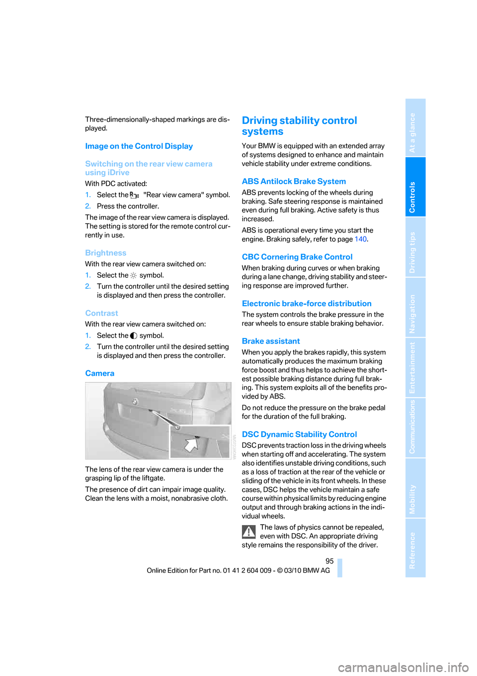
The lens of the rear view camera is under the
grasping lip of the liftgate.
The presence of dirt can impair image quality.
Clean the lens with a moist, nonabrasive cloth.
Driving stability control
systems
Your BMW is equipped with an extended array
of systems designed to enhance and maintain
vehicle stability under extreme conditions.
ABS Antilock Brake System
ABS prevents locking of the wheels during
braking. Safe steering response is maintained
even during full braking. Active safety is thus
increased.
ABS is operational every time you start the
engine. Braking safely, refer to page140.
CBC Cornering Brake Control
When braking during curves or when braking
during a lane change, driving stability and steer-
ing response are improved further.
Electronic brake-force distribution
The system controls the brake pressure in the
rear wheels to ensure stable braking behavior.
Brake assistant
When you apply the brakes rapidly, this system
automatically produces the maximum braking
force boost and thus helps to achieve the short-
est possible braking distance during full brak-
ing. This system exploits all of the benefits pro-
vided by ABS.
Do not reduce the pressure on the brake pedal
for the duration of the full braking.
DSC Dynamic Stability Control
DSC prevents traction loss in the driving wheels
when starting off and accelerating. The system
also identifies unstable driving conditions, such
as a loss of traction at the rear of the vehicle or
sliding of the vehicle in its front wheels. In these
cases, DSC helps the vehicle maintain a safe
course within physical limits by reducing engine
output and through braking actions in the indi-
vidual wheels.
The laws of physics cannot be repealed,
even with DSC. An appropriate driving
style remains the responsibility of the driver.
Page 102 of 312
Technology for comfort, convenience and safety
100
Function requirements
The system must have been initialized while the
tire inflation pressure was correct; otherwise,
reliable signaling of a flat tire is not ensured.
Initialize the system after every correction of the
tire inflation pressure and after every tire or
wheel change.
System limits
Sudden serious tire damage caused by
external influences cannot be indicated in
advance.<
A natural, even pressure loss in all four tires
cannot be detected. Therefore, check the tire
inflation pressure regularly.
In the following situations, the system could be
delayed or malfunction:
>System has not been initialized
>Driving on snowy or slippery road surface
>Sporty driving style: slip in the drive wheels,
high lateral acceleration
>Driving with snow chains
*
When you are driving with the compact wheel*
the Flat Tire Monitor is unable to function.
Status display
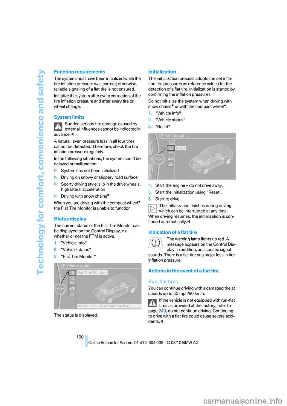
The current status of the Flat Tire Monitor can
be displayed on the Control Display, e.g.
whether or not the FTM is active.
1."Vehicle Info"
2."Vehicle status"
3."Flat Tire Monitor"
The status is displayed.
Initialization
The initialization process adopts the set infla-
tion tire pressures as reference values for the
detection of a flat tire. Initialization is started by
confirming the inflation pressures.
Do not initialize the system when driving with
snow chains
* or with the compact wheel*.
1."Vehicle Info"
2."Vehicle status"
3."Reset"
4.Start the engine – do not drive away.
5.Start the initialization using "Reset".
6.Start to drive.
The initialization finishes during driving,
which can be interrupted at any time.
When driving resumes, the initialization is con-
tinued automatically.<
Indication of a flat tire
The warning lamp lights up red. A
message appears on the Control Dis-
play. In addition, an acoustic signal
sounds. There is a flat tire or a major loss in tire
inflation pressure.
Actions in the event of a flat tire
Run-flat tires
You can continue driving with a damaged tire at
speeds up to 50 mph/80 km/h.
If the vehicle is not equipped with run-flat
tires as provided at the factory, refer to
page249, do not continue driving. Continuing
to drive with a flat tire could cause severe acci-
dents.<
Page 104 of 312
Technology for comfort, convenience and safety
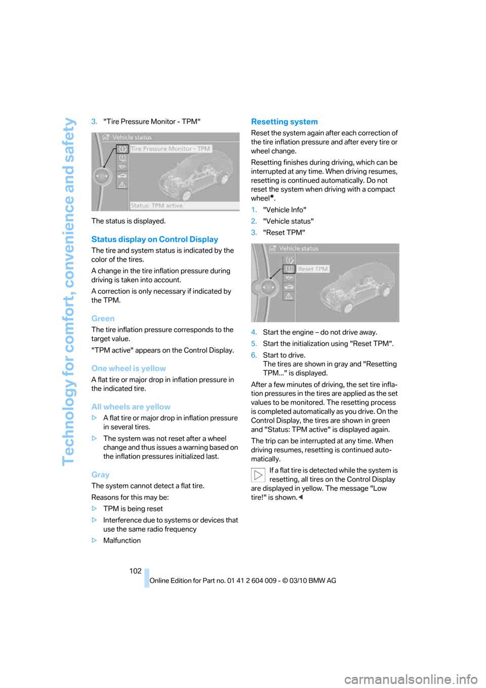
102 3."Tire Pressure Monitor - TPM"
The status is displayed.
Status display on Control Display
The tire and system status is indicated by the
color of the tires.
A change in the tire inflation pressure during
driving is taken into account.
A correction is only necessary if indicated by
the TPM.
Green
The tire inflation pressure corresponds to the
target value.
"TPM active" appears on the Control Display.
One wheel is yellow
A flat tire or major drop in inflation pressure in
the indicated tire.
All wheels are yellow
>A flat tire or major drop in inflation pressure
in several tires.
>The system was not reset after a wheel
change and thus issues a warning based on
the inflation pressures initialized last.
Gray
The system cannot detect a flat tire.
Reasons for this may be:
>TPM is being reset
>Interference due to systems or devices that
use the same radio frequency
>Malfunction
Resetting system
Reset the system again after each correction of
the tire inflation pressure and after every tire or
wheel change.
Resetting finishes during driving, which can be
interrupted at any time. When driving resumes,
resetting is continued automatically. Do not
reset the system when driving with a compact
wheel
*.
1."Vehicle Info"
2."Vehicle status"
3."Reset TPM"
4.Start the engine – do not drive away.
5.Start the initialization using "Reset TPM".
6.Start to drive.
The tires are shown in gray and "Resetting
TPM..." is displayed.
After a few minutes of driving, the set tire infla-
tion pressures in the tires are applied as the set
values to be monitored. The resetting process
is completed automatically as you drive. On the
Control Display, the tires are shown in green
and "Status: TPM active" is displayed again.
The trip can be interrupted at any time. When
driving resumes, resetting is continued auto-
matically.
If a flat tire is detected while the system is
resetting, all tires on the Control Display
are displayed in yellow. The message "Low
tire!" is shown.<
Page 113 of 312
Controls
111Reference
At a glance
Driving tips
Communications
Navigation
Entertainment
Mobility
Lamps
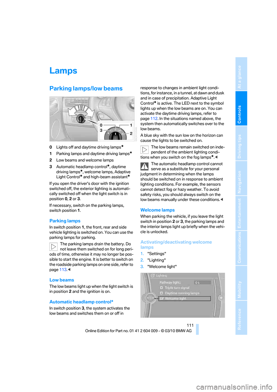
Parking lamps/low beams
0Lights off and daytime driving lamps*
1Parking lamps and daytime driving lamps*
2Low beams and welcome lamps
3Automatic headlamp control
*, daytime
driving lamps
*, welcome lamps, Adaptive
Light Control
* and high-beam assistant*
If you open the driver's door with the ignition
switched off, the exterior lighting is automati-
cally switched off when the light switch is in
position0, 2 or 3.
If necessary, switch on the parking lamps,
switch position1.
Parking lamps
In switch position1, the front, rear and side
vehicle lighting is switched on. You can use the
parking lamps for parking.
The parking lamps drain the battery. Do
not leave them switched on for long peri-
ods of time, otherwise it may no longer be pos-
sible to start the engine. It is better to switch on
the roadside parking lamps on one side, refer to
page113.<
Low beams
The low beams light up when the light switch is
in position 2 and the ignition is on.
Automatic headlamp control*
In switch position3, the system activates the
low beams and switches them on or off in response to changes in ambient light condi-
tions, for instance, in a tunnel, at dawn and dusk
and in case of precipitation. Adaptive Light
Control
* is active. The LED next to the symbol
lights up when the low beams are on. You can
activate the daytime driving lamps, refer to
page112. In the situations named above, the
system then automatically switches over to the
low beams.
A blue sky with the sun low on the horizon can
cause the lights to be switched on.
The low beams remain switched on inde-
pendent of the ambient lighting condi-
tions when you switch on the fog lamps
*.<
The automatic headlamp control cannot
serve as a substitute for your personal
judgment in determining when the lamps
should be switched on in response to ambient
lighting conditions. For example, the sensors
cannot detect fog or hazy weather. To avoid
safety risks, you should always switch on the
low beams manually under these conditions.<
Welcome lamps
When parking the vehicle, if you leave the light
switch in position2 or3, the parking lamps and
the interior lamps light up briefly when the vehi-
cle is unlocked.
Activating/deactivating welcome
lamps
1."Settings"
2."Lighting"
3."Welcome light"
Page 115 of 312
Controls
113Reference
At a glance
Driving tips
Communications
Navigation
Entertainment
Mobility
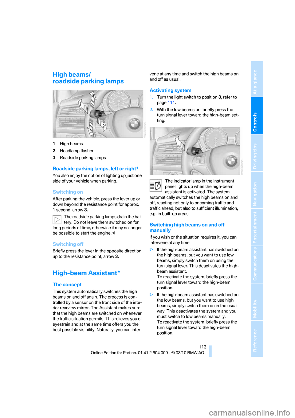
High beams/
roadside parking lamps
1High beams
2Headlamp flasher
3Roadside parking lamps
Roadside parking lamps, left or right*
You also enjoy the option of lighting up just one
side of your vehicle when parking.
Switching on
After parking the vehicle, press the lever up or
down beyond the resistance point for approx.
1 second, arrow3.
The roadside parking lamps drain the bat-
tery. Do not leave them switched on for
long periods of time, otherwise it may no longer
be possible to start the engine.<
Switching off
Briefly press the lever in the opposite direction
up to the resistance point, arrow 3.
High-beam Assistant*
The concept
This system automatically switches the high
beams on and off again. The process is con-
trolled by a sensor on the front side of the inte-
rior rearview mirror. The Assistant makes sure
that the high beams are switched on whenever
the traffic situation permits. This relieves you of
eyestrain and at the same time offers you the
best possible visibility. Naturally, you can inter-vene at any time and switch the high beams on
and off as usual.
Activating system
1.Turn the light switch to position3, refer to
page111.
2.With the low beams on, briefly press the
turn signal lever toward the high-beam set-
ting.
The indicator lamp in the instrument
panel lights up when the high-beam
assistant is activated. The system
automatically switches the high beams on and
off, reacting not only to oncoming traffic and
traffic ahead, but also to sufficient illumination,
e.g. in built-up areas.
Switching high beams on and off
manually
If you wish or the situation requires it, you can
intervene at any time:
>If the high-beam assistant has switched on
the high beams, but you want to use low
beams, simply switch them on using the
turn signal lever. This deactivates the high-
beam assistant.
To reactivate the system, briefly press the
turn signal lever toward the high-beam
position.
>If the high-beam assistant has switched on
the low beams, but you want to use high
beams, simply switch them on in the usual
way. This deactivates the system and you
must switch to low beams manually.
To reactivate the system, briefly press the
turn signal lever toward the high-beam
position.