automatic BMW X5 2013 E70 Workshop Manual
[x] Cancel search | Manufacturer: BMW, Model Year: 2013, Model line: X5, Model: BMW X5 2013 E70Pages: 345, PDF Size: 9.45 MB
Page 118 of 345
system activated, resting your foot on the acel‐
erator pedal will cause the system not to brake
even if necessary. Be certain that floormats or
other objects on the vehicle floor do not inter‐
fere with movement of the acccelerator
pedal.◀
Limits of automatic braking
While active cruise control is capable of
braking your vehicle automatically when you
approach a slower vehicle ahead, it is impor‐
tant to be aware that the ability of the system
to apply the brakes is also limited, e.g. when
you reduce your desired speed sharply. lt uses
only a portion of braking system capacity and
does not utilize the full capacity of the vehicle
braking system. Therefore, the system cannot
decrease your speed for large differences in
speed between your vehicle and the vehicle
ahead. Examples: when you approach a vehicle
traveling at a much lower speed than your own
speed such as approaching a toll booth or
when a much slower vehicle cuts in front of
you at close range.◀
Cruise controlThe concept The system is functional at speeds beginning
at approx. 20 mph/30 km/h.
The speed specified using the lever on the
steering column is maintained.
The system brakes on downhill gradients if en‐
gine braking action is insufficient.
Do not use cruise control
Do not use the system if unfavorable
conditions make it impossible to drive at a con‐
stant speed, for instance:▷On curvy roads.▷In heavy traffic.▷On slippery roads, in fog, snow or rain, or
on a loose road surface.Otherwise, you could lose control of the vehi‐
cle and cause an accident.◀
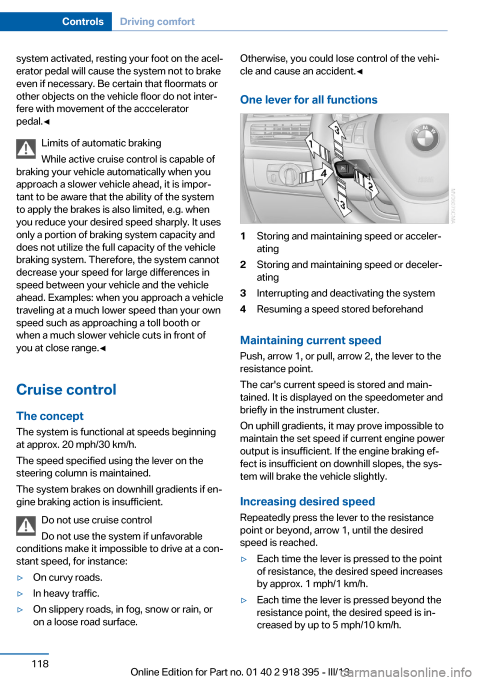
One lever for all functions1Storing and maintaining speed or acceler‐
ating2Storing and maintaining speed or deceler‐
ating3Interrupting and deactivating the system4Resuming a speed stored beforehand
Maintaining current speed
Push, arrow 1, or pull, arrow 2, the lever to the
resistance point.
The car's current speed is stored and main‐ tained. It is displayed on the speedometer and
briefly in the instrument cluster.
On uphill gradients, it may prove impossible to
maintain the set speed if current engine power
output is insufficient. If the engine braking ef‐
fect is insufficient on downhill slopes, the sys‐
tem will brake the vehicle slightly.
Increasing desired speed
Repeatedly press the lever to the resistance
point or beyond, arrow 1, until the desired
speed is reached.
▷Each time the lever is pressed to the point
of resistance, the desired speed increases
by approx. 1 mph/1 km/h.▷Each time the lever is pressed beyond the
resistance point, the desired speed is in‐
creased by up to 5 mph/10 km/h.Seite 118ControlsDriving comfort118
Online Edition for Part no. 01 40 2 918 395 - III/13
Page 120 of 345
Park Distance Control PDCThe concept
In addition to the PDC Park Distance Control,
the backup camera, refer to page 122, can be
switched on.
PDC supports you when parking. A slow ap‐
proach to an object in front of or behind your
vehicle is announced by:▷Signal tones.▷Visual display.
Measurement
Measurements are made by ultrasound sen‐
sors in the bumpers.
The range is approx. 6 ft/2 m.
An acoustic warning is first given:
▷By the front sensors and two rear corner
sensors at approx. 24 in/60 cm.▷By the rear middle sensors at approx.
5 ft/1.50 m.
System limits
Check the traffic situation as well
PDC cannot serve as a substitute for the
driver's personal judgment of the traffic situa‐
tion. Check the traffic situation around the ve‐
hicle with your own eyes. Otherwise, an acci‐
dent could result from road users or objects
located outside of the PDC detection range.
Loud noises from outside and inside the vehi‐
cle may prevent you from hearing the PDC's
signal tone.◀
Avoid driving quickly with PDC
Avoid approaching an object quickly.
Avoid driving away quickly while PDC is not yet
active.
For technical reasons, the system may other‐
wise be too late in issuing a warning.◀
Limits of ultrasonic measurement
The detection of objects can reach the physi‐
cal limits of ultrasonic measurement, for in‐
stance:▷With tow bars and trailer hitches.▷With thin or wedge-shaped objects.▷With low objects.▷With objects with corners and sharp edges.
Low objects already displayed, e.g., curbs, can
move into the blind area of the sensors before
or after a continuous tone sounds.
High, protruding objects such as ledges may
not be detected.
False warnings
PDC may issue a warning under the following
conditions even though there is no obstacle
within the detection range:
▷In heavy rain.▷When sensors are very dirty or covered in
ice.▷When sensors are covered in snow.▷On rough road surfaces.▷In large buildings with right angles and
smooth walls, e.g., in underground ga‐
rages.▷In heavy exhaust.▷Due to other ultrasound sources, e.g.,
sweeping machines, high pressure steam
cleaners or neon lights.
Switching on automatically
With the engine running or the ignition
switched on, shift the selector lever into posi‐
tion R.
Switching off automatically when
driving forward
The system switches off when a certain dis‐
tance or speed is exceeded.
Switch on the system again if necessary.
Seite 120ControlsDriving comfort120
Online Edition for Part no. 01 40 2 918 395 - III/13
Page 122 of 345
Malfunction
A Check Control message, refer to page 85, is
displayed in the instrument cluster.
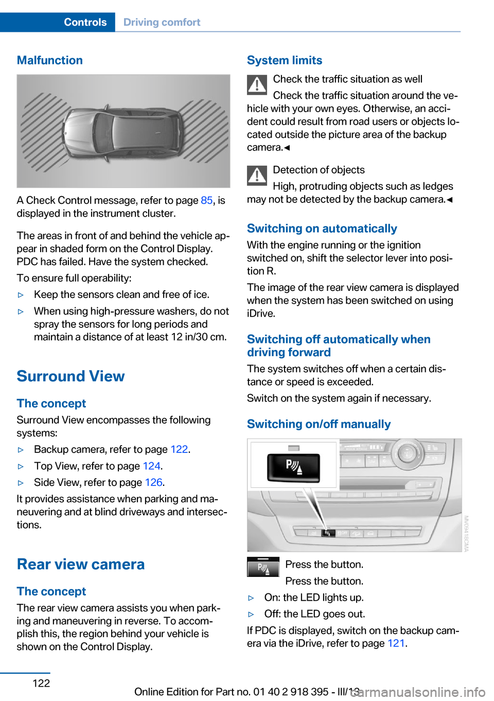
The areas in front of and behind the vehicle ap‐
pear in shaded form on the Control Display.
PDC has failed. Have the system checked.
To ensure full operability:
▷Keep the sensors clean and free of ice.▷When using high-pressure washers, do not
spray the sensors for long periods and
maintain a distance of at least 12 in/30 cm.
Surround View
The concept Surround View encompasses the following
systems:
▷Backup camera, refer to page 122.▷Top View, refer to page 124.▷Side View, refer to page 126.
It provides assistance when parking and ma‐
neuvering and at blind driveways and intersec‐
tions.
Rear view camera
The concept The rear view camera assists you when park‐
ing and maneuvering in reverse. To accom‐
plish this, the region behind your vehicle is
shown on the Control Display.
System limits
Check the traffic situation as well
Check the traffic situation around the ve‐
hicle with your own eyes. Otherwise, an acci‐
dent could result from road users or objects lo‐
cated outside the picture area of the backup
camera.◀
Detection of objects
High, protruding objects such as ledges
may not be detected by the backup camera.◀
Switching on automatically With the engine running or the ignition
switched on, shift the selector lever into posi‐
tion R.
The image of the rear view camera is displayed
when the system has been switched on using
iDrive.
Switching off automatically when
driving forward
The system switches off when a certain dis‐
tance or speed is exceeded.
Switch on the system again if necessary.
Switching on/off manually
Press the button.
Press the button.
▷On: the LED lights up.▷Off: the LED goes out.
If PDC is displayed, switch on the backup cam‐
era via the iDrive, refer to page 121.
Seite 122ControlsDriving comfort122
Online Edition for Part no. 01 40 2 918 395 - III/13
Page 125 of 345
▷Approx. 7 ft/2 m to the side.▷Approx. 7 ft/2 m to the rear.
Obstacles up to the height of the exterior mir‐
rors are thus detected in a timely fashion.
System limits
Top View cannot be used in the following sit‐
uations:
▷With a door open.▷With the tailgate open.▷With an exterior mirror folded in.▷In poor light.
The arrows next to the vehicle are displayed in
a shaded form on the Control Display and a
symbol appears at the corresponding location
on the vehicle.
Check the traffic situation as well
Check the traffic situation around the ve‐
hicle with your own eyes. Otherwise, an acci‐
dent could result from road users or objects lo‐
cated outside the picture area of the
cameras.◀
Switching on automatically
Select transmission position R with the engine
running.
The images from Top View and PDC are dis‐
played when the system has been switched on
using iDrive.
Switching off automatically when
driving forward
The system switches off when a certain dis‐
tance or speed is exceeded.
Switch on the system again if necessary.
Switching on/off manually
Press the button.
▷On: the LED lights up.▷Off: the LED goes out.
If Top View is displayed, switch on the backup
camera via the iDrive, refer to page 124.
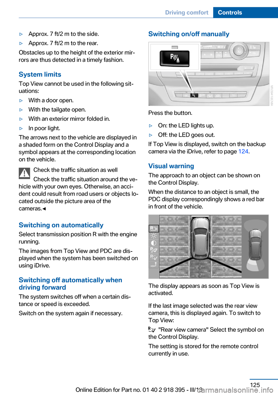
Visual warning
The approach to an object can be shown on
the Control Display.
When the distance to an object is small, the
PDC display correspondingly shows a red bar
in front of the vehicle.
The display appears as soon as Top View is
activated.
If the last image selected was the rear view
camera, this is displayed again. To switch to
Top View:
"Rear view camera" Select the symbol on
the Control Display.
The setting is stored for the remote control
currently in use.
Seite 125Driving comfortControls125
Online Edition for Part no. 01 40 2 918 395 - III/13
Page 127 of 345
Switching off automatically when
driving forward
The system switches off when a certain dis‐
tance or speed is exceeded.
Switch on the system again if necessary.
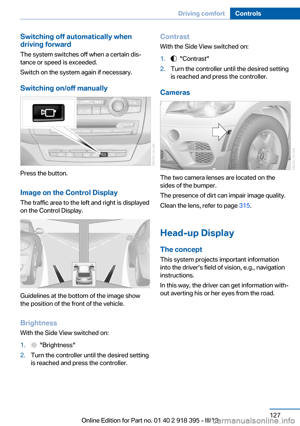
Switching on/off manually
Press the button.
Image on the Control Display
The traffic area to the left and right is displayed
on the Control Display.
Guidelines at the bottom of the image show
the position of the front of the vehicle.
Brightness With the Side View switched on:
1. "Brightness"2.Turn the controller until the desired setting
is reached and press the controller.Contrast
With the Side View switched on:1. "Contrast"2.Turn the controller until the desired setting
is reached and press the controller.
Cameras
The two camera lenses are located on the
sides of the bumper.
The presence of dirt can impair image quality.
Clean the lens, refer to page 315.
Head-up Display
The concept This system projects important information
into the driver's field of vision, e.g., navigation
instructions.
In this way, the driver can get information with‐
out averting his or her eyes from the road.
Seite 127Driving comfortControls127
Online Edition for Part no. 01 40 2 918 395 - III/13
Page 128 of 345
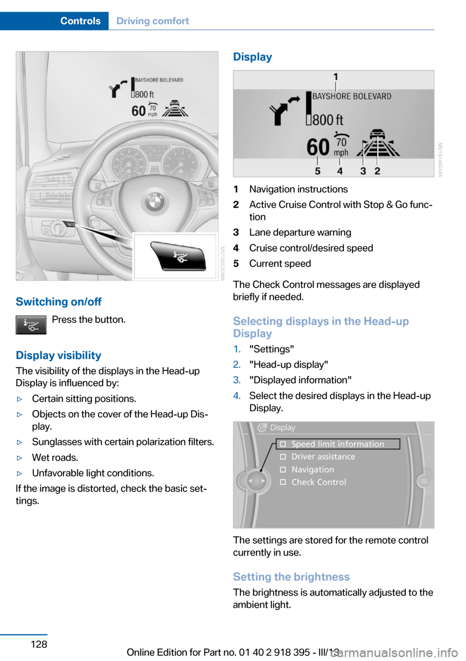
Switching on/offPress the button.
Display visibility The visibility of the displays in the Head-up
Display is influenced by:
▷Certain sitting positions.▷Objects on the cover of the Head-up Dis‐
play.▷Sunglasses with certain polarization filters.▷Wet roads.▷Unfavorable light conditions.
If the image is distorted, check the basic set‐
tings.
Display1Navigation instructions2Active Cruise Control with Stop & Go func‐
tion3Lane departure warning4Cruise control/desired speed5Current speed
The Check Control messages are displayed
briefly if needed.
Selecting displays in the Head-up
Display
1."Settings"2."Head-up display"3."Displayed information"4.Select the desired displays in the Head-up
Display.
The settings are stored for the remote control
currently in use.
Setting the brightness
The brightness is automatically adjusted to the
ambient light.
Seite 128ControlsDriving comfort128
Online Edition for Part no. 01 40 2 918 395 - III/13
Page 130 of 345
ClimateVehicle equipmentThis chapter describes all series equipment as
well as country-specific and special equipment
offered for this model series.Therefore, it alsodescribes equipment that may not be found in
your vehicle, for instance due to the selected
special equipment or the country version. This
also applies to safety-related functions and
systems.
At a glance
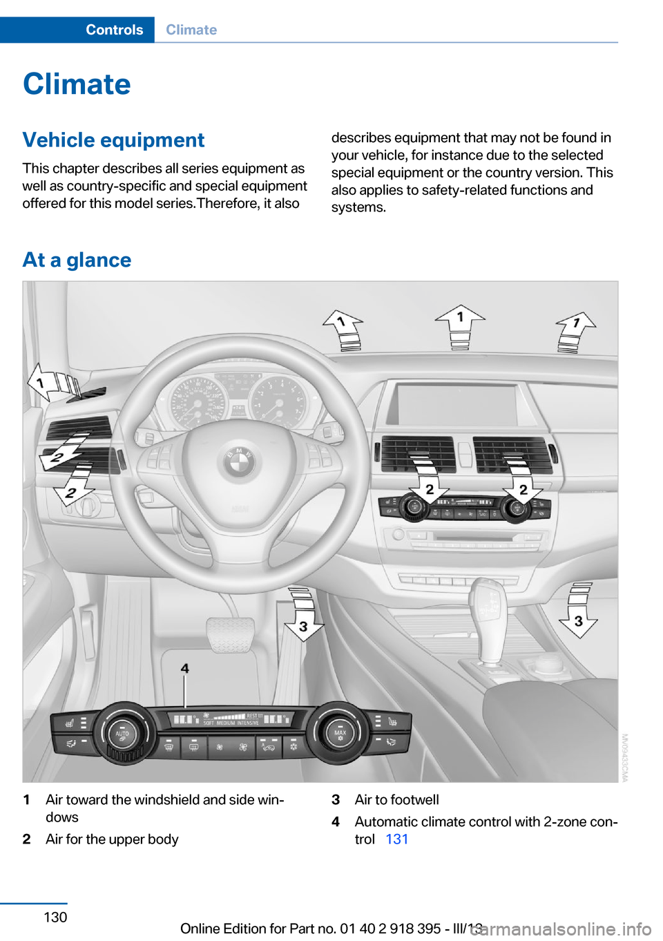
1Air toward the windshield and side win‐
dows2Air for the upper body3Air to footwell4Automatic climate control with 2-zone con‐
trol 131Seite 130ControlsClimate130
Online Edition for Part no. 01 40 2 918 395 - III/13
Page 131 of 345
Automatic climate control with 4-zone con‐
trol 135
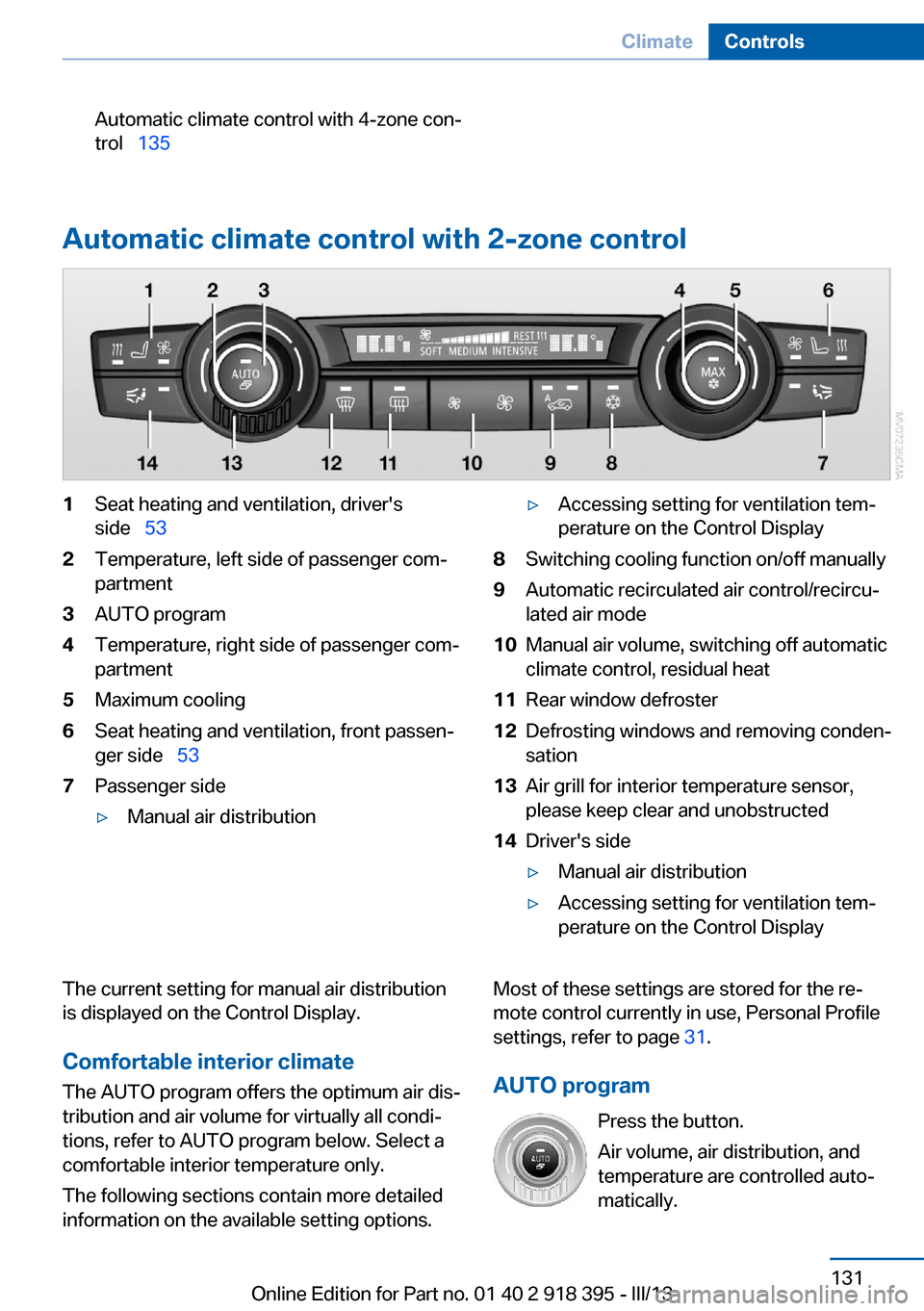
Automatic climate control with 2-zone control
1Seat heating and ventilation, driver's
side 532Temperature, left side of passenger com‐
partment3AUTO program4Temperature, right side of passenger com‐
partment5Maximum cooling6Seat heating and ventilation, front passen‐
ger side 537Passenger side▷Manual air distribution▷Accessing setting for ventilation tem‐
perature on the Control Display8Switching cooling function on/off manually9Automatic recirculated air control/recircu‐
lated air mode10Manual air volume, switching off automatic
climate control, residual heat11Rear window defroster12Defrosting windows and removing conden‐
sation13Air grill for interior temperature sensor,
please keep clear and unobstructed14Driver's side▷Manual air distribution▷Accessing setting for ventilation tem‐
perature on the Control DisplayThe current setting for manual air distribution
is displayed on the Control Display.
Comfortable interior climate The AUTO program offers the optimum air dis‐
tribution and air volume for virtually all condi‐
tions, refer to AUTO program below. Select a
comfortable interior temperature only.
The following sections contain more detailed
information on the available setting options.Most of these settings are stored for the re‐
mote control currently in use, Personal Profile
settings, refer to page 31.
AUTO program Press the button.
Air volume, air distribution, and
temperature are controlled auto‐
matically.Seite 131ClimateControls131
Online Edition for Part no. 01 40 2 918 395 - III/13
Page 132 of 345
Depending on the selected temperature,
AUTO intensity, and outside influences, the air
is directed to the windshield, side windows,
upper body, and into the footwell.
The cooling function is switched on automati‐
cally with the AUTO program.
At the same time, a condensation sensor con‐
trols the program in such a way that window
condensation is prevented as much as possi‐
ble.
To switch off the program: press the button
again or manually adjust the air distribution.
Intensity of the AUTO program
Pressing the AUTO button repeatedly adjusts
the intensity of the AUTO program. The se‐
lected intensity, SOFT, MEDIUM or INTEN‐
SIVE, appears on the display of the automatic
climate control.
Temperature Turn the wheel to set the desired
temperature.
The automatic climate control
achieves this temperature as
quickly as possible, if necessary with the maxi‐
mum cooling or heating capacity, and then
keeps it constant.
Avoid rapidly switching between different tem‐
perature settings. The automatic climate con‐
trol will not have sufficient time to adjust the set temperature.
Maximum heating power can be obtained with
the highest setting, regardless of the external
temperature.
At the lowest setting, cooling is continuous, re‐
gardless of the external temperature.Adjusting the ventilation temperature
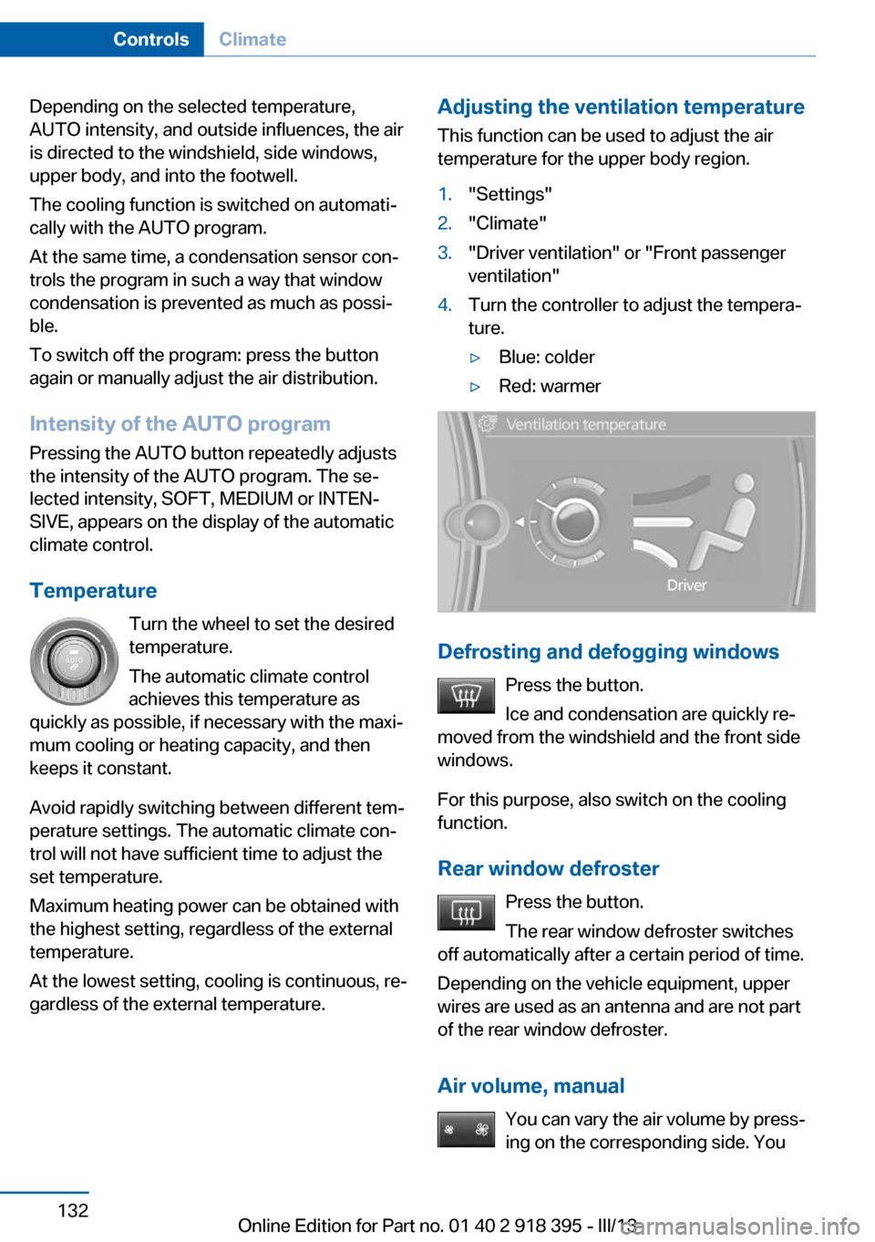
This function can be used to adjust the air
temperature for the upper body region.1."Settings"2."Climate"3."Driver ventilation" or "Front passenger
ventilation"4.Turn the controller to adjust the tempera‐
ture.▷Blue: colder▷Red: warmer
Defrosting and defogging windows
Press the button.
Ice and condensation are quickly re‐
moved from the windshield and the front side
windows.
For this purpose, also switch on the cooling
function.
Rear window defroster Press the button.
The rear window defroster switches
off automatically after a certain period of time.
Depending on the vehicle equipment, upper
wires are used as an antenna and are not part
of the rear window defroster.
Air volume, manual You can vary the air volume by press‐
ing on the corresponding side. You
Seite 132ControlsClimate132
Online Edition for Part no. 01 40 2 918 395 - III/13
Page 133 of 345
can reactivate the automatic mode for the air
volume with the AUTO button.
Manual air distribution
The air flow can be guided into the vehicle in‐
terior, separately for the driver's and front pas‐
senger side, using one of the following pro‐
grams:▷Upper body region.▷Upper body region and footwell.▷Footwell.▷Driver's side: in addition, the windshield,
side windows, and footwell.
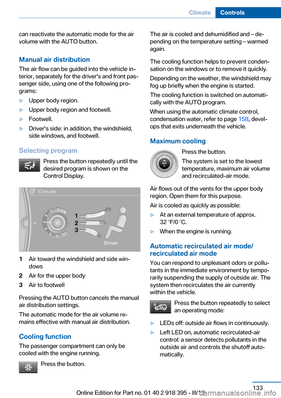
Selecting program
Press the button repeatedly until the
desired program is shown on the
Control Display.
1Air toward the windshield and side win‐
dows2Air for the upper body3Air to footwell
Pressing the AUTO button cancels the manual
air distribution settings.
The automatic mode for the air volume re‐
mains effective with manual air distribution.
Cooling function
The passenger compartment can only be
cooled with the engine running.
Press the button.
The air is cooled and dehumidified and – de‐
pending on the temperature setting – warmed
again.
The cooling function helps to prevent conden‐
sation on the windows or to remove it quickly.
Depending on the weather, the windshield may
fog up briefly when the engine is started.
The cooling function is switched on automati‐
cally with the AUTO program.
When using the automatic climate control,
condensation water, refer to page 158, devel‐
ops that exits underneath the vehicle.
Maximum cooling Press the button.
The system is set to the lowest
temperature, maximum air volume
and recirculated-air mode.
Air flows out of the vents for the upper body
region. Open them for this purpose.
Air is cooled as quickly as possible:▷At an external temperature of approx.
32 ℉/0 ℃.▷When the engine is running.
Automatic recirculated air mode/
recirculated air mode
You can respond to unpleasant odors or pollu‐
tants in the immediate environment by tempo‐
rarily suspending the supply of outside air. The
system then recirculates the air currently
within the vehicle.
Press the button repeatedly to select
an operating mode:
▷LEDs off: outside air flows in continuously.▷Left LED on, automatic recirculated-air
control: a sensor detects pollutants in the
outside air and controls the shutoff auto‐
matically.Seite 133ClimateControls133
Online Edition for Part no. 01 40 2 918 395 - III/13