BMW X5 2014 F15 Owners Manual
Manufacturer: BMW, Model Year: 2014, Model line: X5, Model: BMW X5 2014 F15Pages: 265, PDF Size: 6.2 MB
Page 91 of 265
Automatic Service Request
Data regarding the service status or legally
mandated inspections of the vehicle are auto‐
matically transmitted to your service center
before a service due date.
You can check when your service center was
notified.1."Vehicle Info"2."Vehicle status"3.Open "Options".4."Last Service Request"
Gear shift indicator
The conceptThe system recommends the most fuel effi‐
cient gear for the current driving situation.
Depending on how the vehicle is equipped and
the country-specific version of the vehicle, the
gear shift indicator is active in the manual
mode of the automatic transmission.
Indicators to shift up or down are displayed in
the instrument cluster.
On vehicles without a gear shift indicator, the
engaged gear is displayed.
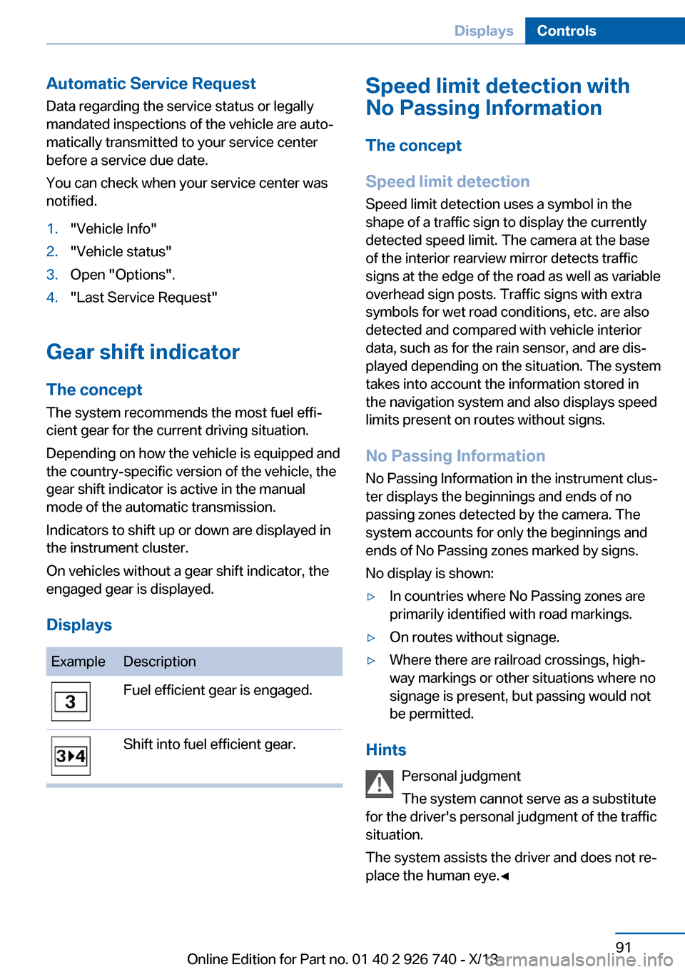
Displays
ExampleDescriptionFuel efficient gear is engaged.Shift into fuel efficient gear.Speed limit detection with
No Passing Information
The concept
Speed limit detection Speed limit detection uses a symbol in the
shape of a traffic sign to display the currently
detected speed limit. The camera at the base
of the interior rearview mirror detects traffic
signs at the edge of the road as well as variable
overhead sign posts. Traffic signs with extra
symbols for wet road conditions, etc. are also
detected and compared with vehicle interior
data, such as for the rain sensor, and are dis‐
played depending on the situation. The system
takes into account the information stored in
the navigation system and also displays speed
limits present on routes without signs.
No Passing Information No Passing Information in the instrument clus‐
ter displays the beginnings and ends of no
passing zones detected by the camera. The
system accounts for only the beginnings and
ends of No Passing zones marked by signs.
No display is shown:▷In countries where No Passing zones are
primarily identified with road markings.▷On routes without signage.▷Where there are railroad crossings, high‐
way markings or other situations where no
signage is present, but passing would not
be permitted.
Hints
Personal judgment
The system cannot serve as a substitute
for the driver's personal judgment of the traffic
situation.
The system assists the driver and does not re‐
place the human eye.◀
Seite 91DisplaysControls91
Online Edition for Part no. 01 40 2 926 740 - X/13
Page 92 of 265
At a glance
Camera
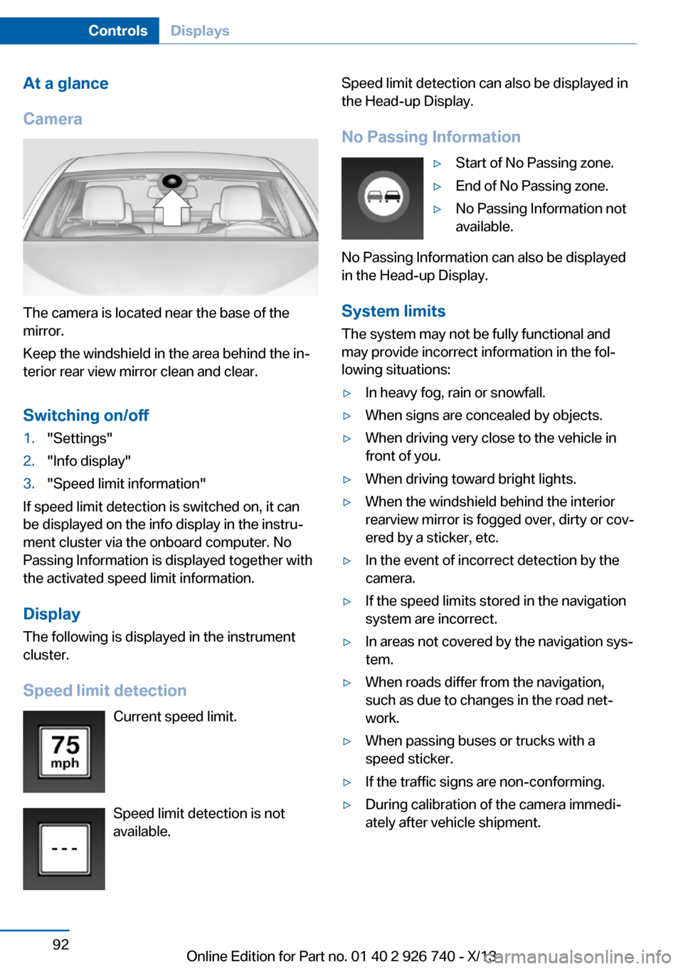
The camera is located near the base of the
mirror.
Keep the windshield in the area behind the in‐
terior rear view mirror clean and clear.
Switching on/off
1."Settings"2."Info display"3."Speed limit information"
If speed limit detection is switched on, it can
be displayed on the info display in the instru‐
ment cluster via the onboard computer. No
Passing Information is displayed together with
the activated speed limit information.
Display The following is displayed in the instrument
cluster.
Speed limit detection Current speed limit.
Speed limit detection is not available.
Speed limit detection can also be displayed in
the Head-up Display.
No Passing Information▷Start of No Passing zone.▷End of No Passing zone.▷No Passing Information not
available.
No Passing Information can also be displayed
in the Head-up Display.
System limits
The system may not be fully functional and
may provide incorrect information in the fol‐ lowing situations:
▷In heavy fog, rain or snowfall.▷When signs are concealed by objects.▷When driving very close to the vehicle in
front of you.▷When driving toward bright lights.▷When the windshield behind the interior
rearview mirror is fogged over, dirty or cov‐
ered by a sticker, etc.▷In the event of incorrect detection by the
camera.▷If the speed limits stored in the navigation
system are incorrect.▷In areas not covered by the navigation sys‐
tem.▷When roads differ from the navigation,
such as due to changes in the road net‐
work.▷When passing buses or trucks with a
speed sticker.▷If the traffic signs are non-conforming.▷During calibration of the camera immedi‐
ately after vehicle shipment.Seite 92ControlsDisplays92
Online Edition for Part no. 01 40 2 926 740 - X/13
Page 93 of 265
Selection lists in the
instrument cluster
The concept
The following can be operated using the but‐
tons and the thumbwheel on the steering
wheel:
▷Current audio source.▷Redial on telephone.▷Activation of the voice activation system.
Activating a list and creating the
setting
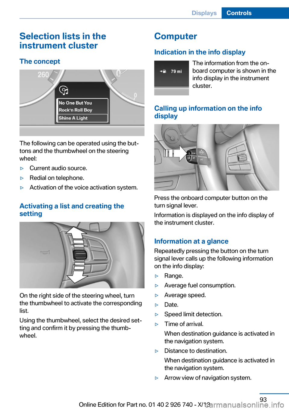
On the right side of the steering wheel, turn
the thumbwheel to activate the corresponding
list.
Using the thumbwheel, select the desired set‐
ting and confirm it by pressing the thumb‐
wheel.
Computer
Indication in the info display The information from the on‐
board computer is shown in the
info display in the instrument
cluster.
Calling up information on the info
display
Press the onboard computer button on the
turn signal lever.
Information is displayed on the info display of
the instrument cluster.
Information at a glance
Repeatedly pressing the button on the turn
signal lever calls up the following information
on the info display:
▷Range.▷Average fuel consumption.▷Average speed.▷Date.▷Speed limit detection.▷Time of arrival.
When destination guidance is activated in
the navigation system.▷Distance to destination.
When destination guidance is activated in
the navigation system.▷Arrow view of navigation system.Seite 93DisplaysControls93
Online Edition for Part no. 01 40 2 926 740 - X/13
Page 94 of 265
When destination guidance is activated in
the navigation system.
When the arrow view in the Head-up Dis‐
play is inactive.▷Compass display in the navigation system.
Adjusting the info display
You can select what information from the on‐
board computer is to be displayed on the info
display of the instrument cluster.
1."Settings"2."Info display"3.Select the desired displays.
Information in detail
Range
Displays the estimated cruising range available
with the remaining fuel.
It is calculated based on your driving style over
the last 20 miles/30 km.
Average fuel consumption
The average fuel consumption is calculated for
the period during which the engine is running.
The average fuel consumption is calculated for
the distance traveled since the last reset by the
onboard computer.
Average speed
Periods in which the vehicle is parked with the
engine manually stopped do not enter into the
calculation of the average speed.
Resetting average values
Press and hold the computer button on the turn signal lever.
Distance to destination
The distance remaining to the destination is
displayed if a destination is entered in the navi‐
gation system before the trip is started.
The distance to the destination is adopted au‐
tomatically.
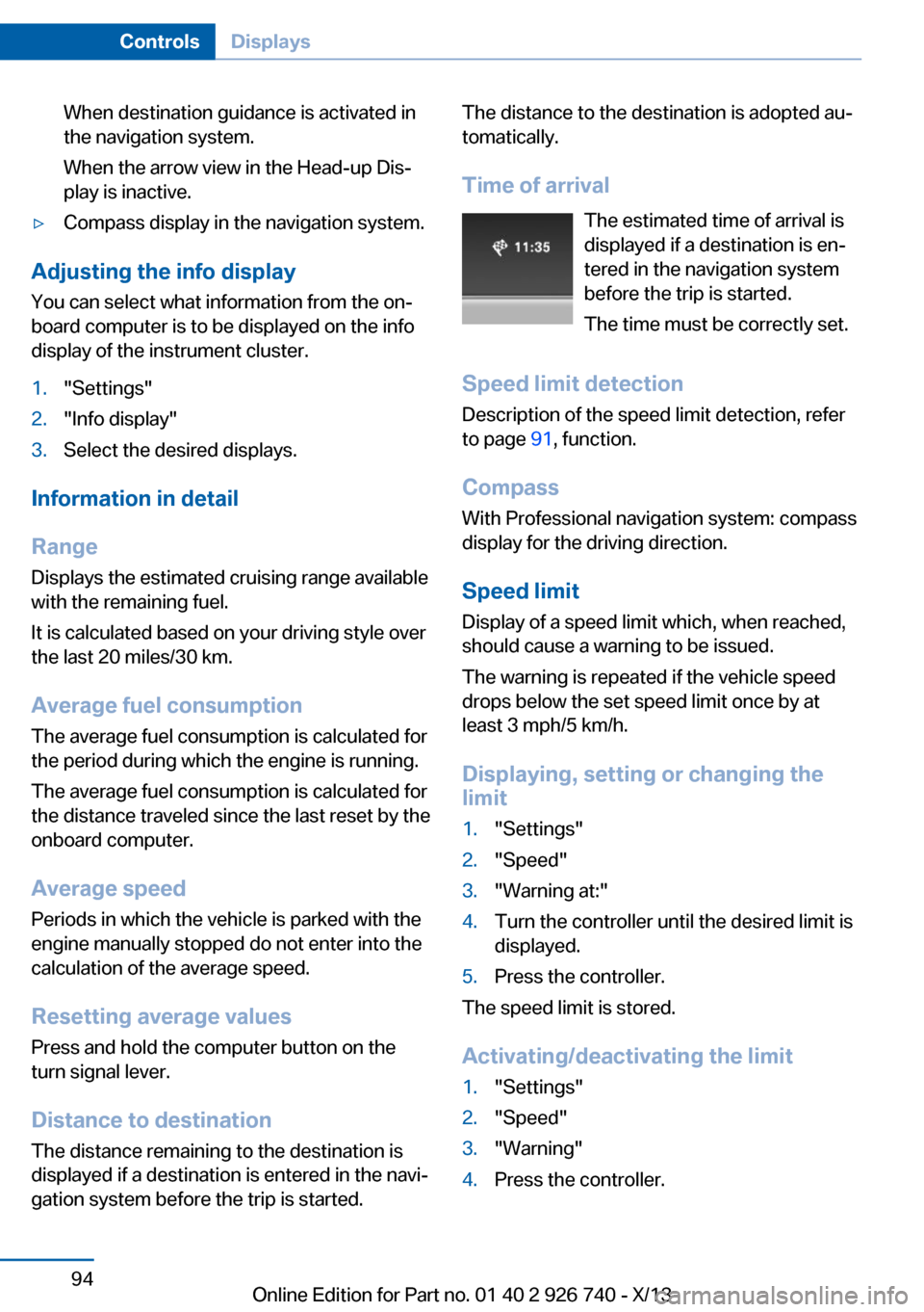
Time of arrival The estimated time of arrival is
displayed if a destination is en‐
tered in the navigation system
before the trip is started.
The time must be correctly set.
Speed limit detection
Description of the speed limit detection, refer
to page 91, function.
Compass With Professional navigation system: compass
display for the driving direction.
Speed limit
Display of a speed limit which, when reached,
should cause a warning to be issued.
The warning is repeated if the vehicle speed
drops below the set speed limit once by at
least 3 mph/5 km/h.
Displaying, setting or changing the
limit1."Settings"2."Speed"3."Warning at:"4.Turn the controller until the desired limit is
displayed.5.Press the controller.
The speed limit is stored.
Activating/deactivating the limit
1."Settings"2."Speed"3."Warning"4.Press the controller.Seite 94ControlsDisplays94
Online Edition for Part no. 01 40 2 926 740 - X/13
Page 95 of 265
Setting your current speed as the limit1."Settings"2."Speed"3."Select current speed"4.Press the controller.
The current vehicle speed is stored as the
limit.
Trip computer
The vehicle features two types of computer.
▷"Onboard info": the values can be reset as
often as necessary.▷"Trip computer": the values provide an
overview of the current trip.
Resetting the trip computer
1."Vehicle Info"2."Trip computer"3."Reset": all values are reset.
"Automatically reset": all values are reset
approx. 4 hours after the vehicle comes to
a standstill.
Display on the Control Display
Display the onboard computer or trip computer
on the Control Display.
1."Vehicle Info"2."Onboard info" or "Trip computer"
Resetting the fuel consumption or
speed
1."Vehicle Info"2."Onboard info"3."Consumpt." or "Speed"4."Yes"Sport displays
In the Control Display, the current values for
power and torque can be displayed if the vehi‐
cle is appropriately equipped.
Displaying sport displays in the
Control Display1."Vehicle Info"2."Sport displays"
Settings on the Control
Display
Time
Setting the time zone
1."Settings"2."Time/Date"3."Time zone"4.Select the desired time zone.
The time zone is stored.
Setting the time
1."Settings"2."Time/Date"3."Time:"4.Turn the controller until the desired hours
are displayed.5.Press the controller.6.Turn the controller until the desired mi‐
nutes are displayed.7.Press the controller.
The time is stored.
Setting the time format
1."Settings"2."Time/Date"3."Format:"4.Select the desired format.Seite 95DisplaysControls95
Online Edition for Part no. 01 40 2 926 740 - X/13
Page 96 of 265
The time format is stored.
Date
Setting the date1."Settings"2."Time/Date"3."Date:"4.Turn the controller until the desired day is
displayed.5.Press the controller.6.Make the necessary settings for the month
and year.
The date is stored.
Setting the date format
1."Settings"2."Time/Date"3."Format:"4.Select the desired format.
The date format is stored.
Language
Setting the language
To set the language on the Control Display:
1."Settings"2."Language/Units"3."Language:"4.Select the desired language.
The setting is stored for the remote control
currently in use.
Setting the voice dialog
Voice dialog for the voice activation system,
refer to page 27.
Units of measure
Setting the units of measure
To set the units for fuel consumption, route/
distance and temperature:1."Settings"2."Language/Units"3.Select the desired menu item.4.Select the desired unit.
The setting is stored for the remote control
currently in use.
Brightness
Setting the brightness
To set the brightness of the Control Display:
1."Settings"2."Control display"3."Brightness"4.Turn the controller until the desired bright‐
ness is set.5.Press the controller.
The setting is stored for the remote control
currently in use.
Depending on the light conditions, the bright‐
ness control may not be clearly visible.
Seite 96ControlsDisplays96
Online Edition for Part no. 01 40 2 926 740 - X/13
Page 97 of 265
Head-up Display
The concept
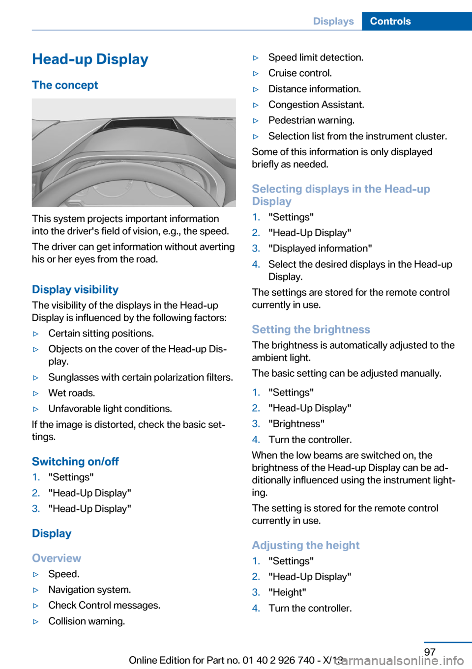
This system projects important information
into the driver's field of vision, e.g., the speed.
The driver can get information without averting
his or her eyes from the road.
Display visibility The visibility of the displays in the Head-up
Display is influenced by the following factors:
▷Certain sitting positions.▷Objects on the cover of the Head-up Dis‐
play.▷Sunglasses with certain polarization filters.▷Wet roads.▷Unfavorable light conditions.
If the image is distorted, check the basic set‐
tings.
Switching on/off
1."Settings"2."Head-Up Display"3."Head-Up Display"
Display
Overview
▷Speed.▷Navigation system.▷Check Control messages.▷Collision warning.▷Speed limit detection.▷Cruise control.▷Distance information.▷Congestion Assistant.▷Pedestrian warning.▷Selection list from the instrument cluster.
Some of this information is only displayed
briefly as needed.
Selecting displays in the Head-up
Display
1."Settings"2."Head-Up Display"3."Displayed information"4.Select the desired displays in the Head-up
Display.
The settings are stored for the remote control
currently in use.
Setting the brightness
The brightness is automatically adjusted to the
ambient light.
The basic setting can be adjusted manually.
1."Settings"2."Head-Up Display"3."Brightness"4.Turn the controller.
When the low beams are switched on, the
brightness of the Head-up Display can be ad‐
ditionally influenced using the instrument light‐
ing.
The setting is stored for the remote control
currently in use.
Adjusting the height
1."Settings"2."Head-Up Display"3."Height"4.Turn the controller.Seite 97DisplaysControls97
Online Edition for Part no. 01 40 2 926 740 - X/13
Page 98 of 265
The setting is stored for the remote control
currently in use.
Setting the rotation1."Settings"2."Head-Up Display"3."Rotation"4.Turn the controller.
The setting is stored for the remote control
currently in use.
Special windshield
The windshield is part of the system.
The shape of the windshield makes it possible
to display a precise image.
A film in the windshield prevents double im‐
ages from being displayed.
Therefore, have the special windshield re‐
placed by a service center only.
Seite 98ControlsDisplays98
Online Edition for Part no. 01 40 2 926 740 - X/13
Page 99 of 265
LampsVehicle equipment
All standard, country-specific and optional
equipment that is offered in the model series is
described in this chapter. Therefore, equip‐
ment is also described that is not available in a
vehicle, e. g., because of the selected optional
equipment or country variant. This also applies
for safety-related functions and systems.
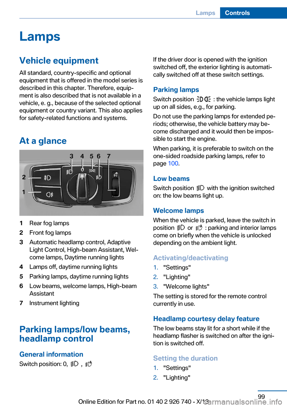
At a glance1Rear fog lamps2Front fog lamps3Automatic headlamp control, Adaptive
Light Control, High-beam Assistant, Wel‐
come lamps, Daytime running lights4Lamps off, daytime running lights5Parking lamps, daytime running lights6Low beams, welcome lamps, High-beam
Assistant7Instrument lighting
Parking lamps/low beams,
headlamp control
General information Switch position: 0,
,
If the driver door is opened with the ignition
switched off, the exterior lighting is automati‐
cally switched off at these switch settings.
Parking lamps
Switch position
: the vehicle lamps light
up on all sides, e.g., for parking.
Do not use the parking lamps for extended pe‐
riods; otherwise, the vehicle battery may be‐
come discharged and it would then be impos‐
sible to start the engine.
When parking, it is preferable to switch on the
one-sided roadside parking lamps, refer to
page 100.
Low beams Switch position
with the ignition switched
on: the low beams light up.
Welcome lamps When the vehicle is parked, leave the switch in
position
or : parking and interior lamps
come on briefly when the vehicle is unlocked
depending on the ambient light.
Activating/deactivating
1."Settings"2."Lighting"3."Welcome lights"
The setting is stored for the remote control
currently in use.
Headlamp courtesy delay feature
The low beams stay lit for a short while if the
headlamp flasher is switched on after the igni‐
tion is switched off.
Setting the duration
1."Settings"2."Lighting"Seite 99LampsControls99
Online Edition for Part no. 01 40 2 926 740 - X/13
Page 100 of 265
3."Pathway lighting:"4.Set the duration.
The setting is stored for the remote control
currently in use.
Automatic headlamp control
Switch position
: the low beams are
switched on and off automatically, e.g., in tun‐
nels, in twilight or if there is precipitation. The
indicator lamp in the instrument cluster lights
up.
A blue sky with the sun low on the horizon can
cause the lights to be switched on.
The low beams always stay on when the fog
lamps are switched on.
Personal responsibility
The automatic headlamp control cannot
serve as a substitute for your personal judg‐
ment in determining when the lamps should be
switched on in response to ambient lighting
conditions.
For example, the sensors are unable to detect
fog or hazy weather. To avoid safety risks, you
should always switch on the lamps manually
under these conditions.◀
Daytime running lights With the ignition switched on, the daytime run‐
ning lights light up in position 0,
or .
After the ignition is switched off, the parking
lamps light up in position
.
Activating/deactivating
In some countries, daytime running lights are
compulsory, so it may not be possible to deac‐
tivate the daytime running lights.
1."Settings"2."Lighting"3."Daytime running lamps"
The setting is stored for the remote control
currently in use.
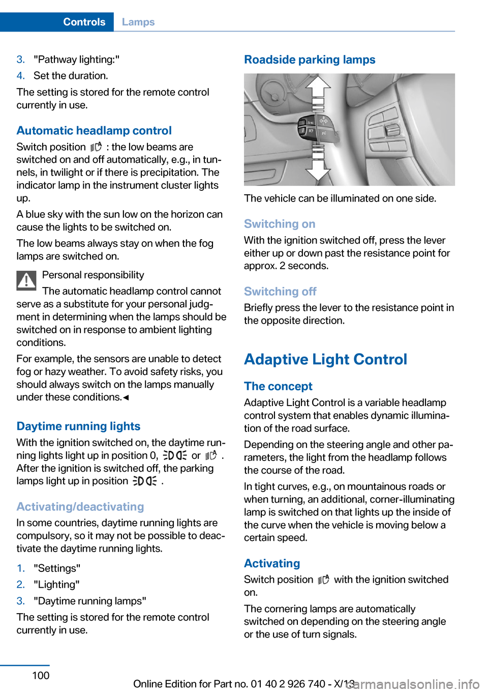
Roadside parking lamps
The vehicle can be illuminated on one side.
Switching on With the ignition switched off, press the lever
either up or down past the resistance point for
approx. 2 seconds.
Switching off Briefly press the lever to the resistance point in
the opposite direction.
Adaptive Light Control The conceptAdaptive Light Control is a variable headlamp
control system that enables dynamic illumina‐
tion of the road surface.
Depending on the steering angle and other pa‐
rameters, the light from the headlamp follows
the course of the road.
In tight curves, e.g., on mountainous roads or
when turning, an additional, corner-illuminating
lamp is switched on that lights up the inside of
the curve when the vehicle is moving below a
certain speed.
Activating Switch position
with the ignition switched
on.
The cornering lamps are automatically
switched on depending on the steering angle
or the use of turn signals.
Seite 100ControlsLamps100
Online Edition for Part no. 01 40 2 926 740 - X/13