ACC BMW X5 2014 F15 Owner's Guide
[x] Cancel search | Manufacturer: BMW, Model Year: 2014, Model line: X5, Model: BMW X5 2014 F15Pages: 265, PDF Size: 6.2 MB
Page 77 of 265
Rear window wiper
Switching on the rear window wiper
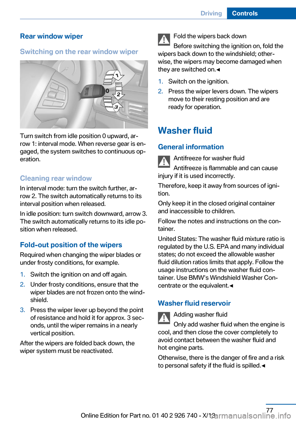
Turn switch from idle position 0 upward, ar‐
row 1: interval mode. When reverse gear is en‐
gaged, the system switches to continuous op‐
eration.
Cleaning rear window
In interval mode: turn the switch further, ar‐
row 2. The switch automatically returns to its
interval position when released.
In idle position: turn switch downward, arrow 3.
The switch automatically returns to its idle po‐
sition when released.
Fold-out position of the wipers Required when changing the wiper blades or
under frosty conditions, for example.
1.Switch the ignition on and off again.2.Under frosty conditions, ensure that the
wiper blades are not frozen onto the wind‐
shield.3.Press the wiper lever up beyond the point
of resistance and hold it for approx. 3 sec‐
onds, until the wiper remains in a nearly
vertical position.
After the wipers are folded back down, the
wiper system must be reactivated.
Fold the wipers back down
Before switching the ignition on, fold the
wipers back down to the windshield; other‐
wise, the wipers may become damaged when
they are switched on.◀1.Switch on the ignition.2.Press the wiper levers down. The wipers
move to their resting position and are
ready for operation.
Washer fluid
General information Antifreeze for washer fluid
Antifreeze is flammable and can cause
injury if it is used incorrectly.
Therefore, keep it away from sources of igni‐
tion.
Only keep it in the closed original container
and inaccessible to children.
Follow the notes and instructions on the con‐
tainer.
United States: The washer fluid mixture ratio is
regulated by the U.S. EPA and many individual
states; do not exceed the allowable washer
fluid dilution ratios limits that apply. Follow the
usage instructions on the washer fluid con‐
tainer. Use BMW’s Windshield Washer Con‐
centrate or the equivalent.◀
Washer fluid reservoir Adding washer fluid
Only add washer fluid when the engine is
cool, and then close the cover completely to
avoid contact between the washer fluid and
hot engine parts.
Otherwise, there is the danger of fire and a risk
to personal safety if the fluid is spilled.◀
Seite 77DrivingControls77
Online Edition for Part no. 01 40 2 926 740 - X/13
Page 78 of 265
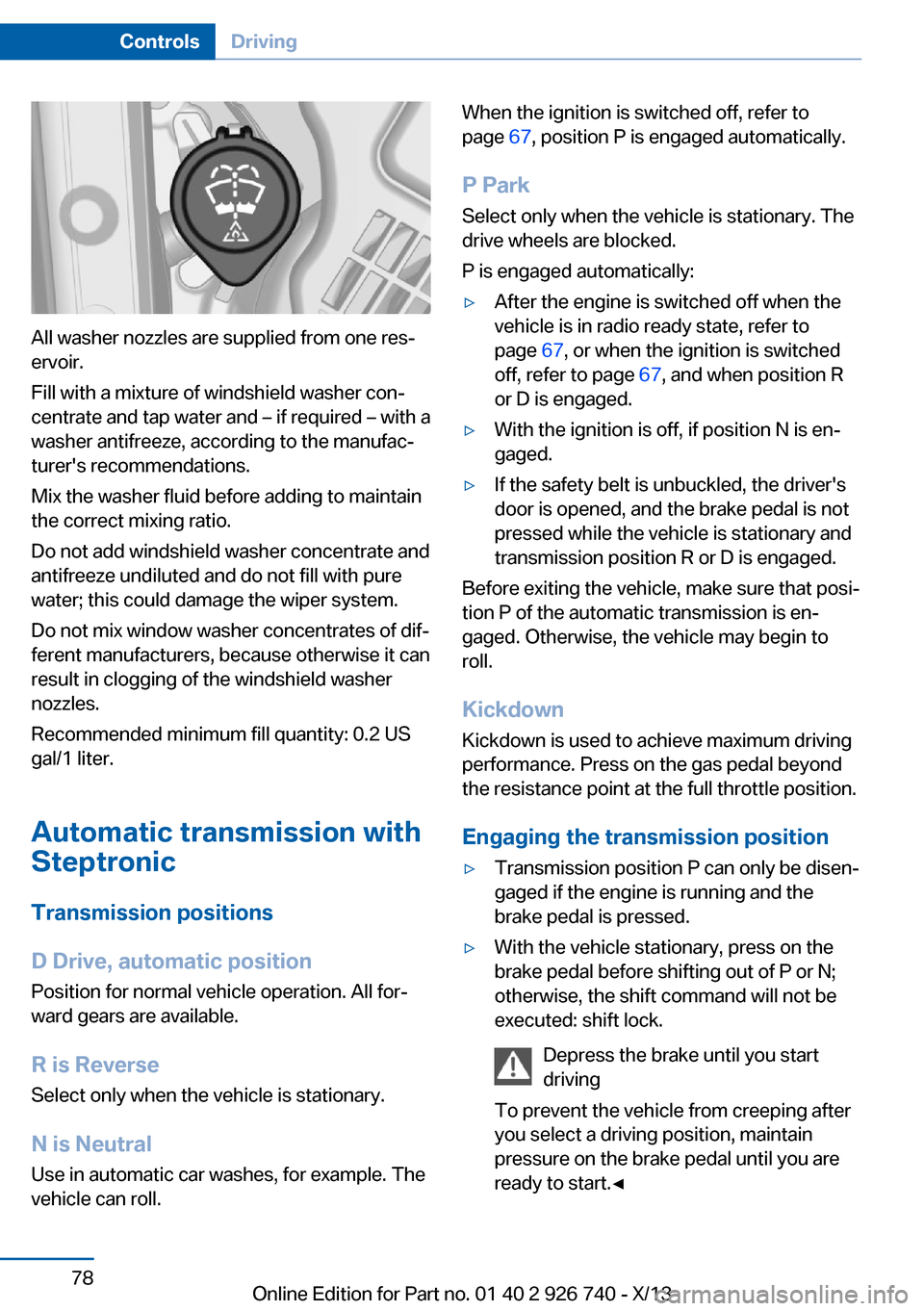
All washer nozzles are supplied from one res‐
ervoir.
Fill with a mixture of windshield washer con‐
centrate and tap water and – if required – with a
washer antifreeze, according to the manufac‐
turer's recommendations.
Mix the washer fluid before adding to maintain
the correct mixing ratio.
Do not add windshield washer concentrate and
antifreeze undiluted and do not fill with pure
water; this could damage the wiper system.
Do not mix window washer concentrates of dif‐
ferent manufacturers, because otherwise it can
result in clogging of the windshield washer
nozzles.
Recommended minimum fill quantity: 0.2 US
gal/1 liter.
Automatic transmission with
Steptronic
Transmission positions
D Drive, automatic position Position for normal vehicle operation. All for‐
ward gears are available.
R is Reverse
Select only when the vehicle is stationary.
N is Neutral Use in automatic car washes, for example. The
vehicle can roll.
When the ignition is switched off, refer to
page 67, position P is engaged automatically.
P Park
Select only when the vehicle is stationary. The
drive wheels are blocked.
P is engaged automatically:▷After the engine is switched off when the
vehicle is in radio ready state, refer to
page 67, or when the ignition is switched
off, refer to page 67, and when position R
or D is engaged.▷With the ignition is off, if position N is en‐
gaged.▷If the safety belt is unbuckled, the driver's
door is opened, and the brake pedal is not
pressed while the vehicle is stationary and
transmission position R or D is engaged.
Before exiting the vehicle, make sure that posi‐
tion P of the automatic transmission is en‐
gaged. Otherwise, the vehicle may begin to
roll.
Kickdown
Kickdown is used to achieve maximum driving
performance. Press on the gas pedal beyond
the resistance point at the full throttle position.
Engaging the transmission position
▷Transmission position P can only be disen‐
gaged if the engine is running and the
brake pedal is pressed.▷With the vehicle stationary, press on the
brake pedal before shifting out of P or N;
otherwise, the shift command will not be
executed: shift lock.
Depress the brake until you start
driving
To prevent the vehicle from creeping after
you select a driving position, maintain
pressure on the brake pedal until you are
ready to start.◀Seite 78ControlsDriving78
Online Edition for Part no. 01 40 2 926 740 - X/13
Page 80 of 265
Not X5 M50d: Sport automatic
transmission: prevent automatic
upshifting in M/S manual mode
For vehicles with Sport automatic transmis‐
sions, automatic shift operations are not per‐
formed, at maximum engine speed for exam‐
ple, if one of the following conditions is met:▷DSC deactivated.▷TRACTION activated.▷SPORT+ activated.
In addition, the kickdown is deactivated.
Ending the sport program/manual
mode
Push the selector lever to the right.
D is displayed in the instrument cluster.
Shift paddles
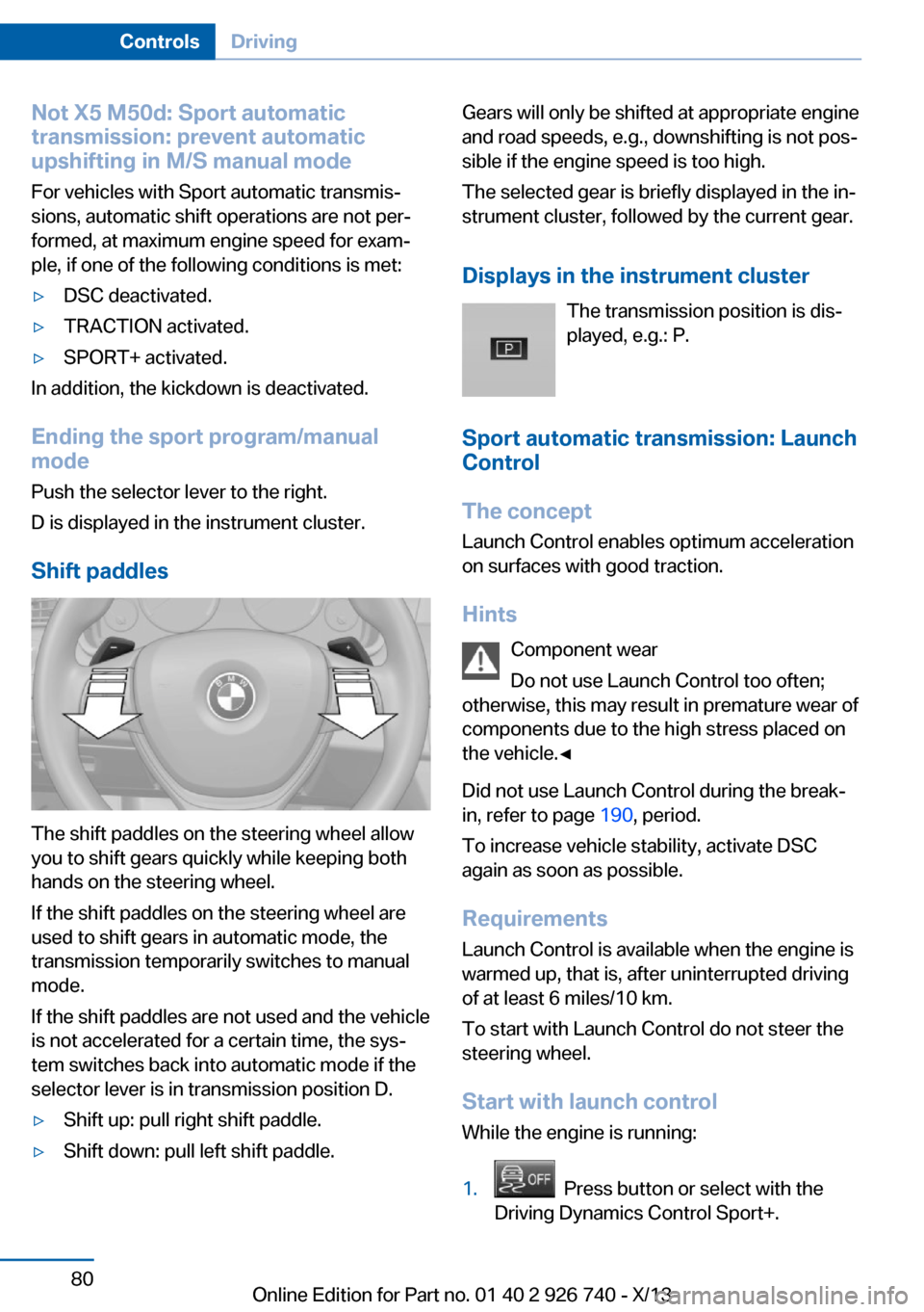
The shift paddles on the steering wheel allow
you to shift gears quickly while keeping both
hands on the steering wheel.
If the shift paddles on the steering wheel are
used to shift gears in automatic mode, the
transmission temporarily switches to manual
mode.
If the shift paddles are not used and the vehicle
is not accelerated for a certain time, the sys‐
tem switches back into automatic mode if the
selector lever is in transmission position D.
▷Shift up: pull right shift paddle.▷Shift down: pull left shift paddle.Gears will only be shifted at appropriate engine
and road speeds, e.g., downshifting is not pos‐
sible if the engine speed is too high.
The selected gear is briefly displayed in the in‐
strument cluster, followed by the current gear.
Displays in the instrument cluster The transmission position is dis‐
played, e.g.: P.
Sport automatic transmission: Launch Control
The concept
Launch Control enables optimum acceleration
on surfaces with good traction.
Hints Component wear
Do not use Launch Control too often;
otherwise, this may result in premature wear of
components due to the high stress placed on
the vehicle.◀
Did not use Launch Control during the break-
in, refer to page 190, period.
To increase vehicle stability, activate DSC
again as soon as possible.
Requirements
Launch Control is available when the engine is
warmed up, that is, after uninterrupted driving
of at least 6 miles/10 km.
To start with Launch Control do not steer the
steering wheel.
Start with launch controlWhile the engine is running:1. Press button or select with the
Driving Dynamics Control Sport+.
Seite 80ControlsDriving80
Online Edition for Part no. 01 40 2 926 740 - X/13
Page 81 of 265
TRACTION is displayed in the instrument
cluster and the indicator lamp for DSC OFF
lights up.2.Engaging the transmission position S3.With the left foot, forcefully press down on
the brake.4.Press and hold down the accelerator pedal
beyond the resistance point at the full
throttle position.
A flag symbol appears in the instrument
cluster.5.The starting engine speed adjusts. Within
3 seconds, release the brake.
Before using Launch Control, allow the trans‐
mission to cool down for approx. 5 minutes.
Launch Control adjusts to the surrounding
conditions, e.g., wet pavement, when used
again.
Seite 81DrivingControls81
Online Edition for Part no. 01 40 2 926 740 - X/13
Page 89 of 265
Coolant temperatureIf the coolant along with the engine becomes
too hot, a Check Control message is displayed.
Check the coolant level, refer to page 227.
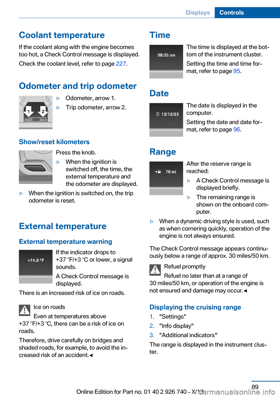
Odometer and trip odometer▷Odometer, arrow 1.▷Trip odometer, arrow 2.
Show/reset kilometers Press the knob.
▷When the ignition is
switched off, the time, the
external temperature and
the odometer are displayed.▷When the ignition is switched on, the trip
odometer is reset.
External temperature
External temperature warning If the indicator drops to
+37 ℉/+3 ℃ or lower, a signal
sounds.
A Check Control message is displayed.
There is an increased risk of ice on roads.
Ice on roads
Even at temperatures above
+37 ℉/+3 ℃, there can be a risk of ice on
roads.
Therefore, drive carefully on bridges and
shaded roads, for example, to avoid the in‐
creased risk of an accident.◀
Time
The time is displayed at the bot‐
tom of the instrument cluster.
Setting the time and time for‐
mat, refer to page 95.
Date The date is displayed in the
computer.
Setting the date and date for‐
mat, refer to page 96.
Range After the reserve range isreached:▷A Check Control message is
displayed briefly.▷The remaining range is
shown on the onboard com‐
puter.▷When a dynamic driving style is used, such
as when cornering quickly, operation of the
engine is not always ensured.
The Check Control message appears continu‐
ously below a range of approx. 30 miles/50 km.
Refuel promptly
Refuel no later than at a range of
30 miles/50 km, or operation of the engine is
not ensured and damage may occur.◀
Displaying the cruising range
1."Settings"2."Info display"3."Additional indicators"
The range is displayed in the instrument clus‐
ter.
Seite 89DisplaysControls89
Online Edition for Part no. 01 40 2 926 740 - X/13
Page 91 of 265
Automatic Service Request
Data regarding the service status or legally
mandated inspections of the vehicle are auto‐
matically transmitted to your service center
before a service due date.
You can check when your service center was
notified.1."Vehicle Info"2."Vehicle status"3.Open "Options".4."Last Service Request"
Gear shift indicator
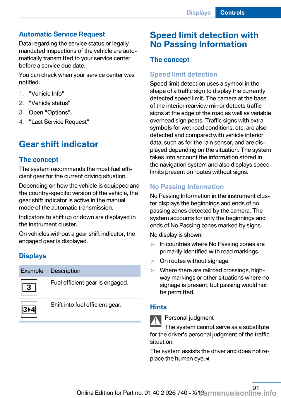
The conceptThe system recommends the most fuel effi‐
cient gear for the current driving situation.
Depending on how the vehicle is equipped and
the country-specific version of the vehicle, the
gear shift indicator is active in the manual
mode of the automatic transmission.
Indicators to shift up or down are displayed in
the instrument cluster.
On vehicles without a gear shift indicator, the
engaged gear is displayed.
Displays
ExampleDescriptionFuel efficient gear is engaged.Shift into fuel efficient gear.Speed limit detection with
No Passing Information
The concept
Speed limit detection Speed limit detection uses a symbol in the
shape of a traffic sign to display the currently
detected speed limit. The camera at the base
of the interior rearview mirror detects traffic
signs at the edge of the road as well as variable
overhead sign posts. Traffic signs with extra
symbols for wet road conditions, etc. are also
detected and compared with vehicle interior
data, such as for the rain sensor, and are dis‐
played depending on the situation. The system
takes into account the information stored in
the navigation system and also displays speed
limits present on routes without signs.
No Passing Information No Passing Information in the instrument clus‐
ter displays the beginnings and ends of no
passing zones detected by the camera. The
system accounts for only the beginnings and
ends of No Passing zones marked by signs.
No display is shown:▷In countries where No Passing zones are
primarily identified with road markings.▷On routes without signage.▷Where there are railroad crossings, high‐
way markings or other situations where no
signage is present, but passing would not
be permitted.
Hints
Personal judgment
The system cannot serve as a substitute
for the driver's personal judgment of the traffic
situation.
The system assists the driver and does not re‐
place the human eye.◀
Seite 91DisplaysControls91
Online Edition for Part no. 01 40 2 926 740 - X/13
Page 101 of 265
To avoid blinding oncoming traffic, the Adap‐
tive Light Control does not swivel to the driv‐
er's side when the vehicle is at a standstill.
When driving in reverse, only the cornering
lamp is active.
Self-leveling headlamps The self-leveling headlamps compensate for
acceleration and braking operations in order
not to blind the oncoming traffic and to achieve
optimum illumination of the roadway.
Malfunction
A Check Control message is displayed.
Adaptive light control is malfunctioning or has
failed. Have the system checked as soon as
possible.
High-beam Assistant The conceptWhen the low beams are switched on, this sys‐
tem automatically switches the high beams on
and off. The procedure is controlled by a sen‐
sor on the front of the interior rearview mirror.
The assistant ensures that the high beams are
switched on whenever the traffic situation al‐
lows. The driver can intervene at any time and
switch the high beams on and off as usual.
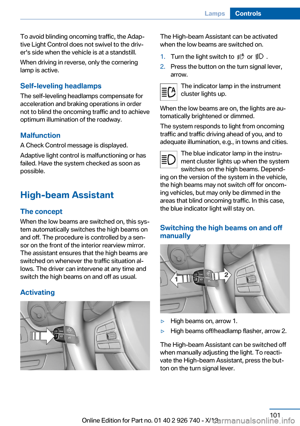
ActivatingThe High-beam Assistant can be activated
when the low beams are switched on.1.Turn the light switch to or .2.Press the button on the turn signal lever,
arrow.
The indicator lamp in the instrument
cluster lights up.
When the low beams are on, the lights are au‐
tomatically brightened or dimmed.
The system responds to light from oncoming
traffic and traffic driving ahead of you, and to
adequate illumination, e.g., in towns and cities.
The blue indicator lamp in the instru‐
ment cluster lights up when the system
switches on the high beams. Depend‐
ing on the version of the system in the vehicle, the high beams may not switch off for oncom‐
ing vehicles, but may only be dimmed in the
areas that blind oncoming traffic. In this case,
the blue indicator light will stay on.
Switching the high beams on and off
manually
▷High beams on, arrow 1.▷High beams off/headlamp flasher, arrow 2.
The High-beam Assistant can be switched off
when manually adjusting the light. To reacti‐
vate the High-beam Assistant, press the but‐
ton on the turn signal lever.
Seite 101LampsControls101
Online Edition for Part no. 01 40 2 926 740 - X/13
Page 105 of 265
Protective action
Airbags are not triggered in every impact situa‐
tion, e.g., in less severe accidents or rear-end
collisions.
Information on how to ensure the optimal
protective effect of the airbags▷Keep at a distance from the airbags.▷Always grasp the steering wheel on the
steering wheel rim, holding your hands at
the 3 o'clock and 9 o'clock positions, to
keep the danger of injury to your hands or
arms as low as possible if the airbag is trig‐
gered.▷There should be no people, animals, or ob‐
jects between an airbag and a person.▷Do not use the cover of the front airbag on
the front passenger side as a storage area.▷Keep the dashboard and window on the
front passenger side clear, i.e., do not
cover with adhesive labels or coverings,
and do not attach holders such as for navi‐
gation instruments and mobile phones.▷Make sure that the front passenger is sit‐
ting correctly, i.e., keeps his or her feet and
legs in the footwell; otherwise, leg injuries
can occur if the front airbag is triggered.▷Do not place slip covers, seat cushions or
other objects on the front passenger seat
that are not approved specifically for seats
with integrated side airbags.▷Do not hang pieces of clothing, such as
jackets, over the backrests.▷Make sure that occupants keep their heads
away from the side airbag and do not rest
against the head airbag; otherwise, injuries
can occur if the airbags are triggered.▷Do not remove the airbag restraint system.▷Do not remove the steering wheel.▷Do not apply adhesive materials to the air‐
bag cover panels, cover them or modify
them in any way.▷Never modify either the individual compo‐
nents or the wiring in the airbag system.
This also applies to steering wheel covers,
the dashboard, the seats, the roof pillars
and the sides of the headliner.◀
Even when all instructions are followed closely,
injury from contact with the airbags cannot be
ruled out in certain situations.
The ignition and inflation noise may lead to
short-term and, in most cases, temporary
hearing impairment in sensitive individuals.
In the case of a malfunction, deactivation
and after triggering of the airbags
Do not touch the individual components imme‐
diately after the system has been triggered;
otherwise, there is the danger of burns.
Only have the airbags checked, repaired or dis‐
mantled and the airbag generator scrapped by
the service center or a workshop that has the
necessary authorization for handling explo‐
sives.
Non-professional attempts to service the sys‐
tem could lead to failure in an emergency or
undesired triggering of the airbag, either of
which could result in injury.◀
Warnings and information on the airbags are
also found on the sun visors.
Functional readiness of the airbag
system
When the ignition is switched on, the
warning lamp in the instrument cluster
lights up briefly and thereby indicates
the operational readiness of the entire airbag
system and the belt tensioner.
Airbag system malfunctioning
▷Warning lamp does not come on when the
ignition is turned on.▷The warning lamp lights up continuously.Seite 105SafetyControls105
Online Edition for Part no. 01 40 2 926 740 - X/13
Page 106 of 265
When there is a malfunction, have the
airbag system checked immediately
When there is a malfunction, have the airbag
system checked immediately; otherwise, there
is a risk that the system does not function as
expected in the event of an accident despite
corresponding severity of the accident.◀
Automatic deactivation of the front passenger airbags
The system determines whether the front pas‐
senger seat is occupied by measuring the re‐
sistance of the human body.
The front, knee, and side airbag on the front passenger side are activated or deactivated
accordingly.
Leave feet in the footwell
Make sure that the front passenger
keeps his or her feet in the footwell; otherwise,
the front passenger airbags may not function properly.◀
Child restraint fixing system in the front
passenger seat
Before transporting a child on the front pas‐
senger seat, refer to the safety notes and in‐
structions under Children on the front passen‐
ger seat.◀
Malfunction of the automaticdeactivation system
When transporting older children and adults,
the front passenger airbags may be deacti‐
vated in certain sitting positions. In this case,
the indicator lamp for the front passenger air‐
bags lights up.
In this case, change the sitting position so that
the front passenger airbags are activated and
the indicator lamp goes out.
If it is not possible to activate the airbags, have
the person sit in the rear.
To make sure that the occupied seat cushion
can be evaluated correctly▷Do not attach covers, cushions, ball mats
or other items to the front passenger seat
unless they are specifically recommended
by the manufacturer of your vehicle.▷Do not place any electronic devices on the
passenger seat if a child restraint system is
to be installed on it.▷Do not place objects under the seat that
could press against the seat from below.▷No moisture in or on the seat.
Indicator lamp for the front passenger
airbags
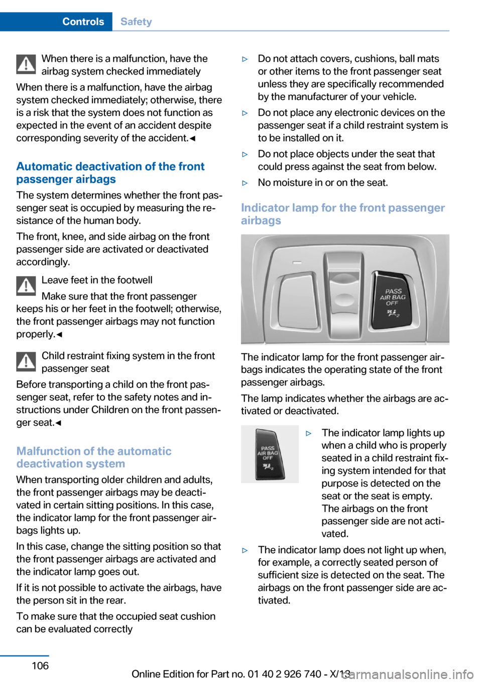
The indicator lamp for the front passenger air‐
bags indicates the operating state of the front
passenger airbags.
The lamp indicates whether the airbags are ac‐
tivated or deactivated.
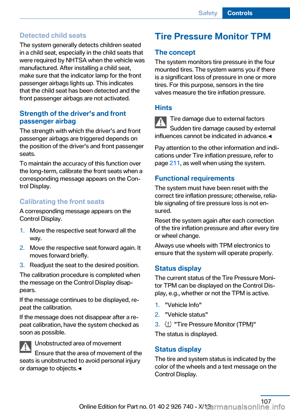
▷The indicator lamp lights up
when a child who is properly
seated in a child restraint fix‐
ing system intended for that
purpose is detected on the
seat or the seat is empty.
The airbags on the front
passenger side are not acti‐
vated.▷The indicator lamp does not light up when,
for example, a correctly seated person of
sufficient size is detected on the seat. The
airbags on the front passenger side are ac‐
tivated.Seite 106ControlsSafety106
Online Edition for Part no. 01 40 2 926 740 - X/13
Page 107 of 265
Detected child seatsThe system generally detects children seated
in a child seat, especially in the child seats that
were required by NHTSA when the vehicle was
manufactured. After installing a child seat,
make sure that the indicator lamp for the front
passenger airbags lights up. This indicates that the child seat has been detected and the
front passenger airbags are not activated.
Strength of the driver's and front
passenger airbag
The strength with which the driver's and front
passenger airbags are triggered depends on
the position of the driver's and front passenger
seats.
To maintain the accuracy of this function over
the long-term, calibrate the front seats when a
corresponding message appears on the Con‐
trol Display.
Calibrating the front seats A corresponding message appears on the
Control Display.1.Move the respective seat forward all the
way.2.Move the respective seat forward again. It
moves forward briefly.3.Readjust the seat to the desired position.
The calibration procedure is completed when
the message on the Control Display disap‐
pears.
If the message continues to be displayed, re‐
peat the calibration.
If the message does not disappear after a re‐
peat calibration, have the system checked as
soon as possible.
Unobstructed area of movement
Ensure that the area of movement of the
seats is unobstructed to avoid personal injury
or damage to objects.◀
Tire Pressure Monitor TPM
The concept The system monitors tire pressure in the four
mounted tires. The system warns you if there
is a significant loss of pressure in one or more
tires. For this purpose, sensors in the tire
valves measure the tire inflation pressure.
Hints Tire damage due to external factors
Sudden tire damage caused by external
influences cannot be indicated in advance.◀
Pay attention to the other information and indi‐
cations under Tire inflation pressure, refer to
page 211, as well when using the system.
Functional requirements
The system must have been reset with the
correct tire inflation pressure; otherwise, relia‐
ble signaling of tire pressure loss is not en‐
sured.
Reset the system again after each correction
of the tire inflation pressure and after every tire
or wheel change.
Always use wheels with TPM electronics to
ensure that the system will operate properly.
Status display The current status of the Tire Pressure Moni‐
tor TPM can be displayed on the Control Dis‐
play, e.g., whether or not the TPM is active.1."Vehicle Info"2."Vehicle status"3. "Tire Pressure Monitor (TPM)"
The status is displayed.
Status display The tire and system status is indicated by the
color of the wheels and a text message on the
Control Display.
Seite 107SafetyControls107
Online Edition for Part no. 01 40 2 926 740 - X/13