clock BMW X5 2014 F15 Owner's Manual
[x] Cancel search | Manufacturer: BMW, Model Year: 2014, Model line: X5, Model: BMW X5 2014 F15Pages: 265, PDF Size: 6.2 MB
Page 22 of 265
▷For the input of upper/lower case letters
and numbers, it may be necessary to
switch via the controller to the correspond‐
ing Input mode, refer to page 25, e.g.
when the spelling of upper and lower case
letters is identical.▷Enter characters as they are displayed on
the Control Display.▷Always enter accompanying signs, such as
accents or periods so that the letter can be
clearly recognized. The possibility of input
depends on the set language. Where nec‐
essary, enter special characters via the
controller.▷To delete a character, slide to the left on
the touchpad.▷To enter a blank space, slide to the right in
the center of the touchpad.▷To enter a hyphen, slide to the right in the
upper area of the touchpad.▷To enter an underscore, slide to the right in
the lower area of the touchpad.
Using interactive map and Internet
The interactive map in the navigation system
and Internet sites can be moved via the touch‐
pad.
FunctionControlsMove interactive map
or Internet sites.Slide in the corre‐
sponding direction.Enlarge/shrink interac‐
tive map or Internet
sites.Drag inwards or
outwards on the
touchpad with the
fingers.Display the menu or
open a link in the Inter‐
net.Tap once.Changing settings
Settings on the control display, such as the
volume, can be made via the touchpad. To do
this slide to the left or right accordingly.
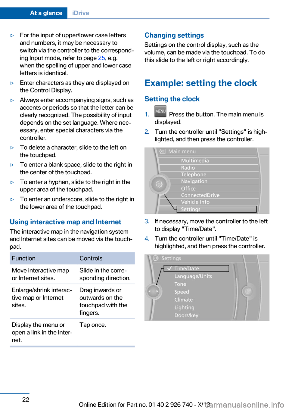
Example: setting the clock Setting the clock1. Press the button. The main menu is
displayed.2.Turn the controller until "Settings" is high‐
lighted, and then press the controller.3.If necessary, move the controller to the left
to display "Time/Date".4.Turn the controller until "Time/Date" is
highlighted, and then press the controller.Seite 22At a glanceiDrive22
Online Edition for Part no. 01 40 2 926 740 - X/13
Page 84 of 265
Electronic displays
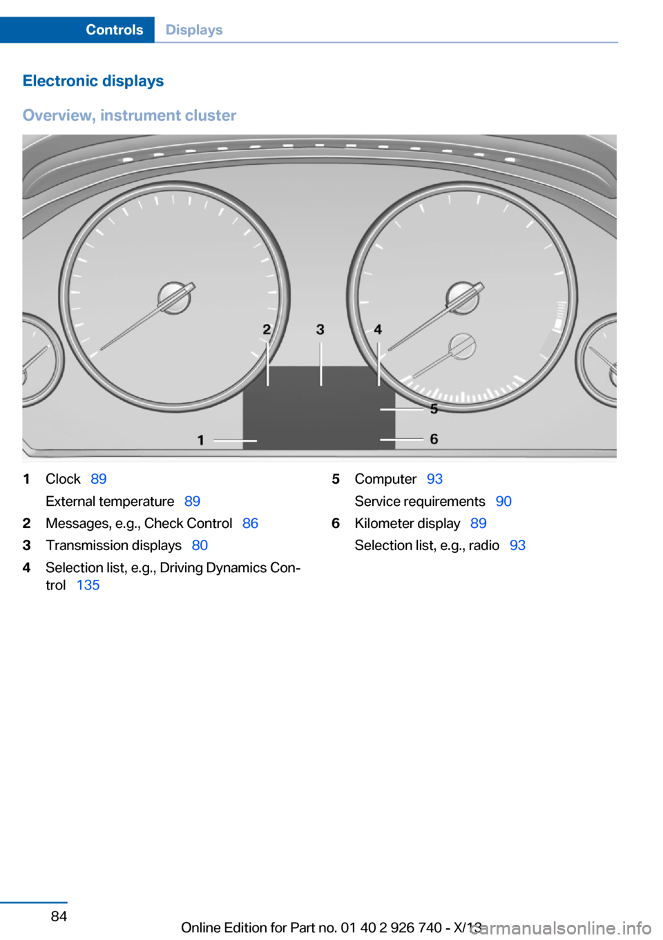
Overview, instrument cluster1Clock 89
External temperature 892Messages, e.g., Check Control 863Transmission displays 804Selection list, e.g., Driving Dynamics Con‐
trol 1355Computer 93
Service requirements 906Kilometer display 89
Selection list, e.g., radio 93Seite 84ControlsDisplays84
Online Edition for Part no. 01 40 2 926 740 - X/13
Page 105 of 265
Protective action
Airbags are not triggered in every impact situa‐
tion, e.g., in less severe accidents or rear-end
collisions.
Information on how to ensure the optimal
protective effect of the airbags▷Keep at a distance from the airbags.▷Always grasp the steering wheel on the
steering wheel rim, holding your hands at
the 3 o'clock and 9 o'clock positions, to
keep the danger of injury to your hands or
arms as low as possible if the airbag is trig‐
gered.▷There should be no people, animals, or ob‐
jects between an airbag and a person.▷Do not use the cover of the front airbag on
the front passenger side as a storage area.▷Keep the dashboard and window on the
front passenger side clear, i.e., do not
cover with adhesive labels or coverings,
and do not attach holders such as for navi‐
gation instruments and mobile phones.▷Make sure that the front passenger is sit‐
ting correctly, i.e., keeps his or her feet and
legs in the footwell; otherwise, leg injuries
can occur if the front airbag is triggered.▷Do not place slip covers, seat cushions or
other objects on the front passenger seat
that are not approved specifically for seats
with integrated side airbags.▷Do not hang pieces of clothing, such as
jackets, over the backrests.▷Make sure that occupants keep their heads
away from the side airbag and do not rest
against the head airbag; otherwise, injuries
can occur if the airbags are triggered.▷Do not remove the airbag restraint system.▷Do not remove the steering wheel.▷Do not apply adhesive materials to the air‐
bag cover panels, cover them or modify
them in any way.▷Never modify either the individual compo‐
nents or the wiring in the airbag system.
This also applies to steering wheel covers,
the dashboard, the seats, the roof pillars
and the sides of the headliner.◀
Even when all instructions are followed closely,
injury from contact with the airbags cannot be
ruled out in certain situations.
The ignition and inflation noise may lead to
short-term and, in most cases, temporary
hearing impairment in sensitive individuals.
In the case of a malfunction, deactivation
and after triggering of the airbags
Do not touch the individual components imme‐
diately after the system has been triggered;
otherwise, there is the danger of burns.
Only have the airbags checked, repaired or dis‐
mantled and the airbag generator scrapped by
the service center or a workshop that has the
necessary authorization for handling explo‐
sives.
Non-professional attempts to service the sys‐
tem could lead to failure in an emergency or
undesired triggering of the airbag, either of
which could result in injury.◀
Warnings and information on the airbags are
also found on the sun visors.
Functional readiness of the airbag
system
When the ignition is switched on, the
warning lamp in the instrument cluster
lights up briefly and thereby indicates
the operational readiness of the entire airbag
system and the belt tensioner.
Airbag system malfunctioning
▷Warning lamp does not come on when the
ignition is turned on.▷The warning lamp lights up continuously.Seite 105SafetyControls105
Online Edition for Part no. 01 40 2 926 740 - X/13
Page 129 of 265
rectly. Therefore, make sure that the driver is
rested and alert; otherwise, risks may be de‐
tected too late and an accident be caused as a
result.◀
Function
The system is activated each time the engine
is started and cannot be switched off.
After travel has begun, the system is trained
about the driver, so that increasing lack of
alertness or fatigue can be detected.
This procedure takes the following criteria into
account:▷Personal driving style, for example, steer‐
ing behavior.▷Driving conditions, for example, length of
trip.
Starting at approximately 43 mph/70 km/h, the
system is active and can display a recommen‐
dation to take a break.
Break recommendation
If the driver becomes increasingly less alert or
fatigued, a message is displayed in the Control
Display with the recommendation to take a
break.
A recommendation to take a break is displayed
only once during an uninterrupted trip.
After a break, another recommendation to take
a break cannot be displayed until after approxi‐
mately 45 minutes.
System limits
The function may be limited in the following
situations, for instance, and will either output
an incorrect warning or no warning at all:
▷When the clock is set incorrectly.▷When the vehicle speed is mainly below
about 43 mph/70 km/h.▷With a sporty driving style, such as during
rapid acceleration or when cornering
quickly.▷In active driving situations, such as when
changing lanes frequently.▷When the road surface is poor.▷In the event of strong side winds.
PreCrash
The concept With this system critical driving situations that
might result in an accident can be detected
above a speed of approx. 20 mph/30 km/h. In these situations, preventative protection
measures are automatically undertaken to
minimize the risk in the event of an accident as
much as possible.
Critical driving situations may include:
▷Full brake applications.
If the vehicle includes the collision warning or
collision warning with braking feature, impend‐
ing collisions with vehicles driving ahead or
stopped in front of you can also be detected
within the system's range.
Note Personal responsibility
The system cannot possibly serve as a
substitute for the driver's personal judgment of
the traffic situation. The system may not al‐
ways detect critical situations reliably and in a
timely manner. Adapt speed to traffic situation
and drive alertly; otherwise, a risk to safety may
result.◀
Function
After the safety belt is buckled, the front belts
are automatically pretensioned once after the
vehicle is driven is away.
In critical driving situations, the following indi‐
vidual functions become active as needed:
▷The front belts are automatically preten‐
sioned.▷Automatic closing of the windows.Seite 129SafetyControls129
Online Edition for Part no. 01 40 2 926 740 - X/13
Page 204 of 265
RefuelingVehicle equipment
All standard, country-specific and optional
equipment that is offered in the model series is
described in this chapter. Therefore, equip‐
ment is also described that is not available in a
vehicle, e. g., because of the selected optional
equipment or country variant. This also applies
for safety-related functions and systems.
Hints Refuel promptly
Refuel no later than at a range of
30 miles/50 km, or operation of the engine is
not ensured and damage may occur.◀
Diesel engines The filler neck is designed for refueling at die‐
sel fuel pumps.
Fuel cap
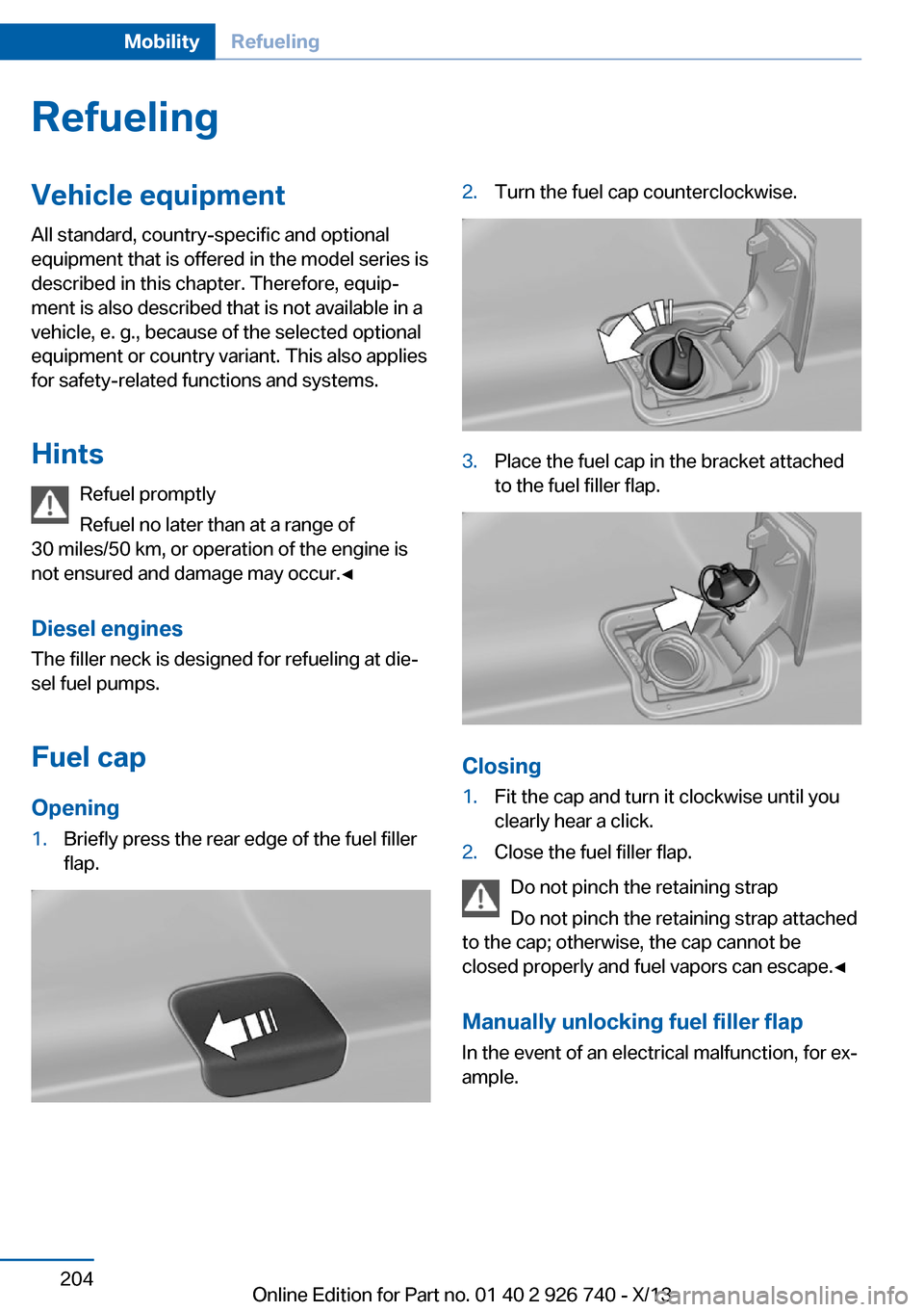
Opening1.Briefly press the rear edge of the fuel filler
flap.2.Turn the fuel cap counterclockwise.3.Place the fuel cap in the bracket attached
to the fuel filler flap.
Closing
1.Fit the cap and turn it clockwise until you
clearly hear a click.2.Close the fuel filler flap.
Do not pinch the retaining strap
Do not pinch the retaining strap attached
to the cap; otherwise, the cap cannot be
closed properly and fuel vapors can escape.◀
Manually unlocking fuel filler flap In the event of an electrical malfunction, for ex‐
ample.
Seite 204MobilityRefueling204
Online Edition for Part no. 01 40 2 926 740 - X/13
Page 209 of 265
Suitable Diesel exhaust fluid▷Preferred: BMW Diesel Exhaust Fluid. With
this bottle and its special adapter, Diesel
exhaust fluid can be replenished simply
and safely.
▷Alternative: NOx reduction agent AUS 32
Diesel exhaust fluid can be purchased at your
Service Center.
Refill quantity
When the Reserve display starts, add at least 2
bottles of reducing agent.
This corresponds to approx. 1 gallon.
Tank for reducing agent
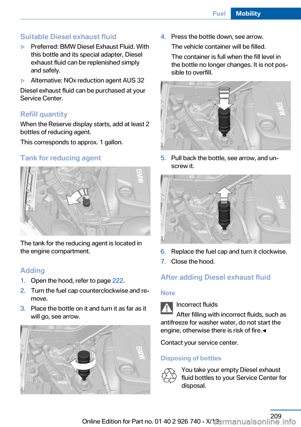
The tank for the reducing agent is located in
the engine compartment.
Adding
1.Open the hood, refer to page 222.2.Turn the fuel cap counterclockwise and re‐
move.
3.Place the bottle on it and turn it as far as it
will go, see arrow.
4.Press the bottle down, see arrow.
The vehicle container will be filled.
The container is full when the fill level in
the bottle no longer changes. It is not pos‐
sible to overfill.
5.Pull back the bottle, see arrow, and un‐
screw it.
6.Replace the fuel cap and turn it clockwise.7.Close the hood.
After adding Diesel exhaust fluid
Note
Incorrect fluids
After filling with incorrect fluids, such as
antifreeze for washer water, do not start the
engine, otherwise there is risk of fire.◀
Contact your service center.
Disposing of bottles
You take your empty Diesel exhaust
fluid bottles to your Service Center for
disposal.
Seite 209FuelMobility209
Online Edition for Part no. 01 40 2 926 740 - X/13
Page 227 of 265
CoolantVehicle equipmentAll standard, country-specific and optional
equipment that is offered in the model series is
described in this chapter. Therefore, equip‐
ment is also described that is not available in a
vehicle, e. g., because of the selected optional
equipment or country variant. This also applies
for safety-related functions and systems.
Hints Danger of burns from hot engine
Do not open the cooling system while
the engine is hot; otherwise, escaping coolant
may cause burns.◀
Suitable additives
Only use suitable additives; otherwise,
engine damage may occur. The additives are
harmful to your health.◀
Coolant consists of water and additives.
Not all commercially available additives are
suitable for the vehicle. Information about the
suitable additives are available from the service
center.
Coolant level
If there is no Min. and Max. mark in the filler
neck of the coolant reservoir, have the coolant
level checked if necessary by your service cen‐
ter and add coolant as needed.
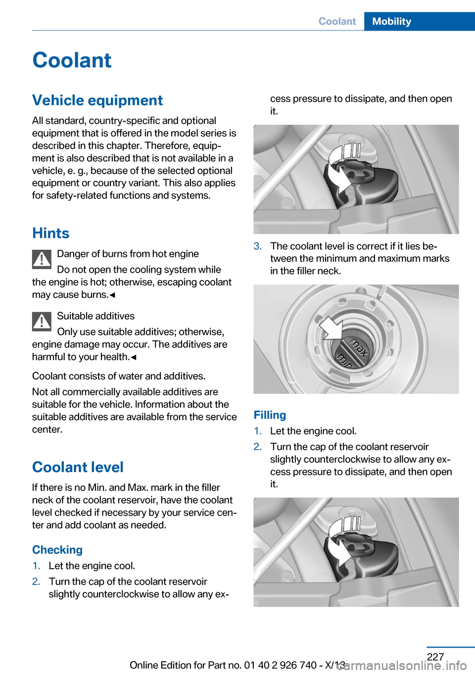
Checking1.Let the engine cool.2.Turn the cap of the coolant reservoir
slightly counterclockwise to allow any ex‐cess pressure to dissipate, and then open
it.3.The coolant level is correct if it lies be‐
tween the minimum and maximum marks
in the filler neck.
Filling
1.Let the engine cool.2.Turn the cap of the coolant reservoir
slightly counterclockwise to allow any ex‐
cess pressure to dissipate, and then open
it.Seite 227CoolantMobility227
Online Edition for Part no. 01 40 2 926 740 - X/13
Page 234 of 265
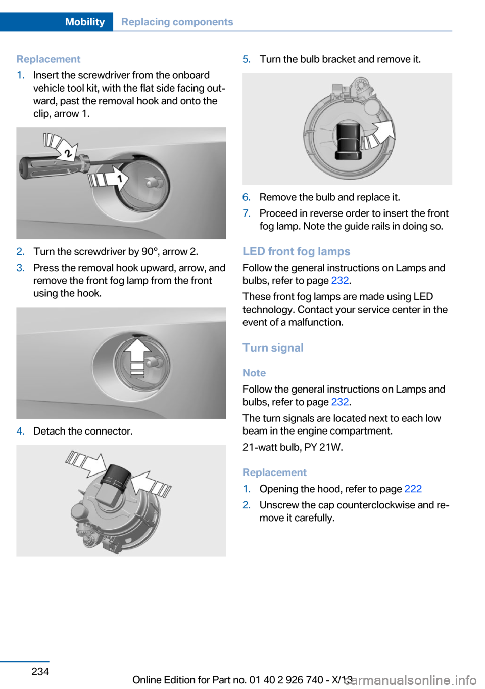
Replacement1.Insert the screwdriver from the onboard
vehicle tool kit, with the flat side facing out‐
ward, past the removal hook and onto the
clip, arrow 1.2.Turn the screwdriver by 90°, arrow 2.3.Press the removal hook upward, arrow, and
remove the front fog lamp from the front
using the hook.4.Detach the connector.5.Turn the bulb bracket and remove it.6.Remove the bulb and replace it.7.Proceed in reverse order to insert the front
fog lamp. Note the guide rails in doing so.
LED front fog lamps
Follow the general instructions on Lamps and
bulbs, refer to page 232.
These front fog lamps are made using LED
technology. Contact your service center in the
event of a malfunction.
Turn signal
Note
Follow the general instructions on Lamps and
bulbs, refer to page 232.
The turn signals are located next to each low
beam in the engine compartment.
21-watt bulb, PY 21W.
Replacement
1.Opening the hood, refer to page 2222.Unscrew the cap counterclockwise and re‐
move it carefully.Seite 234MobilityReplacing components234
Online Edition for Part no. 01 40 2 926 740 - X/13
Page 235 of 265
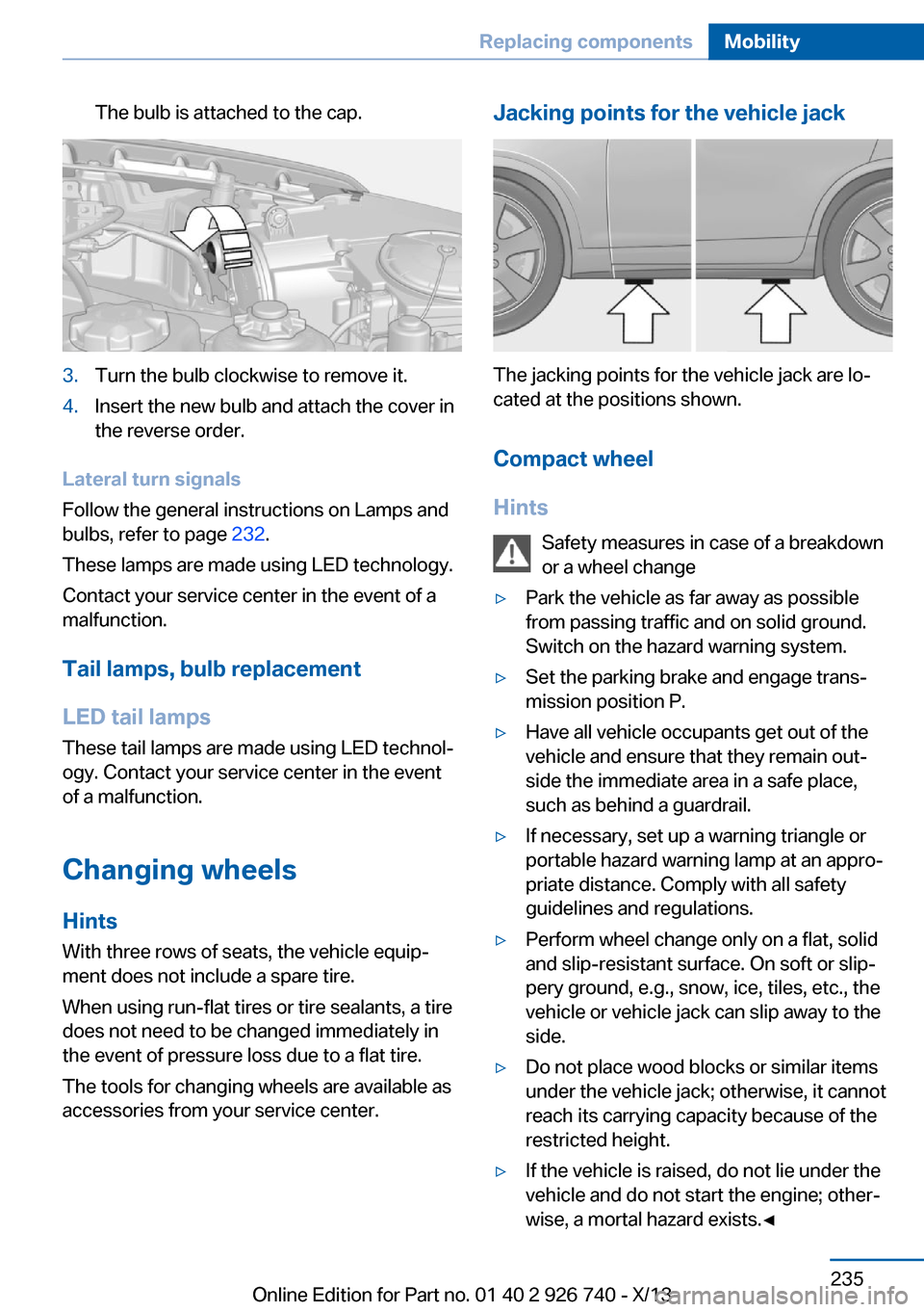
The bulb is attached to the cap.3.Turn the bulb clockwise to remove it.4.Insert the new bulb and attach the cover in
the reverse order.
Lateral turn signals
Follow the general instructions on Lamps and
bulbs, refer to page 232.
These lamps are made using LED technology.
Contact your service center in the event of a
malfunction.
Tail lamps, bulb replacement
LED tail lamps
These tail lamps are made using LED technol‐
ogy. Contact your service center in the event
of a malfunction.
Changing wheels
Hints
With three rows of seats, the vehicle equip‐
ment does not include a spare tire.
When using run-flat tires or tire sealants, a tire
does not need to be changed immediately in
the event of pressure loss due to a flat tire.
The tools for changing wheels are available as
accessories from your service center.
Jacking points for the vehicle jack
The jacking points for the vehicle jack are lo‐
cated at the positions shown.
Compact wheel
Hints Safety measures in case of a breakdownor a wheel change
▷Park the vehicle as far away as possible
from passing traffic and on solid ground.
Switch on the hazard warning system.▷Set the parking brake and engage trans‐
mission position P.▷Have all vehicle occupants get out of the
vehicle and ensure that they remain out‐
side the immediate area in a safe place,
such as behind a guardrail.▷If necessary, set up a warning triangle or
portable hazard warning lamp at an appro‐
priate distance. Comply with all safety
guidelines and regulations.▷Perform wheel change only on a flat, solid
and slip-resistant surface. On soft or slip‐
pery ground, e.g., snow, ice, tiles, etc., the
vehicle or vehicle jack can slip away to the
side.▷Do not place wood blocks or similar items
under the vehicle jack; otherwise, it cannot
reach its carrying capacity because of the
restricted height.▷If the vehicle is raised, do not lie under the
vehicle and do not start the engine; other‐
wise, a mortal hazard exists.◀Seite 235Replacing componentsMobility235
Online Edition for Part no. 01 40 2 926 740 - X/13
Page 240 of 265
if it can be established, are transmitted to
the BMW Response Center.▷If the LED is flashing, but the BMW Re‐
sponse Center can no longer be heard via
the speaker, you can nevertheless still be
heard for the BMW Response Center.
Initiating an Emergency Request
automatically
Under certain conditions, an Emergency Re‐
quest is automatically initiated immediately af‐
ter a severe accident. Automatic Collision Noti‐
fication is not affected by pressing the SOS
button.
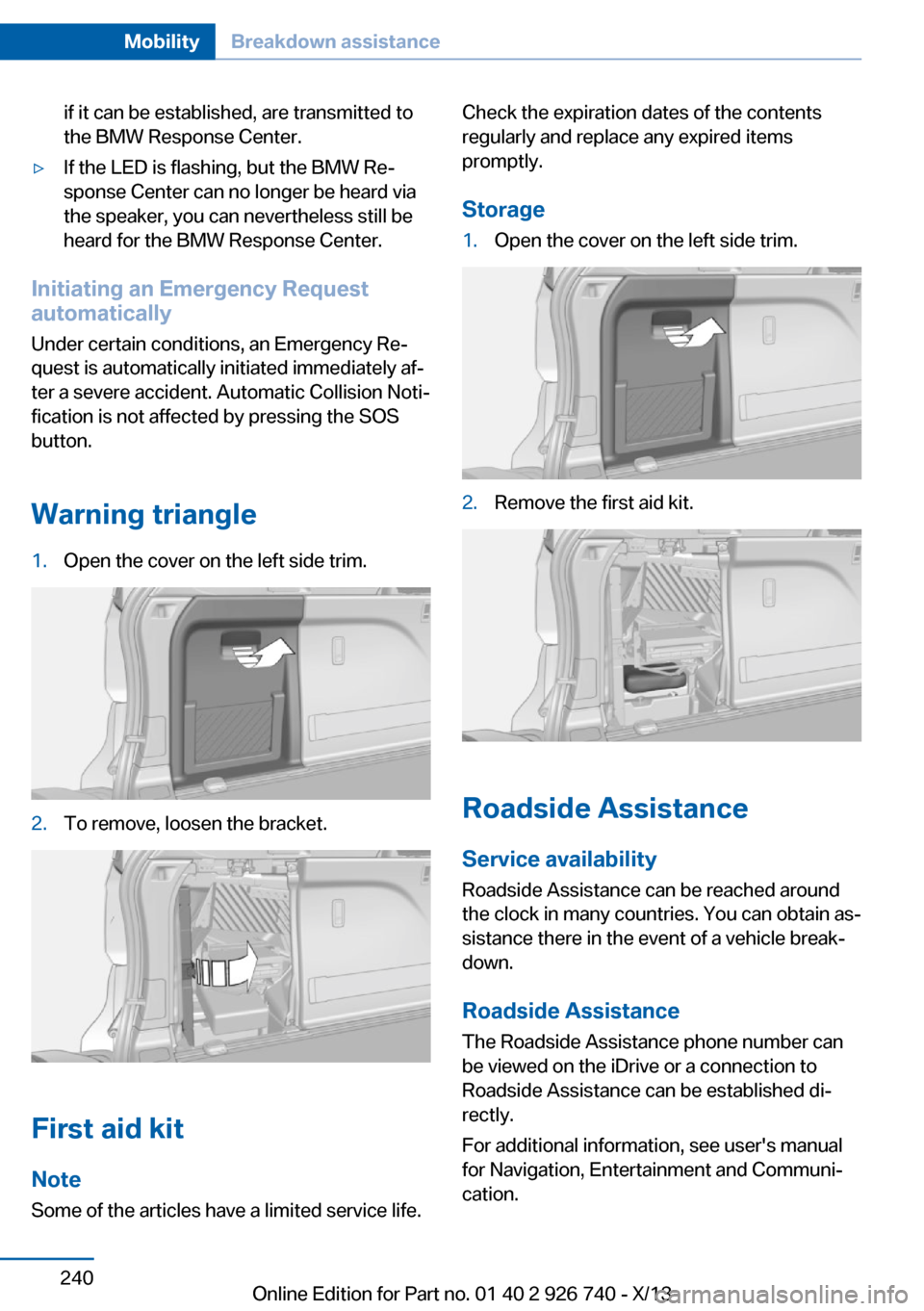
Warning triangle
1.Open the cover on the left side trim.2.To remove, loosen the bracket.
First aid kit Note
Some of the articles have a limited service life.
Check the expiration dates of the contents
regularly and replace any expired items
promptly.
Storage1.Open the cover on the left side trim.2.Remove the first aid kit.
Roadside Assistance
Service availability Roadside Assistance can be reached around
the clock in many countries. You can obtain as‐
sistance there in the event of a vehicle break‐
down.
Roadside Assistance The Roadside Assistance phone number can
be viewed on the iDrive or a connection to
Roadside Assistance can be established di‐
rectly.
For additional information, see user's manual
for Navigation, Entertainment and Communi‐
cation.
Seite 240MobilityBreakdown assistance240
Online Edition for Part no. 01 40 2 926 740 - X/13