Side view BMW X5 2015 F15 Owner's Guide
[x] Cancel search | Manufacturer: BMW, Model Year: 2015, Model line: X5, Model: BMW X5 2015 F15Pages: 275, PDF Size: 6.46 MB
Page 162 of 275
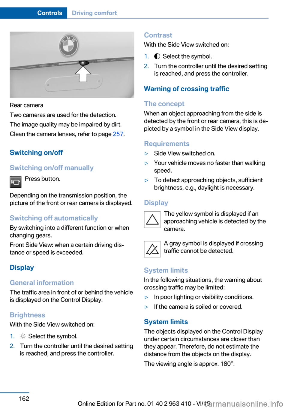
Rear camera
Two cameras are used for the detection.
The image quality may be impaired by dirt.
Clean the camera lenses, refer to page 257.
Switching on/off
Switching on/off manually Press button.
Depending on the transmission position, the
picture of the front or rear camera is displayed.
Switching off automatically By switching into a different function or when
changing gears.
Front Side View: when a certain driving dis‐
tance or speed is exceeded.
Display
General information
The traffic area in front of or behind the vehicle
is displayed on the Control Display.
Brightness With the Side View switched on:
1. Select the symbol.2.Turn the controller until the desired setting
is reached, and press the controller.Contrast
With the Side View switched on:1. Select the symbol.2.Turn the controller until the desired setting
is reached, and press the controller.
Warning of crossing traffic
The concept When an object approaching from the side is
detected by the front or rear camera, this is de‐
picted by a symbol in the Side View display.
Requirements
▷Side View switched on.▷Your vehicle moves no faster than walking
speed.▷To detect approaching objects, sufficient
brightness, e.g., daylight is necessary.
Display
The yellow symbol is displayed if anapproaching vehicle is detected by the
camera.
A gray symbol is displayed if crossing
traffic cannot be detected.
System limits
In the following situations, the warning about
crossing traffic may be limited:
▷In poor lighting or visibility conditions.▷If the camera is soiled or covered.
System limits
The objects displayed on the Control Display
under certain circumstances are closer than
they appear. Therefore, do not estimate the
distance from the objects on the display.
The viewing angle is approx. 180°.
Seite 162ControlsDriving comfort162
Online Edition for Part no. 01 40 2 963 410 - VI/15
Page 163 of 275
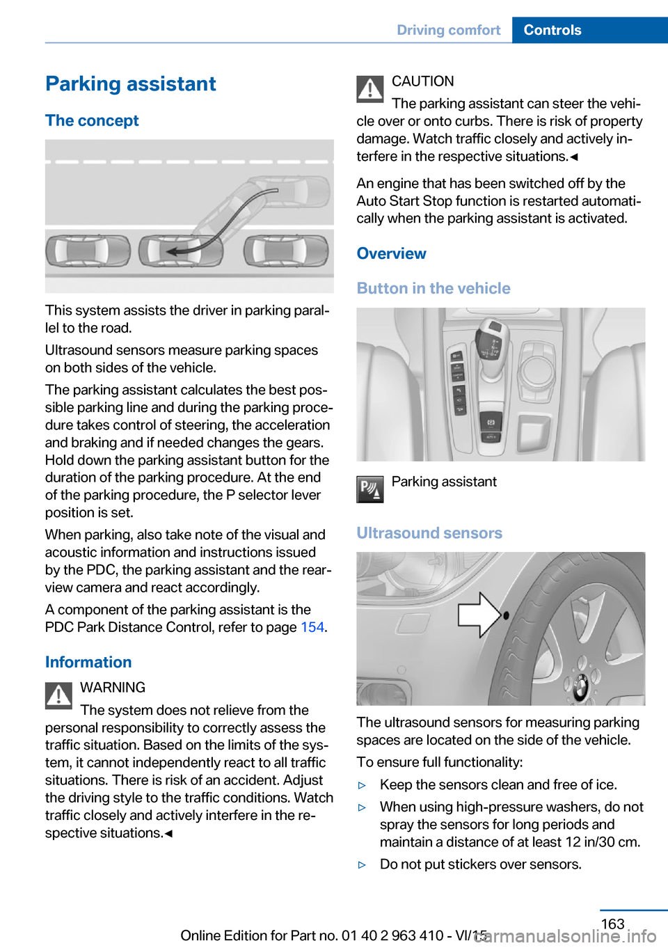
Parking assistantThe concept
This system assists the driver in parking paral‐
lel to the road.
Ultrasound sensors measure parking spaces
on both sides of the vehicle.
The parking assistant calculates the best pos‐
sible parking line and during the parking proce‐
dure takes control of steering, the acceleration
and braking and if needed changes the gears.
Hold down the parking assistant button for the
duration of the parking procedure. At the end
of the parking procedure, the P selector lever
position is set.
When parking, also take note of the visual and
acoustic information and instructions issued
by the PDC, the parking assistant and the rear‐
view camera and react accordingly.
A component of the parking assistant is the
PDC Park Distance Control, refer to page 154.
Information WARNING
The system does not relieve from the
personal responsibility to correctly assess the
traffic situation. Based on the limits of the sys‐
tem, it cannot independently react to all traffic
situations. There is risk of an accident. Adjust
the driving style to the traffic conditions. Watch
traffic closely and actively interfere in the re‐
spective situations.◀
CAUTION
The parking assistant can steer the vehi‐
cle over or onto curbs. There is risk of property
damage. Watch traffic closely and actively in‐
terfere in the respective situations.◀
An engine that has been switched off by the
Auto Start Stop function is restarted automati‐
cally when the parking assistant is activated.
Overview
Button in the vehicle
Parking assistant
Ultrasound sensors
The ultrasound sensors for measuring parking
spaces are located on the side of the vehicle.
To ensure full functionality:
▷Keep the sensors clean and free of ice.▷When using high-pressure washers, do not
spray the sensors for long periods and
maintain a distance of at least 12 in/30 cm.▷Do not put stickers over sensors.Seite 163Driving comfortControls163
Online Edition for Part no. 01 40 2 963 410 - VI/15
Page 171 of 275
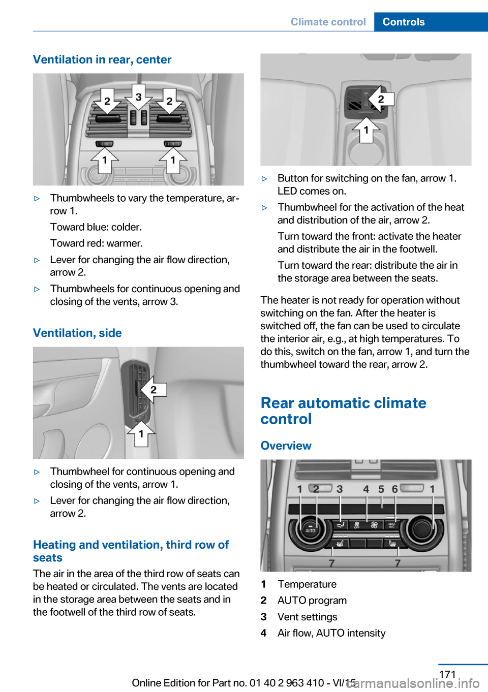
Ventilation in rear, center▷Thumbwheels to vary the temperature, ar‐
row 1.
Toward blue: colder.
Toward red: warmer.▷Lever for changing the air flow direction,
arrow 2.▷Thumbwheels for continuous opening and
closing of the vents, arrow 3.
Ventilation, side
▷Thumbwheel for continuous opening and
closing of the vents, arrow 1.▷Lever for changing the air flow direction,
arrow 2.
Heating and ventilation, third row of
seats
The air in the area of the third row of seats can
be heated or circulated. The vents are located
in the storage area between the seats and in
the footwell of the third row of seats.
▷Button for switching on the fan, arrow 1.
LED comes on.▷Thumbwheel for the activation of the heat
and distribution of the air, arrow 2.
Turn toward the front: activate the heater
and distribute the air in the footwell.
Turn toward the rear: distribute the air in
the storage area between the seats.
The heater is not ready for operation without
switching on the fan. After the heater is
switched off, the fan can be used to circulate
the interior air, e.g., at high temperatures. To
do this, switch on the fan, arrow 1, and turn the
thumbwheel toward the rear, arrow 2.
Rear automatic climate
control
Overview
1Temperature2AUTO program3Vent settings4Air flow, AUTO intensitySeite 171Climate controlControls171
Online Edition for Part no. 01 40 2 963 410 - VI/15
Page 176 of 275
4.Likewise, press and hold the button of the
desired function on the hand-held trans‐
mitter.5.Release both buttons as soon as the inte‐
rior rearview mirror LED flashes more rap‐
idly. The LED flashing faster indicates that
the button on the interior rearview mirror
has been programmed. The system can
then be controlled by the button on the in‐
terior rearview mirror.
If the LED does not flash faster after at
least 60 seconds, change the distance and
repeat the step. Several more attempts at
different distances may be necessary. Wait
at least 15 seconds between attempts.
Canada: if programming with the hand-
held transmitter was interrupted, hold
down the interior rearview mirror button
and repeatedly press and release the
hand-held transmitter button for 2 sec‐
onds.
Controls
WARNING
Body parts can be jammed when operat‐
ing remote-controlled systems, e.g. the garage
door, using the universal garage door opener. There is risk of injuries or risk of property dam‐
age. Make sure that the area of movement of
the respective system is clear during program‐
ming and operation. Also follow the safety in‐
structions of the hand-held transmitter.◀
The system, such as the garage door, can be
operated using the button on the interior rear‐
view mirror while the engine is running or when
the ignition is started. To do this, hold down
the button within receiving range of the system
until the function is activated. The interior rear‐
view mirror LED stays lit while the wireless sig‐
nal is being transmitted.
Deleting stored functions Press and hold the left and right button on the
interior rearview mirror simultaneously for ap‐
proximately 20 seconds until the LED flashes
rapidly. All stored functions are deleted. The
functions cannot be deleted individually.
Sun visor Glare shieldFold the sun visor down or up.
Glare shield from the side
Folding out1.Fold the sun visor down.2.Unhook it from the holder and swing it to
the side.3.Move it back to the desired position.
Folding up
Proceed in the reverse order to close the sun
visor.
Vanity mirror A vanity mirror is located in the sun visor be‐
hind a cover. When the cover is opened, the
mirror lighting switches on.
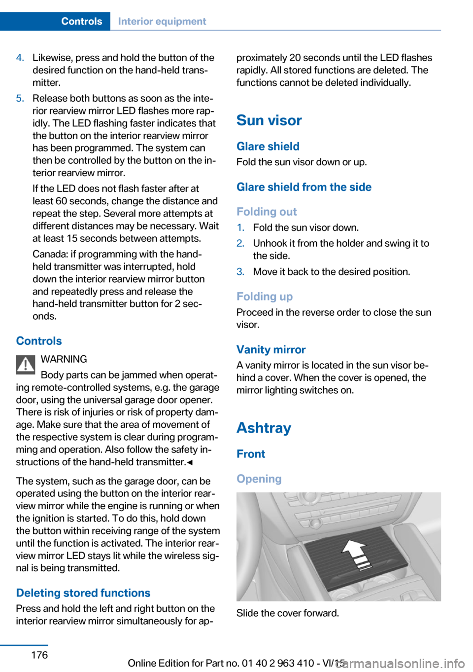
Ashtray
Front
Opening
Slide the cover forward.
Seite 176ControlsInterior equipment176
Online Edition for Part no. 01 40 2 963 410 - VI/15
Page 184 of 275
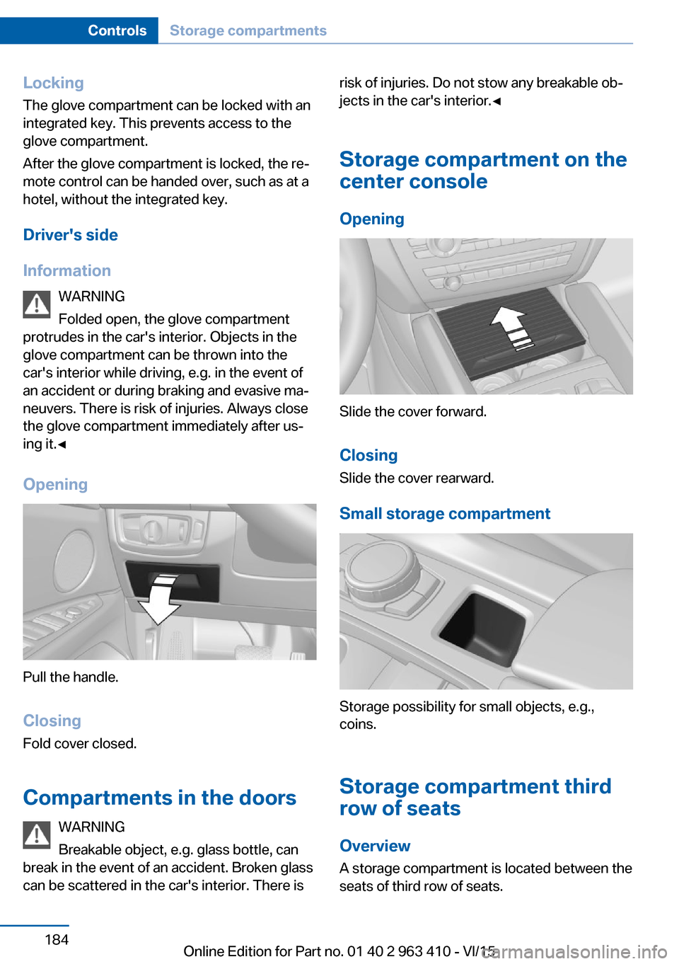
LockingThe glove compartment can be locked with an
integrated key. This prevents access to the
glove compartment.
After the glove compartment is locked, the re‐
mote control can be handed over, such as at a
hotel, without the integrated key.
Driver's side
Information WARNING
Folded open, the glove compartment
protrudes in the car's interior. Objects in the glove compartment can be thrown into the
car's interior while driving, e.g. in the event of
an accident or during braking and evasive ma‐
neuvers. There is risk of injuries. Always close
the glove compartment immediately after us‐ ing it.◀
Opening
Pull the handle.
ClosingFold cover closed.
Compartments in the doors WARNING
Breakable object, e.g. glass bottle, can
break in the event of an accident. Broken glass
can be scattered in the car's interior. There is
risk of injuries. Do not stow any breakable ob‐
jects in the car's interior.◀
Storage compartment on the
center console
Opening
Slide the cover forward.
Closing Slide the cover rearward.
Small storage compartment
Storage possibility for small objects, e.g.,
coins.
Storage compartment third
row of seats
Overview
A storage compartment is located between the
seats of third row of seats.
Seite 184ControlsStorage compartments184
Online Edition for Part no. 01 40 2 963 410 - VI/15
Page 185 of 275
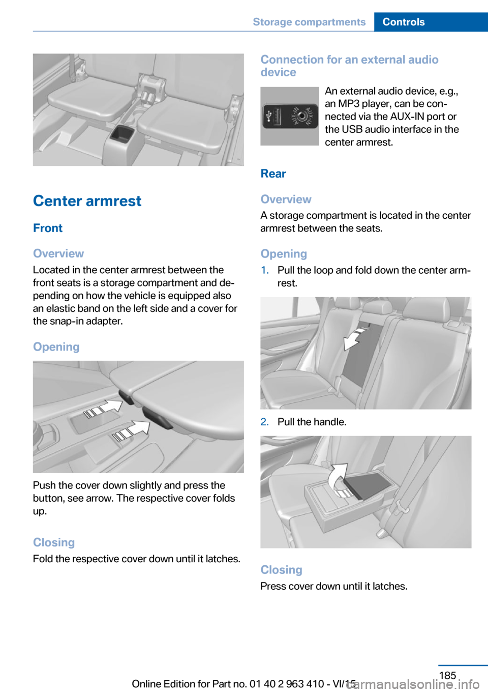
Center armrest
Front
Overview
Located in the center armrest between the
front seats is a storage compartment and de‐
pending on how the vehicle is equipped also
an elastic band on the left side and a cover for
the snap-in adapter.
Opening
Push the cover down slightly and press the
button, see arrow. The respective cover folds
up.
ClosingFold the respective cover down until it latches.
Connection for an external audio
device
An external audio device, e.g.,
an MP3 player, can be con‐
nected via the AUX-IN port or
the USB audio interface in the
center armrest.
Rear
Overview
A storage compartment is located in the center armrest between the seats.
Opening1.Pull the loop and fold down the center arm‐
rest.2.Pull the handle.
Closing
Press cover down until it latches.
Seite 185Storage compartmentsControls185
Online Edition for Part no. 01 40 2 963 410 - VI/15
Page 236 of 275
CoolantVehicle features and optionsThis chapter describes all standard, country-
specific and optional features offered with the
series. It also describes features that are not
necessarily available in your car, e. g., due to
the selected options or country versions. This
also applies to safety-related functions and
systems. The respectively applicable country
provisions must be observed when using the
respective features and systems.
Information WARNING
With the engine hot and the cooling sys‐
tem open, coolant can escape and lead to
burns. There is risk of injuries. Only open the
cooling system with the engine cooled down.◀
WARNING
Additives are harmful and incorrect addi‐
tives can damage the engine. There is risk of
injuries and risk of property damage. Avoid the
contact of articles of clothing, skin or eyes with
additives. Do not swallow any additives. Use
suitable additives only.◀
Coolant consists of water and additives.
Not all commercially available additives are
suitable for the vehicle. Information about suit‐
able additives is available from a dealer’s serv‐
ice center or another qualified service center or
repair shop.
Coolant level
General information
If there is no Min. and Max. mark in the filler
neck of the coolant reservoir, have the coolant
level checked if needed by your dealer’s serv‐ice center or another qualified service center or
repair shop and add coolant as needed.
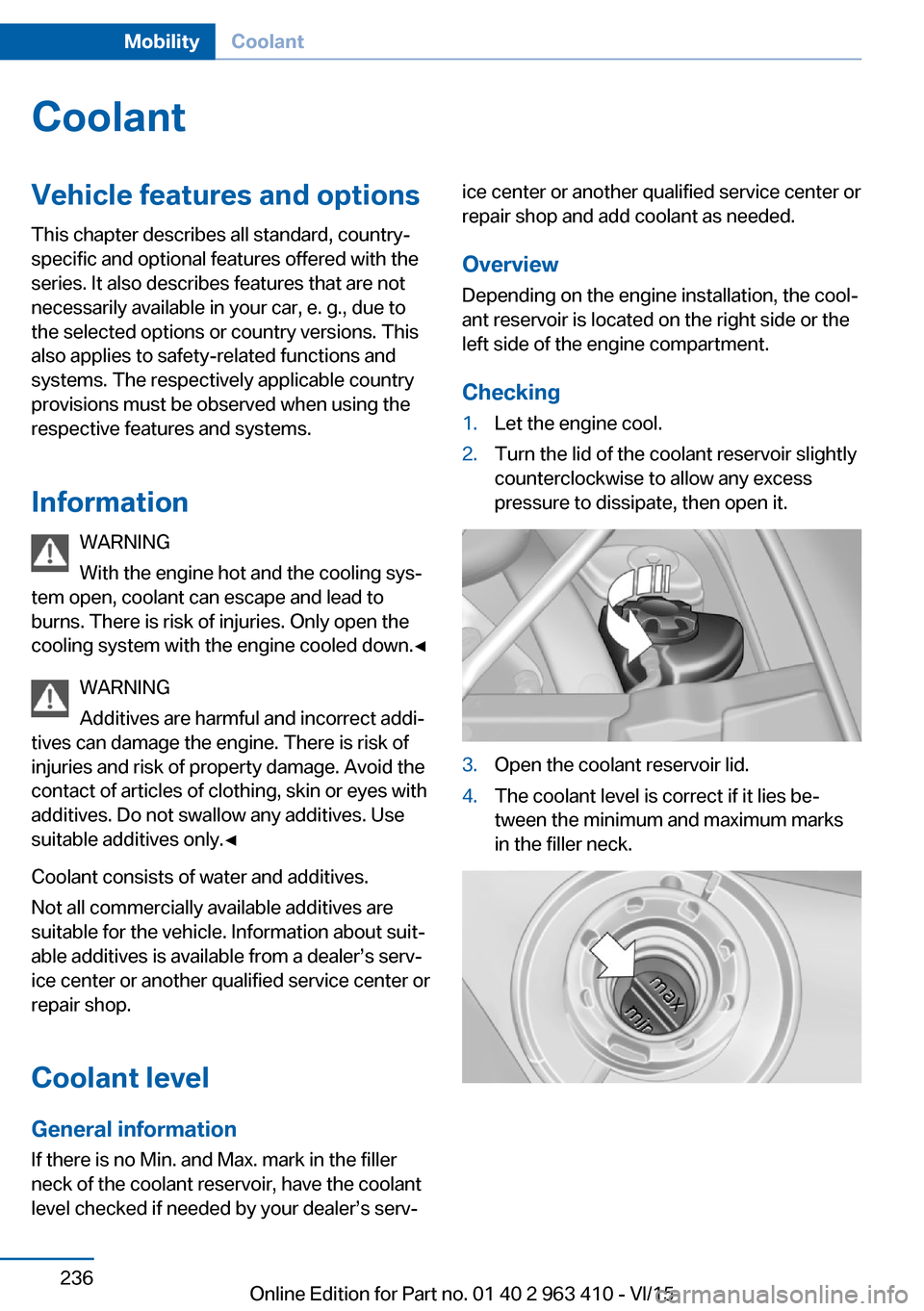
Overview
Depending on the engine installation, the cool‐
ant reservoir is located on the right side or the
left side of the engine compartment.
Checking1.Let the engine cool.2.Turn the lid of the coolant reservoir slightly
counterclockwise to allow any excess
pressure to dissipate, then open it.3.Open the coolant reservoir lid.4.The coolant level is correct if it lies be‐
tween the minimum and maximum marks
in the filler neck.Seite 236MobilityCoolant236
Online Edition for Part no. 01 40 2 963 410 - VI/15
Page 242 of 275
placement be performed by a dealer’s service
center or another qualified service center or re‐
pair shop.◀
Light-emitting diodes (LEDs)
Some items of equipment use light-emitting
diodes installed behind a cover as a light
source.
These light-emitting diodes, which are related
to conventional lasers, are officially designated
as Class 1 light-emitting diodes.
WARNING
Too intensive brightness can irritate or
damage the retina of the eye. There is risk of
injuries. Do not look directly into the headlights
or other light sources for an extended period of
time. Do not remove the LED covers.◀
Headlight glass
Condensation can form on the inside of the ex‐
ternal lights in cool or humid weather. When
driving with the lights switched on, the con‐
densation evaporates after a short time. The
headlight glass does not need to be changed.
If despite driving with the lights switched on,
increasing humidity forms, e. g. water droplets
in the lamp, the manufacturer of your vehicle
recommends having it checked by a dealer’s
service center or another qualified service cen‐
ter or repair shop.
Headlight setting The headlight adjustments can be affected by
changing lights and bulbs. After the headlight
adjustment was changed, have it checked and,
if necessary, corrected by a dealer’s service
center or another qualified service center or re‐
pair shop.Front lights, bulb replacement
Xenon headlights
Information
Because of the long service life of these bulbs,
the likelihood of failure is very low. Switching
the lights on and off frequently shortens their
service life.
If a bulb fails, turn on the front fog lights and
continue the trip with great care. Comply with local regulations.
DANGER
There can be high voltage in the lighting
system. There is danger to life. The manufac‐
turer of your vehicle recommends that the work on the lighting system including bulb re‐
placement be performed by a dealer’s service
center or another qualified service center or re‐
pair shop.◀
For checking and adjusting headlamp aim,
contact a dealer’s service center or another
qualified service center or repair shop.
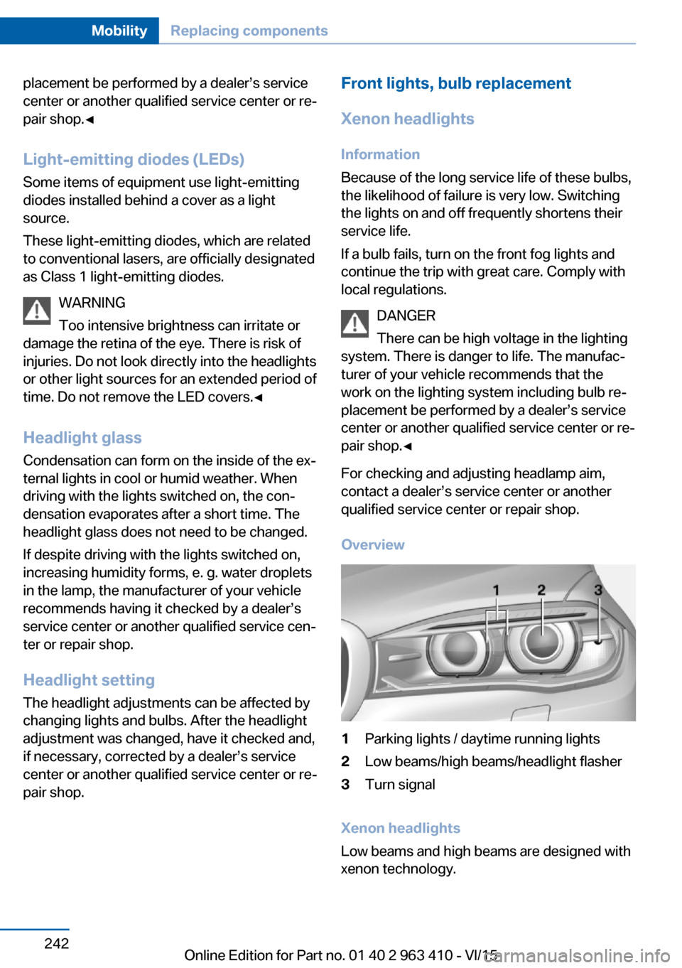
Overview1Parking lights / daytime running lights2Low beams/high beams/headlight flasher3Turn signal
Xenon headlights
Low beams and high beams are designed with
xenon technology.
Seite 242MobilityReplacing components242
Online Edition for Part no. 01 40 2 963 410 - VI/15
Page 245 of 275
InformationWARNING
The vehicle jack is optimized for lifting
the vehicle and for the jacking points on the
vehicle only. There is risk of injuries. Do not lift
any other vehicle or cargo using the vehicle
jack.◀
Overview
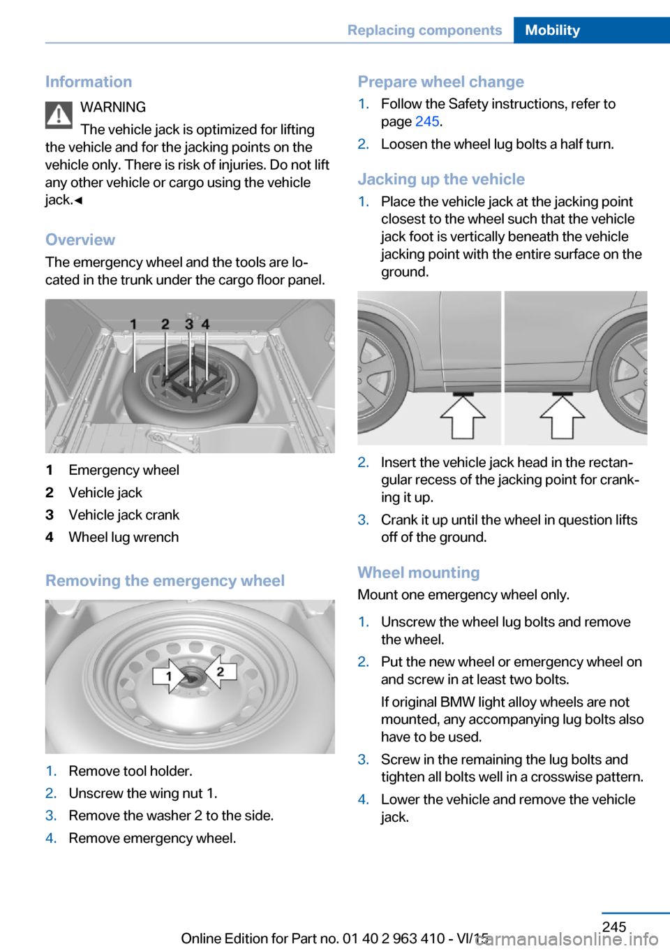
The emergency wheel and the tools are lo‐ cated in the trunk under the cargo floor panel.1Emergency wheel2Vehicle jack3Vehicle jack crank4Wheel lug wrench
Removing the emergency wheel
1.Remove tool holder.2.Unscrew the wing nut 1.3.Remove the washer 2 to the side.4.Remove emergency wheel.Prepare wheel change1.Follow the Safety instructions, refer to
page 245.2.Loosen the wheel lug bolts a half turn.
Jacking up the vehicle
1.Place the vehicle jack at the jacking point
closest to the wheel such that the vehicle
jack foot is vertically beneath the vehicle
jacking point with the entire surface on the
ground.2.Insert the vehicle jack head in the rectan‐
gular recess of the jacking point for crank‐
ing it up.3.Crank it up until the wheel in question lifts
off of the ground.
Wheel mounting
Mount one emergency wheel only.
1.Unscrew the wheel lug bolts and remove
the wheel.2.Put the new wheel or emergency wheel on
and screw in at least two bolts.
If original BMW light alloy wheels are not
mounted, any accompanying lug bolts also
have to be used.3.Screw in the remaining the lug bolts and
tighten all bolts well in a crosswise pattern.4.Lower the vehicle and remove the vehicle
jack.Seite 245Replacing componentsMobility245
Online Edition for Part no. 01 40 2 963 410 - VI/15
Page 265 of 275
Biodiesel 211
Blinds, sun protection 48
BMW Advanced Diesel 211
BMW Assist, see user's manual for Navigation, En‐
tertainment and Communi‐
cation
BMW Driver’s Guide App 6
BMW Homepage 6
BMW Internet page 6
BMW maintenance sys‐ tem 238
Bonus range, ECO PRO 201
Bottle holder, see Cu‐ pholder 186
Brake assistant 137
Brake assistant, adaptive 137
Brake discs, break-in 192
Brake force display 135
Brake lights, adaptive 135
Brake lights, brake force dis‐ play 135
Brake pads, break-in 192
Braking, hints 193
Breakdown assistance 248
Break-in 192
Brightness of Control Dis‐ play 101
Bulb replacement 241
Bulb replacement, front 242
Bulb replacement, rear 244
Bulbs and lights 241
Button, RES 148
Button, Start/Stop 69
Bypassing, see Jump-start‐ ing 249
C
California Proposition 65 Warning 8
Calling up mirror adjust‐ ment 45
Calling up seat adjust‐ ment 45 Calling up steering wheel ad‐
justment 45
Camera lenses, care 257
Camera, rearview cam‐ era 157
Camera, Side View 161
Camera, Top View 160
Can holder, see Cu‐ pholder 186
Car battery 246
Car care products 255
Care, displays 257
Care, vehicle 255
Cargo 196
Cargo area 181
Cargo area, enlarging 181
Cargo area, storage compart‐ ments 187
Cargo cover 181
Cargo, securing 197
Cargo straps, securing cargo 197
Car key, see Remote con‐ trol 34
Carpet, care 257
Car wash 254
Catalytic converter, see Hot exhaust system 193
CBS Condition Based Serv‐ ice 238
CD/Multimedia, see user's manual for Navigation, En‐
tertainment and Communi‐
cation
Center armrest 185
Center console 16
Central locking system 40
Central screen, see Control Display 18
Changes, technical, see Own Safety 7
Changing parts 240
Changing wheels 244
Changing wheels/tires 223
Chassis number, see vehicle identification number 10 Check Control 89
Checking the engine oil level electronically 232
Checking the oil level elec‐ tronically 232
Children, seating position 64
Children, transporting safely 64
Child restraint fixing sys‐ tem 64
Child restraint fixing system LATCH 66
Child restraint fixing systems, mounting 65
Child safety locks 68
Child seat, mounting 65
Child seats 64
Chrome parts, care 256
Cigarette lighter 177
Cleaning displays 257
Climate control 167
Climate control wind‐ shield 193
Clock 94
Closing/opening via door lock 39
Closing/opening with remote control 37
Clothes hooks 187
Coasting 203
Coasting with engine decou‐ pled, coasting 203
Coasting with idling en‐ gine 203
Cockpit 14
Cold starting, refer to Starting the engine 70
Combination switch, refer to Wiper system 77
Combination switch, see Turn signals 76
Comfort Access 43
COMFORT program, Driving Dynamics Control 143
Compact wheel, see Emer‐ gency wheel 244 Seite 265Everything from A to ZReference265
Online Edition for Part no. 01 40 2 963 410 - VI/15