Light switch BMW X5 2016 F15 Repair Manual
[x] Cancel search | Manufacturer: BMW, Model Year: 2016, Model line: X5, Model: BMW X5 2016 F15Pages: 275, PDF Size: 6.46 MB
Page 155 of 275
Switching on/off
Switching on automatically PDC switches on automatically in the following
situations:▷If selector lever position R is engaged
when the engine is running.
The rearview camera also switches on.▷If equipped with front PDC: when obsta‐
cles are detected behind or in front of the
vehicle by PDC and the speed is slower
than approx. 2.5 mph/4 km/h.
You may turn off automatic activation:
1."Settings"2."Parking"3.Select setting.
Settings are stored for the profile currently
used.
Automatic deactivation during forward
travel
The system switches off when a certain driving
distance or speed is exceeded.
Switch the system back on if needed.
With front PDC: switching on/off
manually
Press button.
▷On: the LED lights up.▷Off: the LED goes out.
The rearview camera image is displayed when
the reverse gear is engaged by pressing the
button.
Display
Signal tones When approaching an object, an intermittent
sound indicates the position of the object. E. g.
if an object is detected to the left rear of the
vehicle, a signal tone sounds from the left rear
speaker.
The shorter the distance to the object, the
shorter the intervals.
If the distance to a detected object is less than
approx. 10 in/25 cm, a continuous tone is
sounded.
With front PDC: if objects are located both in
front of and behind the vehicle, an alternating
continuous signal is sounded.
The signal tone is switched off, when selector
lever position P is engaged on vehicles with
Steptronic transmission.
Volume
The ratio of the PDC signal tone volume to the
entertainment volume can be adjusted.1."Multimedia", "Radio" or "Settings"2."Tone"3."Volume settings"4."PDC"5.Turn the controller until the desired setting
is selected.6.Press the controller.
Settings are stored for the profile currently
used.
Visual warning
The approach of the vehicle to an object can
be shown on the Control Display. Objects that
are farther away are already displayed on the
Control Display before a signal sounds.
A display appears as soon as Park Distance
Control (PDC) is activated.
The range of the sensors is represented in the
colors green, yellow and red.
When the image of the rearview camera is dis‐
played, the switch can be made to PDC:
"Rear view camera"
Seite 155Driving comfortControls155
Online Edition for Part no. 01 40 2 963 410 - VI/15
Page 157 of 275
tions. Watch traffic and vehicle surroundings
closely and actively interfere in the respective
situations.◀
Overview
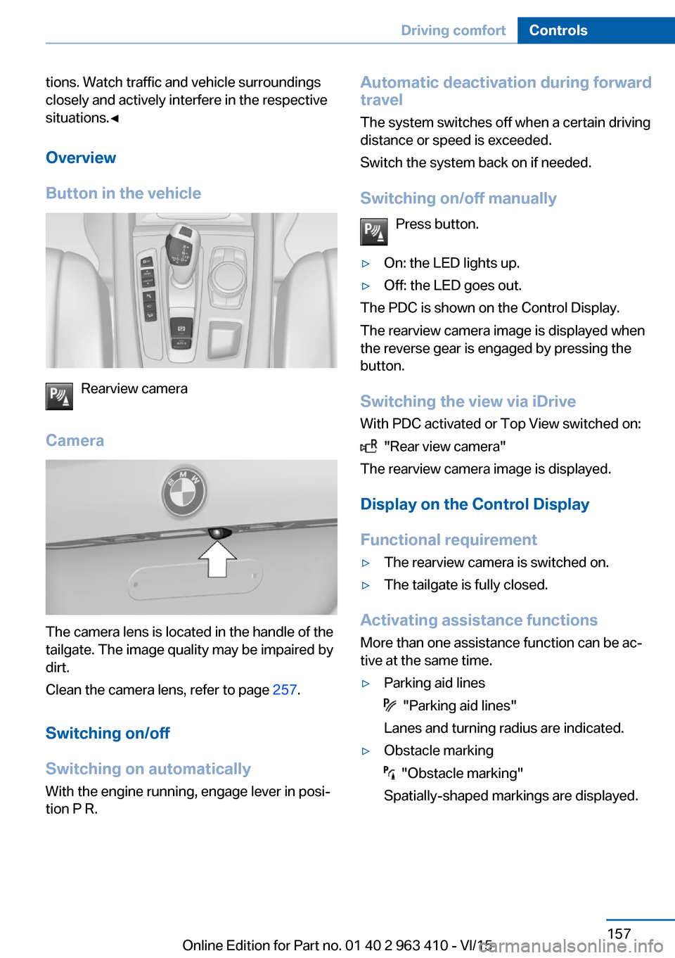
Button in the vehicle
Rearview camera
Camera
The camera lens is located in the handle of the
tailgate. The image quality may be impaired by
dirt.
Clean the camera lens, refer to page 257.
Switching on/off
Switching on automatically With the engine running, engage lever in posi‐
tion P R.
Automatic deactivation during forward
travel
The system switches off when a certain driving
distance or speed is exceeded.
Switch the system back on if needed.
Switching on/off manually Press button.▷On: the LED lights up.▷Off: the LED goes out.
The PDC is shown on the Control Display.
The rearview camera image is displayed when
the reverse gear is engaged by pressing the
button.
Switching the view via iDrive With PDC activated or Top View switched on:
"Rear view camera"
The rearview camera image is displayed.
Display on the Control Display
Functional requirement
▷The rearview camera is switched on.▷The tailgate is fully closed.
Activating assistance functions
More than one assistance function can be ac‐
tive at the same time.
▷Parking aid lines
"Parking aid lines"
Lanes and turning radius are indicated.
▷Obstacle marking
"Obstacle marking"
Spatially-shaped markings are displayed.
Seite 157Driving comfortControls157
Online Edition for Part no. 01 40 2 963 410 - VI/15
Page 160 of 275
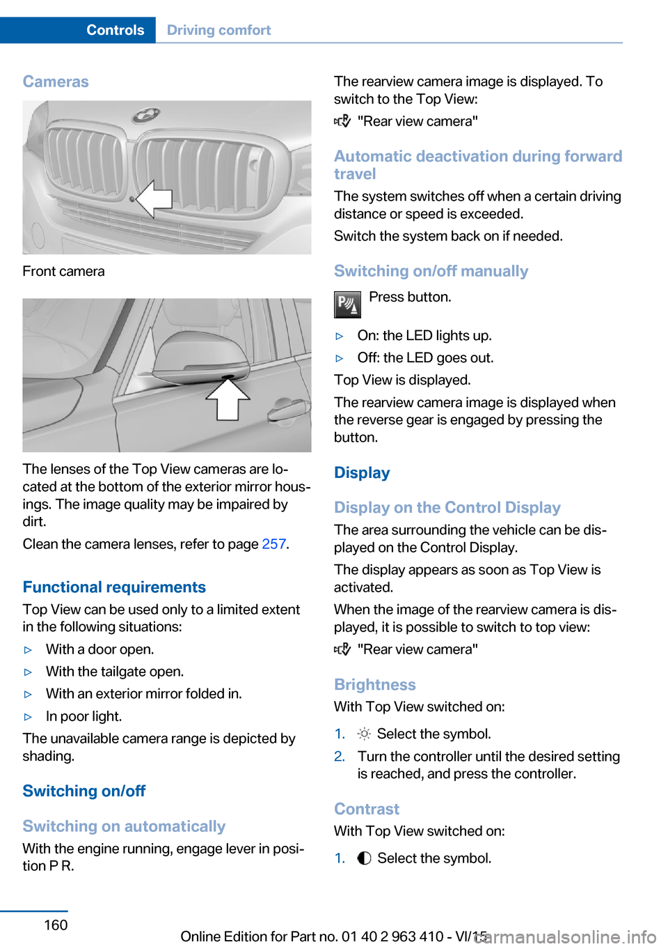
Cameras
Front camera
The lenses of the Top View cameras are lo‐
cated at the bottom of the exterior mirror hous‐
ings. The image quality may be impaired by
dirt.
Clean the camera lenses, refer to page 257.
Functional requirements
Top View can be used only to a limited extent
in the following situations:
▷With a door open.▷With the tailgate open.▷With an exterior mirror folded in.▷In poor light.
The unavailable camera range is depicted by
shading.
Switching on/off
Switching on automatically With the engine running, engage lever in posi‐
tion P R.
The rearview camera image is displayed. To
switch to the Top View:
"Rear view camera"
Automatic deactivation during forward
travel
The system switches off when a certain driving
distance or speed is exceeded.
Switch the system back on if needed.
Switching on/off manually Press button.
▷On: the LED lights up.▷Off: the LED goes out.
Top View is displayed.
The rearview camera image is displayed when
the reverse gear is engaged by pressing the
button.
Display
Display on the Control Display The area surrounding the vehicle can be dis‐
played on the Control Display.
The display appears as soon as Top View is
activated.
When the image of the rearview camera is dis‐
played, it is possible to switch to top view:
"Rear view camera"
Brightness
With Top View switched on:
1. Select the symbol.2.Turn the controller until the desired setting
is reached, and press the controller.
Contrast
With Top View switched on:
1. Select the symbol.Seite 160ControlsDriving comfort160
Online Edition for Part no. 01 40 2 963 410 - VI/15
Page 162 of 275
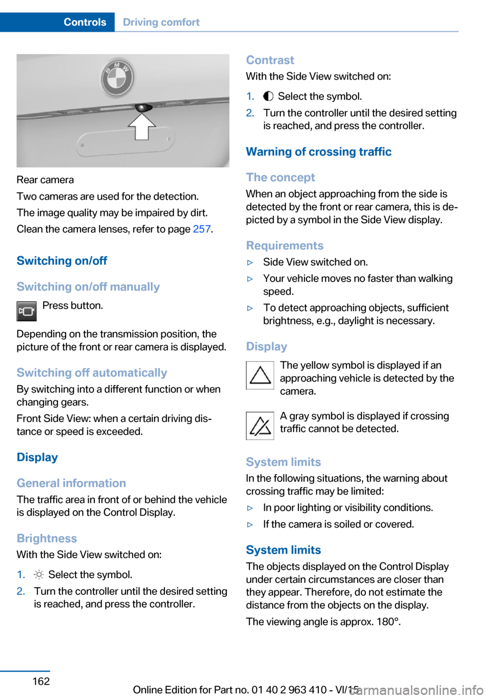
Rear camera
Two cameras are used for the detection.
The image quality may be impaired by dirt.
Clean the camera lenses, refer to page 257.
Switching on/off
Switching on/off manually Press button.
Depending on the transmission position, the
picture of the front or rear camera is displayed.
Switching off automatically By switching into a different function or when
changing gears.
Front Side View: when a certain driving dis‐
tance or speed is exceeded.
Display
General information
The traffic area in front of or behind the vehicle
is displayed on the Control Display.
Brightness With the Side View switched on:
1. Select the symbol.2.Turn the controller until the desired setting
is reached, and press the controller.Contrast
With the Side View switched on:1. Select the symbol.2.Turn the controller until the desired setting
is reached, and press the controller.
Warning of crossing traffic
The concept When an object approaching from the side is
detected by the front or rear camera, this is de‐
picted by a symbol in the Side View display.
Requirements
▷Side View switched on.▷Your vehicle moves no faster than walking
speed.▷To detect approaching objects, sufficient
brightness, e.g., daylight is necessary.
Display
The yellow symbol is displayed if anapproaching vehicle is detected by the
camera.
A gray symbol is displayed if crossing
traffic cannot be detected.
System limits
In the following situations, the warning about
crossing traffic may be limited:
▷In poor lighting or visibility conditions.▷If the camera is soiled or covered.
System limits
The objects displayed on the Control Display
under certain circumstances are closer than
they appear. Therefore, do not estimate the
distance from the objects on the display.
The viewing angle is approx. 180°.
Seite 162ControlsDriving comfort162
Online Edition for Part no. 01 40 2 963 410 - VI/15
Page 164 of 275
Requirements
For measuring parking spaces▷Maximum speed while driving forward ap‐
prox. 22 mph/35 km/h.▷Maximum distance to row of parked vehi‐
cles: 5 ft/1.5 m.
Suitable parking space
▷Gap between two objects with a minimum
length of approx. 5 ft/1.5 m.▷Min. length of gap between two objects:
your vehicle's length plus approx.
4 ft/1.2 m.▷Minimum depth: approx. 5 ft/1.5 m.
Regarding the parking procedure
▷Doors and tailgate closed.▷Parking brake released.▷Driver's safety belt fastened.
Switching on/off
Switching on with the button Press button.
The LED lights up.
The current status of the parking space search
is indicated on the Control Display.
Parking assistant is activated automatically.
Switching on with the reverse gear
Shift into reverse.
The current status of the parking space search
is indicated on the Control Display.
To activate:
"Parking Assistant"
Switch off
The system can be deactivated as follows:
▷Press button.Display on the Control Display
System activated/deactivatedSymbolMeaning Gray: the system is not available.
White: the system is available but
not activated. The system is activated.
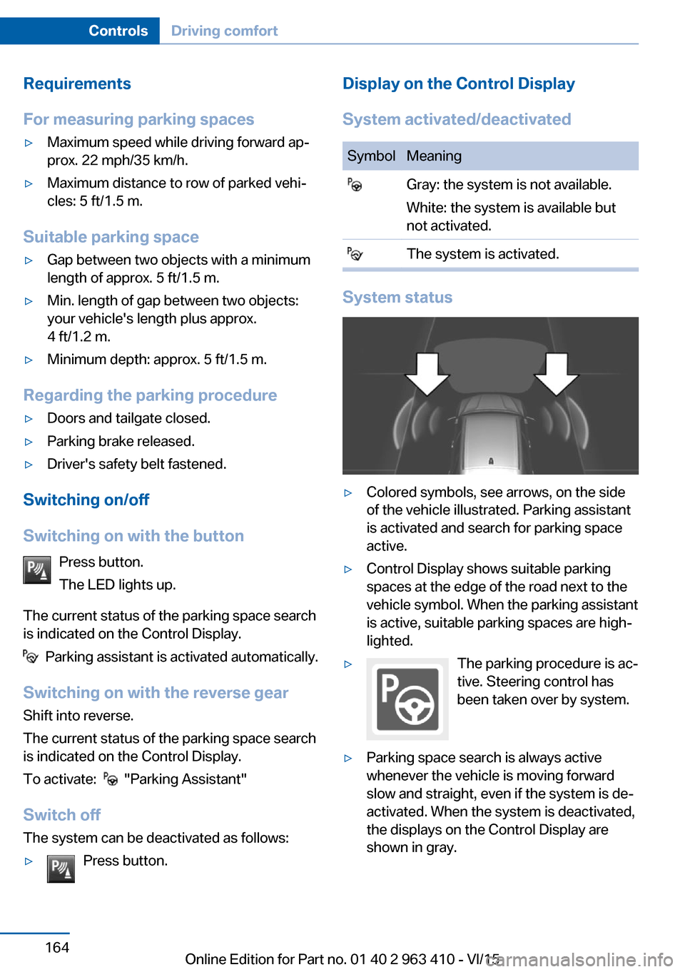
System status
▷Colored symbols, see arrows, on the side
of the vehicle illustrated. Parking assistant
is activated and search for parking space
active.▷Control Display shows suitable parking
spaces at the edge of the road next to the
vehicle symbol. When the parking assistant
is active, suitable parking spaces are high‐
lighted.▷The parking procedure is ac‐
tive. Steering control has
been taken over by system.▷Parking space search is always active
whenever the vehicle is moving forward
slow and straight, even if the system is de‐
activated. When the system is deactivated,
the displays on the Control Display are
shown in gray.Seite 164ControlsDriving comfort164
Online Edition for Part no. 01 40 2 963 410 - VI/15
Page 173 of 275
Manual air distribution
The air distribution can be adjusted to individ‐
ual needs.
Press button repeatedly to select a
program:▷Upper body region.▷Upper body region and footwell.▷Footwell.
Parked-car ventilation
The concept The parked-car ventilation ventilates the vehi‐
cle interior and lowers its temperature, if
needed.
The system can be switched on and off di‐
rectly or by using two preset departure times.
The reel-on time is automatically determined
based on the temperature. The system
promptly switches on before the selected de‐
parture time.
Operation can be performed via iDrive.
Functional requirements
Parked-car ventilation
▷When the departure time is preselected:
depends on internal, external and set tem‐
perature.▷Direct operation: any external temperature.
Open the vents to allow air to flow out.
Switching on/off directly
On the Control Display:
1."Settings"2."Climate"3."Activate now"
The symbol on the automatic climate con‐
trol flashes if the system is switched on.
The system continues to run for some time af‐
ter being switched off.
Setting departure time
On the Control Display:1."Settings"2."Climate"3.Select the departure time.
Turn the controller until the desired depar‐
ture time field has been selected and press
Controller.4.Set the time.
Turn the controller until the desired time is
set and press the controller.
Activating the departure time
On the Control Display:
1."Settings"2."Climate"3.Activating the desired departure time:
"for departure at"
The symbol on the automatic climate con‐
trol lights up when the departure time is acti‐
vated.
The symbol on the automatic climate con‐
trol flashes when the system has been
switched on.
The system will only be switched on within the
next 24 hours. After that, it needs to be reacti‐
vated.
Seite 173Climate controlControls173
Online Edition for Part no. 01 40 2 963 410 - VI/15
Page 174 of 275
Interior equipmentVehicle features and optionsThis chapter describes all standard, country-
specific and optional features offered with the
series. It also describes features that are not
necessarily available in your car, e. g., due to
the selected options or country versions. This
also applies to safety-related functions and
systems. The respectively applicable country
provisions must be observed when using the
respective features and systems.
Universal Integrated Remote Control
The concept The universal garage door opener can operate
up to 3 functions of remote-controlled sys‐
tems such as garage door drives or lighting
systems. The universal garage door opener re‐
places up to 3 different hand-held transmitters.
To operate the remote control, the buttons on
the interior rearview mirror must be program‐
med with the desired functions. The hand-held
transmitter for the particular system is required
in order to program the remote control.
Before selling the vehicle, delete the stored
functions for the sake of security.
Information WARNING
Body parts can be jammed when operat‐
ing remote-controlled systems, e.g. the garage
door, using the universal garage door opener.
There is risk of injuries or risk of property dam‐
age. Make sure that the area of movement of
the respective system is clear during program‐
ming and operation. Also follow the safety in‐
structions of the hand-held transmitter.◀Compatibility
If this symbol is printed on the packag‐
ing or in the instructions of the system
to be controlled, the system is gener‐
ally compatible with the universal garage door opener.
If you have any questions, please contact:▷A dealer’s service center or another quali‐
fied service center or repair shop.▷www.homelink.com on the Internet.
HomeLink is a registered trademark of Gentex
Corporation.
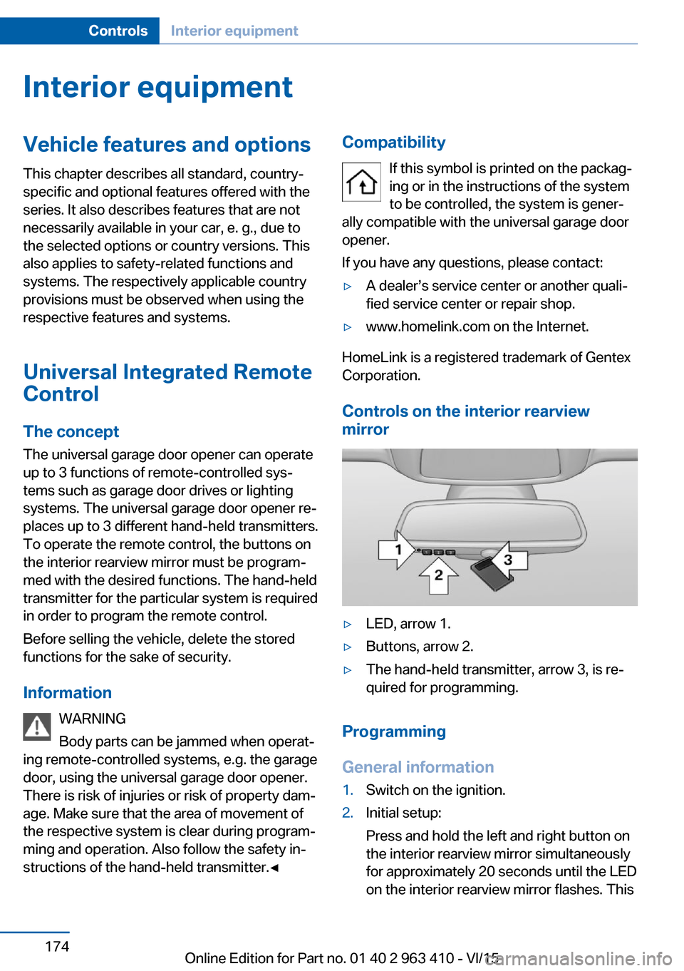
Controls on the interior rearview
mirror
▷LED, arrow 1.▷Buttons, arrow 2.▷The hand-held transmitter, arrow 3, is re‐
quired for programming.
Programming
General information
1.Switch on the ignition.2.Initial setup:
Press and hold the left and right button on
the interior rearview mirror simultaneously
for approximately 20 seconds until the LED
on the interior rearview mirror flashes. ThisSeite 174ControlsInterior equipment174
Online Edition for Part no. 01 40 2 963 410 - VI/15
Page 176 of 275
4.Likewise, press and hold the button of the
desired function on the hand-held trans‐
mitter.5.Release both buttons as soon as the inte‐
rior rearview mirror LED flashes more rap‐
idly. The LED flashing faster indicates that
the button on the interior rearview mirror
has been programmed. The system can
then be controlled by the button on the in‐
terior rearview mirror.
If the LED does not flash faster after at
least 60 seconds, change the distance and
repeat the step. Several more attempts at
different distances may be necessary. Wait
at least 15 seconds between attempts.
Canada: if programming with the hand-
held transmitter was interrupted, hold
down the interior rearview mirror button
and repeatedly press and release the
hand-held transmitter button for 2 sec‐
onds.
Controls
WARNING
Body parts can be jammed when operat‐
ing remote-controlled systems, e.g. the garage
door, using the universal garage door opener. There is risk of injuries or risk of property dam‐
age. Make sure that the area of movement of
the respective system is clear during program‐
ming and operation. Also follow the safety in‐
structions of the hand-held transmitter.◀
The system, such as the garage door, can be
operated using the button on the interior rear‐
view mirror while the engine is running or when
the ignition is started. To do this, hold down
the button within receiving range of the system
until the function is activated. The interior rear‐
view mirror LED stays lit while the wireless sig‐
nal is being transmitted.
Deleting stored functions Press and hold the left and right button on the
interior rearview mirror simultaneously for ap‐
proximately 20 seconds until the LED flashes
rapidly. All stored functions are deleted. The
functions cannot be deleted individually.
Sun visor Glare shieldFold the sun visor down or up.
Glare shield from the side
Folding out1.Fold the sun visor down.2.Unhook it from the holder and swing it to
the side.3.Move it back to the desired position.
Folding up
Proceed in the reverse order to close the sun
visor.
Vanity mirror A vanity mirror is located in the sun visor be‐
hind a cover. When the cover is opened, the
mirror lighting switches on.
Ashtray
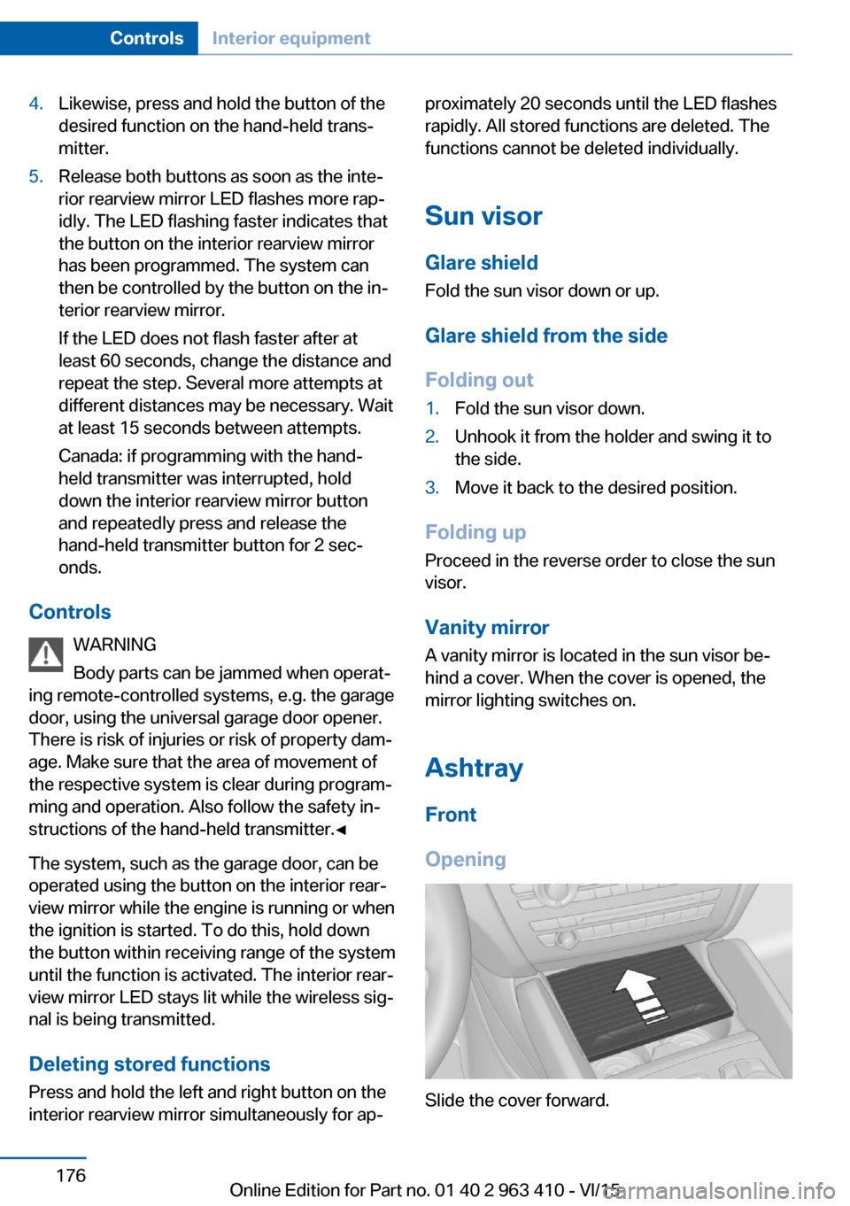
Front
Opening
Slide the cover forward.
Seite 176ControlsInterior equipment176
Online Edition for Part no. 01 40 2 963 410 - VI/15
Page 178 of 275
Connecting electrical
devices
Information CAUTION
Battery chargers for the vehicle battery
can work with high voltages and currents,
which means that the 12V on-board network
can be overloaded or damaged. There is risk of
property damage. Only connect battery charg‐
ers for the vehicle battery to the starting aid
terminals in the engine compartment.◀
CAUTION
If metal objects fall into the socket, they
can cause a short circuit. There is risk of prop‐
erty damage. Replace the cigarette lighter or socket cover again after using the socket.◀
Sockets
General information The lighter socket can be used as a socket for
electrical equipment while the engine is run‐
ning or when the ignition is switched on.
Information The total load of all sockets must not exceed
140 watts at 12 volts.
Do not damage the socket by using non-com‐
patible connectors.
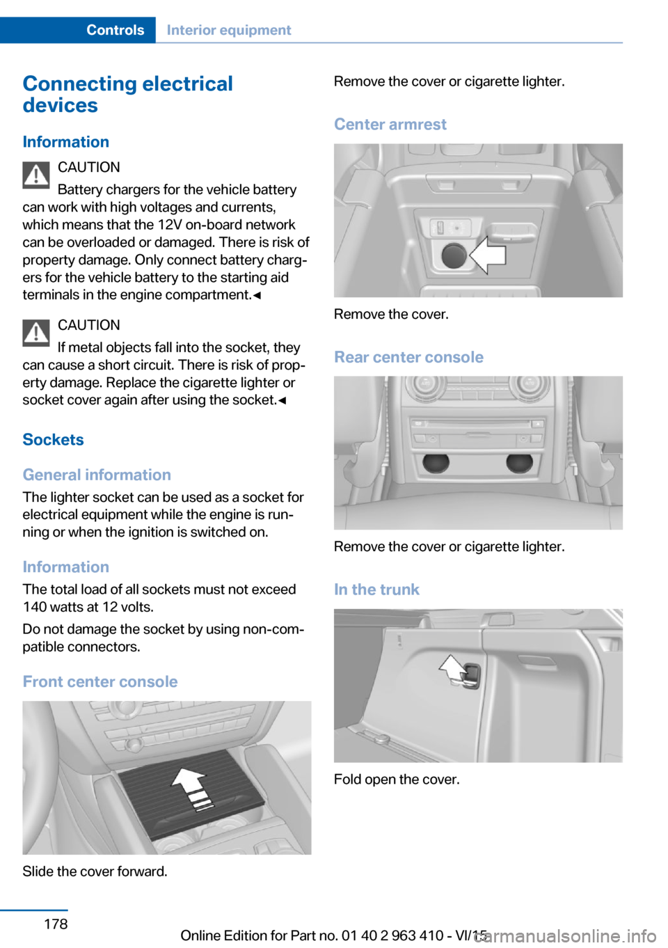
Front center console
Slide the cover forward.
Remove the cover or cigarette lighter.
Center armrest
Remove the cover.
Rear center console
Remove the cover or cigarette lighter.
In the trunk
Fold open the cover.
Seite 178ControlsInterior equipment178
Online Edition for Part no. 01 40 2 963 410 - VI/15
Page 179 of 275
USB interface for data
transfer
The concept Connection for importing and exporting data
on USB devices, e.g.:▷Personal Profile settings, refer to page 35.▷Music collection, see user's manual for
Navigation, Entertainment and Communi‐
cation.
Information
Observe the following when connecting:
▷Do not use force when plugging the con‐
nector into the USB interface.▷Do not connect devices such as fans or
lights to the USB interface.▷Do not connect USB hard drives.▷Do not use the USB interface for recharg‐
ing external devices.
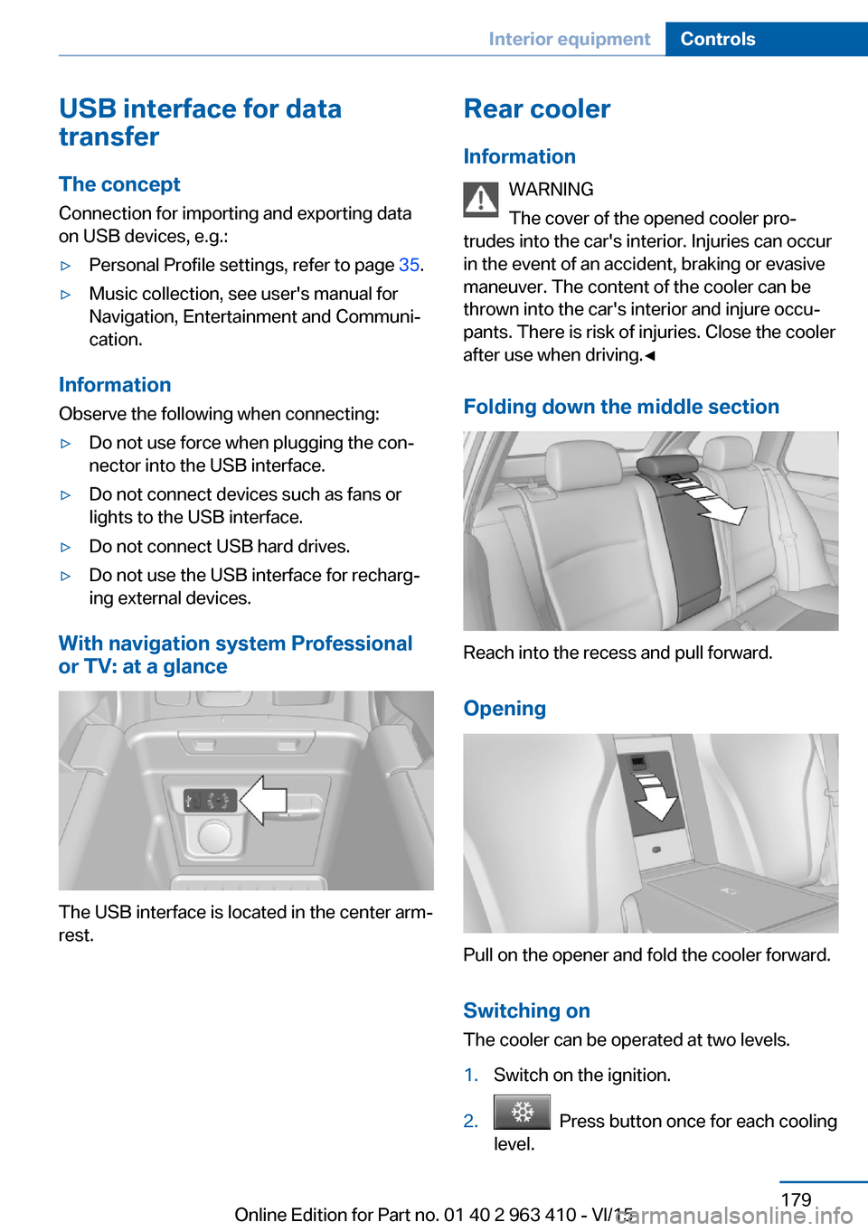
With navigation system Professional
or TV: at a glance
The USB interface is located in the center arm‐
rest.
Rear cooler
Information WARNING
The cover of the opened cooler pro‐
trudes into the car's interior. Injuries can occur
in the event of an accident, braking or evasive
maneuver. The content of the cooler can be
thrown into the car's interior and injure occu‐
pants. There is risk of injuries. Close the cooler
after use when driving.◀
Folding down the middle section
Reach into the recess and pull forward.
Opening
Pull on the opener and fold the cooler forward. Switching onThe cooler can be operated at two levels.
1.Switch on the ignition.2. Press button once for each cooling
level.
Seite 179Interior equipmentControls179
Online Edition for Part no. 01 40 2 963 410 - VI/15