BMW X5 3.0I 2001 Service Manual
Manufacturer: BMW, Model Year: 2001, Model line: X5 3.0I, Model: BMW X5 3.0I 2001Pages: 223, PDF Size: 2.66 MB
Page 41 of 223
Index
Data
Technology
Repairs
Car care
Controls
Overview
41nLiftgate Tailgate
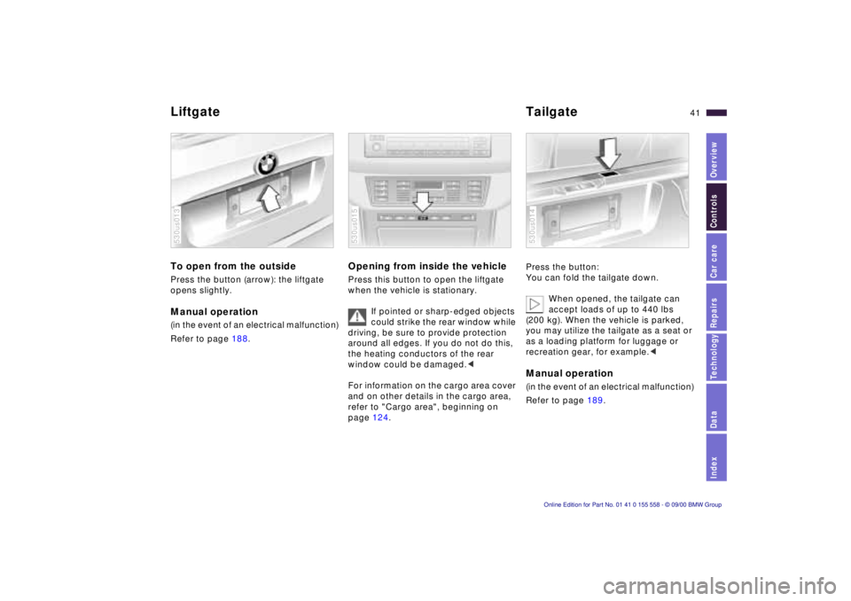
To open from the outside
Press the button (arrow): the liftgate
opens slightly.
Manual operation
(in the event of an electrical malfunction)
Refer to page 188.
530us013
Opening from inside the vehicle
Press this button to open the liftgate
when the vehicle is stationary.
If pointed or sharp-edged objects
could strike the rear window while
driving, be sure to provide protection
around all edges. If you do not do this,
the heating conductors of the rear
window could be damaged. <
For information on the cargo area cover
and on other details in the cargo area,
refer to "Cargo area", beginning on
page 124.
530us015
Press the button:
You can fold the tailgate down.
When opened, the tailgate can
accept loads of up to 440 lbs
(200 kg). When the vehicle is parked,
you may utilize the tailgate as a seat or
as a loading platform for luggage or
recreation gear, for example. <
Manual operation
(in the event of an electrical malfunction)
Refer to page 189.
530us014
Page 42 of 223
42nLiftgate
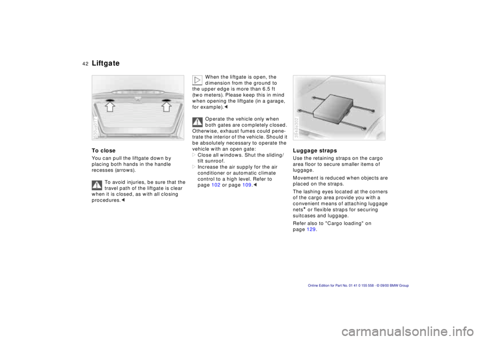
To close
You can pull the liftgate down by
placing both hands in the handle
recesses (arrows).
To avoid injuries, be sure that the
travel path of the liftgate is clear
when it is closed, as with all closing
procedures. <
530us017
When the liftgate is open, the
dimension from the ground to
the upper edge is more than 6.5 ft
(two meters). Please keep this in mind
when opening the liftgate (in a garage,
for example). <
Operate the vehicle only when
both gates are completely closed.
Otherwise, exhaust fumes could pene-
trate the interior of the vehicle. Should it
be absolutely necessary to operate the
vehicle with an open gate:
> Close all windows. Shut the sliding/
tilt sunroof.
> Increase the air supply for the air
conditioner or automatic climate
control to a high level. Refer to
page 102 or page 109.<
Luggage straps
Use the retaining straps on the cargo
area floor to secure smaller items of
luggage.
Movement is reduced when objects are
placed on the straps.
The lashing eyes located at the corners
of the cargo area provide you with a
convenient means of attaching luggage
nets
* or flexible straps for securing
suitcases and luggage.
Refer also to "Cargo loading" on
page 129.
394de302
Page 43 of 223
Index
Data
Technology
Repairs
Car care
Controls
Overview
43nAlarm system
The concept
The vehicle alarm system responds:
>When a door, the hood, or the liftgate
is opened.
> To movement inside the vehicle (inte-
rior motion sensor).
> To variations in the vehicle tilt sensor
such as occur during attempts to
steal the wheels or tow the vehicle.
> To interruption of battery voltage.
The system responds to unauthorized
vehicle entry and attempted theft by
simultaneously activating the following:
> Sounding an acoustical alarm for
30 seconds.
> The hazard warning flashers are acti-
vated for approx. five minutes.
> The high beams flash on and off in
the same rhythm.
To activate and deactivate the
alarm system
When the vehicle is locked or unlocked
with the key or the remote control, the
alarm system is also simultaneously
armed or disarmed.
The interior motion sensor is activated
approx. 30 seconds after you have
finished locking the vehicle.
The system indicates that it has been
correctly armed by switching on the
hazard flashers for a single cycle and by
emitting an acoustical signal.
You can have different acknowl-
edgment signals set to confirm
system arming and disarming. <
You can still open the liftgate after the
system has been armed by pressing
button 3 of the remote control. Refer to
page 39. When you close the liftgate, it
is secured again.
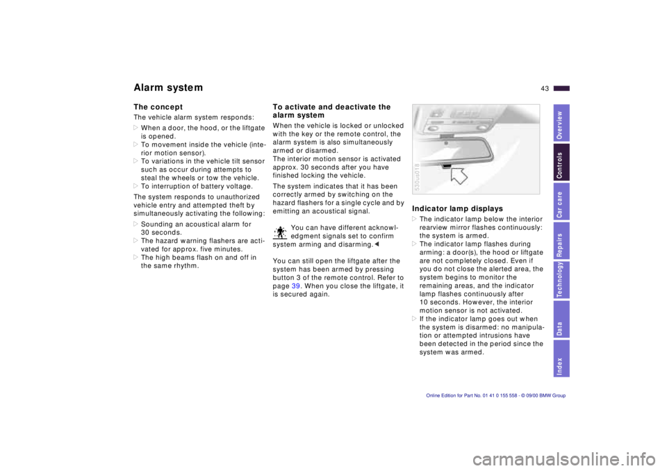
Indicator lamp displays
> The indicator lamp below the interior
rearview mirror flashes continuously:
the system is armed.
> The indicator lamp flashes during
arming: a door(s), the hood or liftgate
are not completely closed. Even if
you do not close the alerted area, the
system begins to monitor the
remaining areas, and the indicator
lamp flashes continuously after
10 seconds. However, the interior
motion sensor is not activated.
> If the indicator lamp goes out when
the system is disarmed: no manipula-
tion or attempted intrusions have
been detected in the period since the
system was armed.
530us018
Page 44 of 223
44nAlarm system
>If the indicator lamp flashes for
10 seconds when the system is
disarmed: an attempted entry has
been detected in the period since the
system was armed.
Following triggering of an alarm, the
indicator lamp will flash continuously.
Avoiding unintentional alarms
The tilt alarm sensor and interior motion
sensor may be switched off at the same
time. To prevent a false alarm from
being triggered (in garages with
elevator ramps, for instance), or when
the vehicle is transported by trailer or
train:
Actuate the lock (= arm the system)
twice; in other words, press button 2 of
the remote control twice in succession
(refer to page 38). You may also actuate
the locks twice with the key (refer to
page 36).
The indicator lamp lights up briefly and
then flashes continuously. The tilt alarm
sensor and the interior motion sensor
are deactivated as long as the system is
armed.
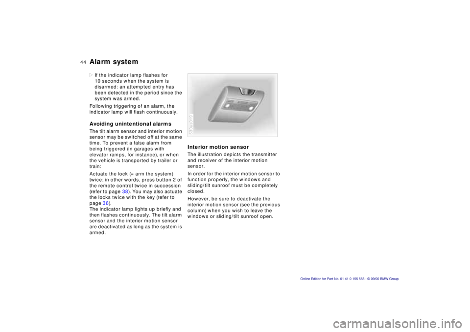
Interior motion sensor
The illustration depicts the transmitter
and receiver of the interior motion
sensor.
In order for the interior motion sensor to
function properly, the windows and
sliding/tilt sunroof must be completely
closed.
However, be sure to deactivate the
interior motion sensor (see the previous
column) when you wish to leave the
windows or sliding/tilt sunroof open.
530us019
Page 45 of 223
Index
Data
Technology
Repairs
Car care
Controls
Overview
45nElectric power windows
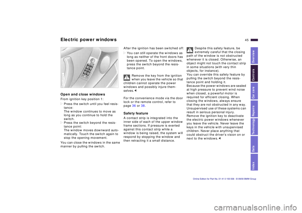
Open and close windows
From ignition key position 1:
>Press the switch until you feel resis-
tance:
The window continues to move as
long as you continue to hold the
switch.
> Press the switch beyond the resis-
tance point:
The window moves downward auto-
matically. Touch the switch again to
stop the opening movement.
You can close the windows in the same
manner by pulling the switch.
530us020
After the ignition has been switched off:
> You can still operate the windows as
long as neither of the front doors has
been opened. To open the windows,
press the switch beyond the resis-
tance point.
Remove the key from the ignition
when you leave the vehicle so that
children cannot operate the power
windows and possibly injure them-
selves. <
For the convenience mode via the door
lock or the remote control, refer to
page 36 or 38.
Safety feature
A contact strip is integrated into the
inner side of each of the upper window
frame sections. If pressure is exerted
against this contact strip while a
window is being raised, the system will
respond by stopping the window and
then retracting it a small distance.
Despite this safety feature, be
extremely careful that the closing
path of the window is not obstructed
whenever it is closed. Otherwise, an
object might not touch the contact strip
in some situations (with very thin
objects, for instance).
You can override this safety feature by
pulling the switch beyond the resis-
tance point and holding it.
Because the power windows are sealed
at high pressure to prevent wind noise
when closed, a powerful motor is
required for efficient closing. When
closing the windows, always ensure
that they are not obstructed in any way.
Unsupervised use of these systems can
result in serious personal injury.
Remove the ignition key to deactivate
the electric power windows whenever
you leave the vehicle. Never leave the
keys in the vehicle with unsupervised
children. Never place anything that
could obstruct the driver's vision on or
next to the windows. <
Page 46 of 223
46nElectric power windows Sliding/Tilt sunroof with glass moonroof*
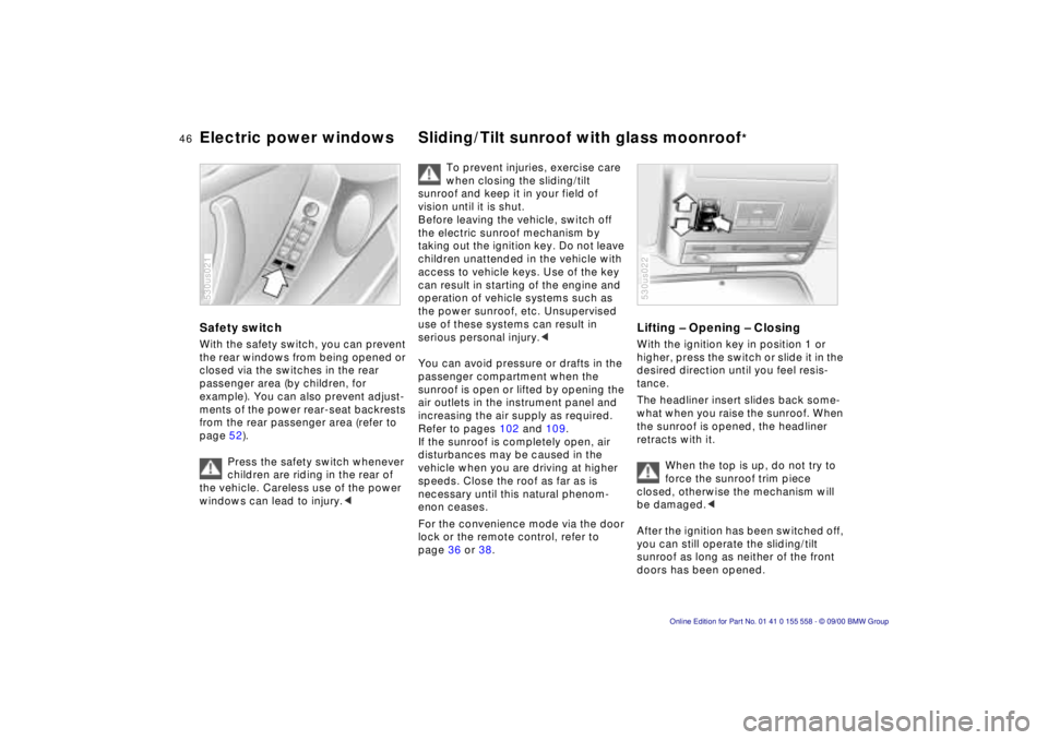
Safety switch
With the safety switch, you can prevent
the rear windows from being opened or
closed via the switches in the rear
passenger area (by children, for
example). You can also prevent adjust-
ments of the power rear-seat backrests
from the rear passenger area (refer to
page 52).
Press the safety switch whenever
children are riding in the rear of
the vehicle. Careless use of the power
windows can lead to injury. <
530us021
To prevent injuries, exercise care
when closing the sliding/tilt
sunroof and keep it in your field of
vision until it is shut.
Before leaving the vehicle, switch off
the electric sunroof mechanism by
taking out the ignition key. Do not leave
children unattended in the vehicle with
access to vehicle keys. Use of the key
can result in starting of the engine and
operation of vehicle systems such as
the power sunroof, etc. Unsupervised
use of these systems can result in
serious personal injury. <
You can avoid pressure or drafts in the
passenger compartment when the
sunroof is open or lifted by opening the
air outlets in the instrument panel and
increasing the air supply as required.
Refer to pages 102 and 109.
If the sunroof is completely open, air
disturbances may be caused in the
vehicle when you are driving at higher
speeds. Close the roof as far as is
necessary until this natural phenom-
enon ceases.
For the convenience mode via the door
lock or the remote control, refer to
page 36 or 38.
Lifting – Opening – Closing
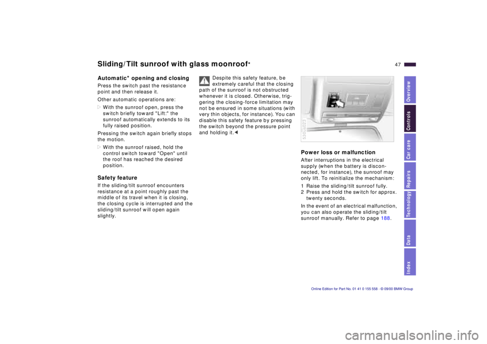
With the ignition key in position 1 or
higher, press the switch or slide it in the
desired direction until you feel resis-
tance.
The headliner insert slides back some-
what when you raise the sunroof. When
the sunroof is opened, the headliner
retracts with it.
When the top is up, do not try to
force the sunroof trim piece
closed, otherwise the mechanism will
be damaged. <
After the ignition has been switched off,
you can still operate the sliding/tilt
sunroof as long as neither of the front
doors has been opened.
530us022
Page 47 of 223
Index
Data
Technology
Repairs
Car care
Controls
Overview
47nSliding/Tilt sunroof with glass moonroof*
Automatic* opening and closing
Press the switch past the resistance
point and then release it.
Other automatic operations are:
>With the sunroof open, press the
switch briefly toward "Lift:" the
sunroof automatically extends to its
fully raised position.
Pressing the switch again briefly stops
the motion.
> With the sunroof raised, hold the
control switch toward "Open" until
the roof has reached the desired
position.
Safety feature
If the sliding/tilt sunroof encounters
resistance at a point roughly past the
middle of its travel when it is closing,
the closing cycle is interrupted and the
sliding/tilt sunroof will open again
slightly. Despite this safety feature, be
extremely careful that the closing
path of the sunroof is not obstructed
whenever it is closed. Otherwise, trig-
gering the closing-force limitation may
not be ensured in some situations (with
very thin objects, for instance). You can
disable this safety feature by pressing
the switch beyond the pressure point
and holding it. <
Power loss or malfunction
After interruptions in the electrical
supply (when the battery is discon-
nected, for instance), the sunroof may
only lift. To reinitialize the mechanism:
1 Raise the sliding/tilt sunroof fully.
2 Press and hold the switch for approx.
twenty seconds.
In the event of an electrical malfunction,
you can also operate the sliding/tilt
sunroof manually. Refer to page 188.
530us023
Page 48 of 223
48n
For maximum safety when adjusting the
seat position, please observe the
following: Never try to adjust your seat while
driving the vehicle. The seat could
respond with unexpected movement,
and the ensuing loss of vehicle control
could lead to an accident.
Be sure that the safety belt remains
firmly against your body at all times. In
the event of a frontal impact, a loose lap
belt could slide over your hips, leading
to abdominal injury. In addition, the
safety belt's restraint effectiveness is
reduced if the belt is worn loosely.
Never ride with the backrest reclined to
an extreme angle (especially important
for the front passenger to remember).
If you do so, there is a risk that you will
slide under the safety belt in an acci-
dent, thus reducing the protection
provided by the safety belt. <
Correct sitting posture
To reduce strain on the spinal column,
sit all the way back in the seat and rest
your back fully against the backrest.
The ideal sitting posture is achieved
with your head extending from your
spine in a straight line.
For long-distance driving, you may
wish to angle the backrest slightly to
reduce muscular tension. You should
be able to reach the highest point on
the steering wheel without straight-
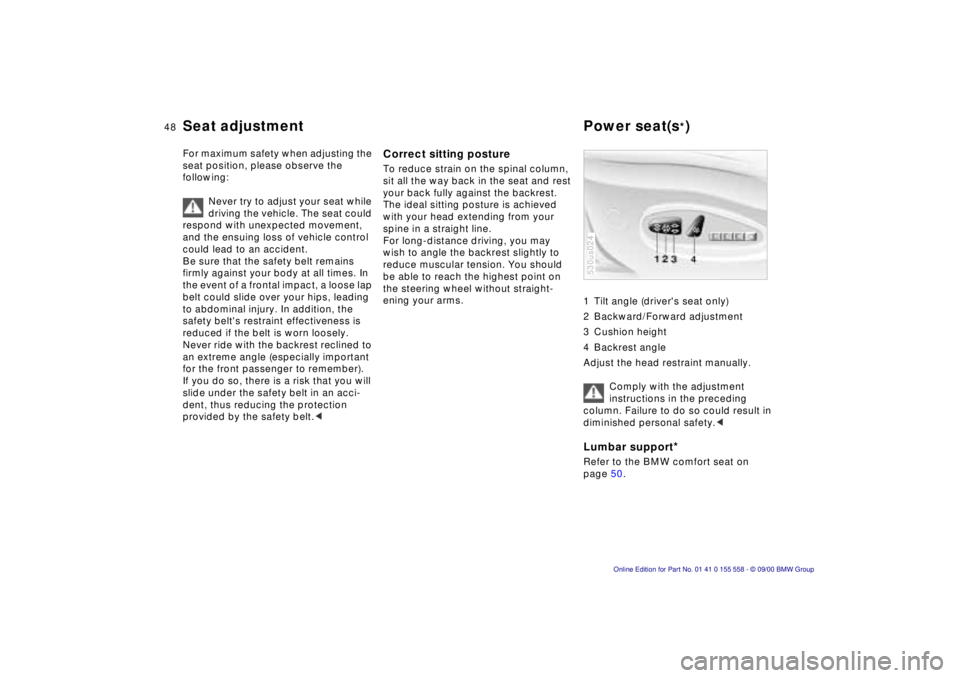
ening your arms. 1 Tilt angle (driver's seat only)
2 Backward/Forward adjustment
3 Cushion height
4 Backrest angle
Adjust the head restraint manually.
Comply with the adjustment
instructions in the preceding
column. Failure to do so could result in
diminished personal safety. <
Lumbar support*
Refer to the BMW comfort seat on
page 50.
530us024
Seat adjustment Power seat(s*)
Page 49 of 223
Index
Data
Technology
Repairs
Car care
Controls
Overview
49nMechanical seat Head restraints
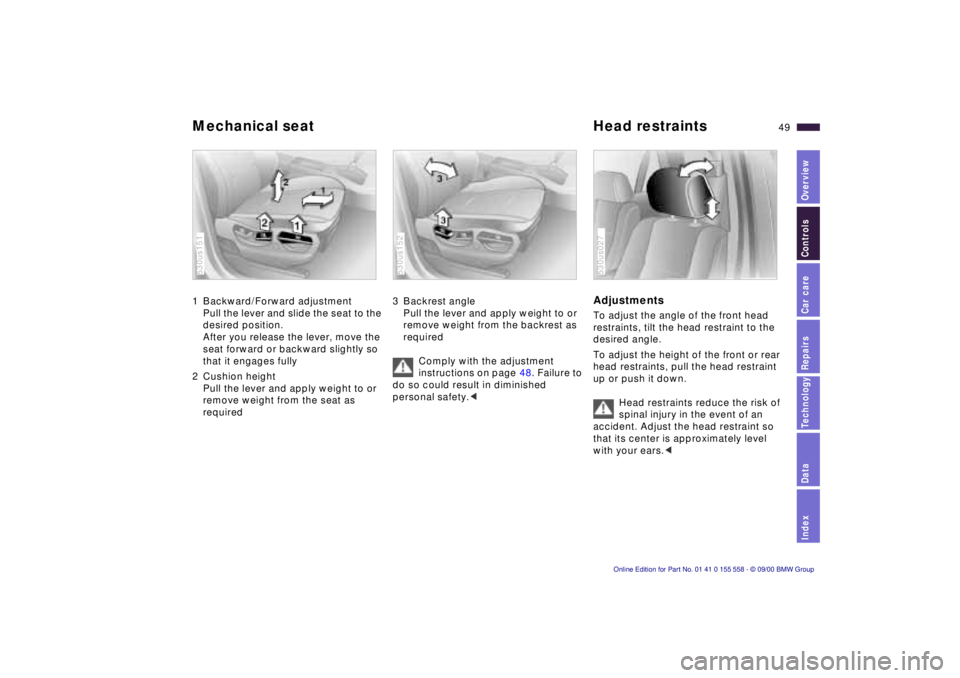
1 Backward/Forward adjustment
Pull the lever and slide the seat to the
desired position.
After you release the lever, move the
seat forward or backward slightly so
that it engages fully
2 Cushion height Pull the lever and apply weight to or
remove weight from the seat as
required
530us151
3 Backrest anglePull the lever and apply weight to or
remove weight from the backrest as
required
Comply with the adjustment
instructions on page 48. Failure to
do so could result in diminished
personal safety. <
530us152
Adjustments
To adjust the angle of the front head
restraints, tilt the head restraint to the
desired angle.
To adjust the height of the front or rear
head restraints, pull the head restraint
up or push it down.
Head restraints reduce the risk of
spinal injury in the event of an
accident. Adjust the head restraint so
that its center is approximately level
with your ears. <
530us027
Page 50 of 223
50nHead restraints BMW comfort seat*
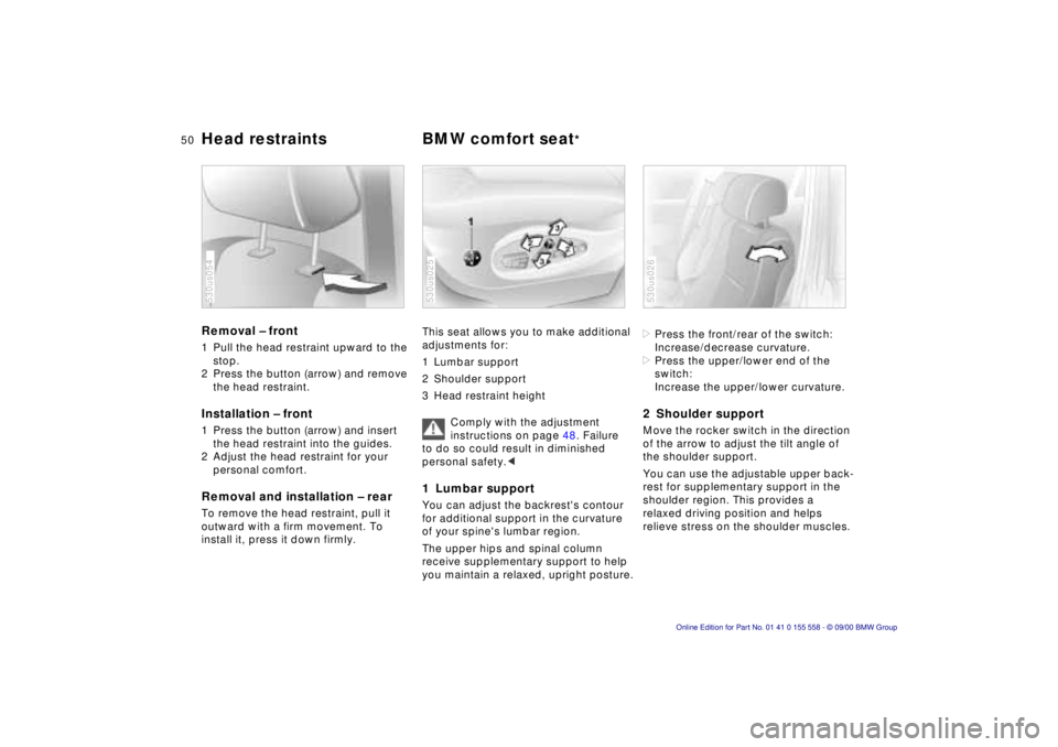
Removal – front
1 Pull the head restraint upward to the
stop.
2 Press the button (arrow) and remove the head restraint.
Installation – front
1 Press the button (arrow) and insert the head restraint into the guides.
2 Adjust the head restraint for your personal comfort.
Removal and installation – rear
To remove the head restraint, pull it
outward with a firm movement. To
install it, press it down firmly.
530us054
This seat allows you to make additional
adjustments for:
1 Lumbar support
2 Shoulder support
3 Head restraint height
Comply with the adjustment
instructions on page 48. Failure
to do so could result in diminished
personal safety. <
1 Lumbar support
You can adjust the backrest's contour
for additional support in the curvature
of your spine's lumbar region.
The upper hips and spinal column
receive supplementary support to help
you maintain a relaxed, upright posture.
530us025
>Press the front/rear of the switch:
Increase/decrease curvature.
> Press the upper/lower end of the
switch:
Increase the upper/lower curvature.
2 Shoulder support
Move the rocker switch in the direction
of the arrow to adjust the tilt angle of
the shoulder support.
You can use the adjustable upper back-
rest for supplementary support in the
shoulder region. This provides a
relaxed driving position and helps
relieve stress on the shoulder muscles.
530us026