ignition BMW X5 4.8IS 2004 E53 Owner's Manual
[x] Cancel search | Manufacturer: BMW, Model Year: 2004, Model line: X5 4.8IS, Model: BMW X5 4.8IS 2004 E53Pages: 200, PDF Size: 3.91 MB
Page 7 of 200
5n
OverviewControlsMaintenanceRepairsDataIndex
Controls and features
Passenger safety systems:
Airbags57
Transporting children safely59
Vehicle Memory,
Key Memory63
Driving:
Ignition lock64
Starting engine64
Switching off engine65
Handbrake66
Manual transmission66
Automatic transmission with
Steptronic67
Turn signals/
headlamp flasher70
Washer/wiper system/
rain sensor71
Cruise control73
Everything under control:
Odometer, outside temperature
display75
Tachometer76
Energy control76
Engine oil thermometer77
Fuel gauge77
Temperature gauge78
Service Interval Display78
Check Control79
Computer82
MID Multi-Information
Display83Digital clock in MID84
Computer in MID87
Technology for safety and
driving convenience:
PDC Park Distance Control92
Antilock Brake System93
DSC Dynamic Stability
Control94
xDrive95
HDC Hill Descent Control96
Self-leveling suspension97
2-axle self-leveling
suspension97
Brake Force Display99
Flat Tire Monitor100
Lamps:
Parking lamps/low beams102
Adaptive Head Light103
High beams/roadside parking
lamps103
Front fog lamps104
Instrument lighting104
Interior lamps104
Controlling climate for pleasant
driving:
Air conditioner106
Automatic climate control109
Roller sun blinds115
Independent ventilation115
Cabin convenience:
Integrated universal remote
control116
Telephone118
Glove compartment119
Storage compartments119
Cup holders120
Ashtray, front121
Ashtray, rear121
Cigarette lighter, rear122
Loading and transporting:
Ski bag123
Cargo area
Folding rear backrests
down124
Roll-up cover125
Partition net125
Cover panels in cargo
area127
Power outlets128
Pull-out cargo floor128
Cargo loading130
Roof-mounted luggage rack132
Page 21 of 200
19n
OverviewControlsMaintenanceRepairsDataIndex
Indicator and warning lamps
Technology that monitors itself
Indicator and warning lamps that are
identified by
+
are tested for proper
functioning whenever the ignition key is
turned. They each light up once for dif-
ferent periods of time.
If a fault should occur in one of the
monitored systems, the corresponding
lamp does not go out after the engine is
started or it lights up while the vehicle is
moving. You will see how to react to
this in the following section.
Red: stop immediately
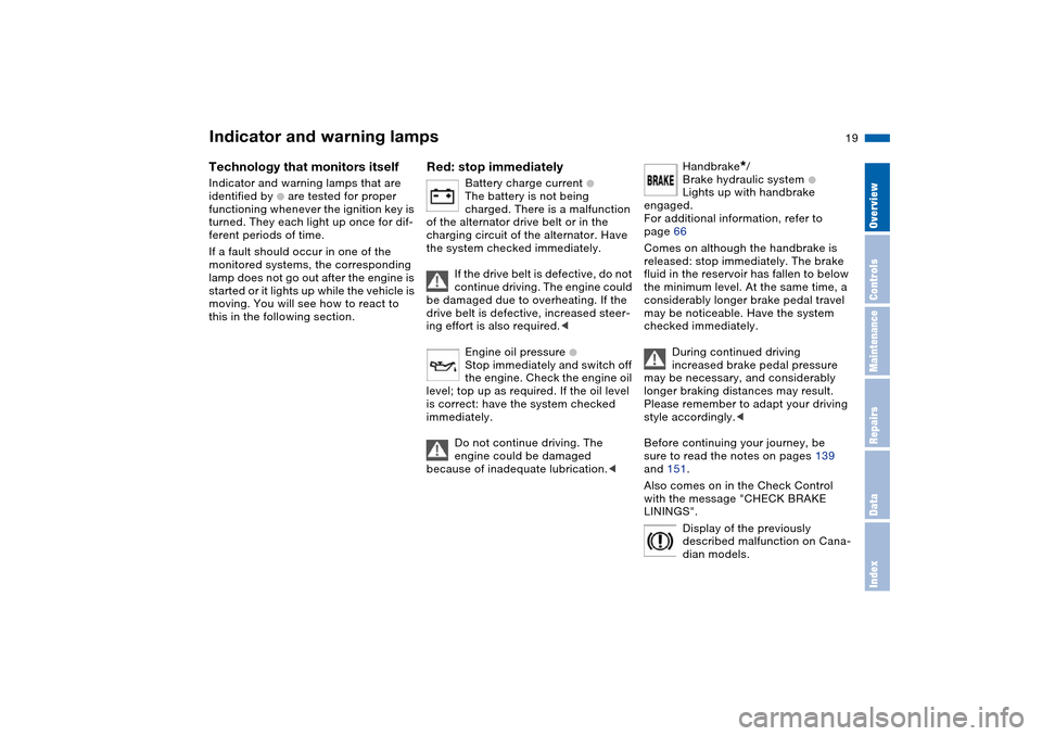
Battery charge current
+
The battery is not being
charged. There is a malfunction
of the alternator drive belt or in the
charging circuit of the alternator. Have
the system checked immediately.
If the drive belt is defective, do not
continue driving. The engine could
be damaged due to overheating. If the
drive belt is defective, increased steer-
ing effort is also required.<
Engine oil pressure +
Stop immediately and switch off
the engine. Check the engine oil
level; top up as required. If the oil level
is correct: have the system checked
immediately.
Do not continue driving. The
engine could be damaged
because of inadequate lubrication.<
Handbrake
*
/
Brake hydraulic system
+
Lights up with handbrake
engaged.
For additional information, refer to
page 66
Comes on although the handbrake is
released: stop immediately. The brake
fluid in the reservoir has fallen to below
the minimum level. At the same time, a
considerably longer brake pedal travel
may be noticeable. Have the system
checked immediately.
During continued driving
increased brake pedal pressure
may be necessary, and considerably
longer braking distances may result.
Please remember to adapt your driving
style accordingly.<
Before continuing your journey, be
sure to read the notes on pages 139
and 151.
Also comes on in the Check Control
with the message "CHECK BRAKE
LININGS".
Display of the previously
described malfunction on Cana-
dian models.
Page 32 of 200
30n
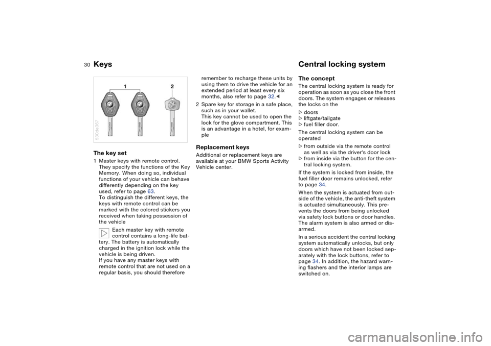
Keys Central locking system The key set 1Master keys with remote control.
They specify the functions of the Key
Memory. When doing so, individual
functions of your vehicle can behave
differently depending on the key
used, refer to page 63.
To distinguish the different keys, the
keys with remote control can be
marked with the colored stickers you
received when taking possession of
the vehicle
Each master key with remote
control contains a long-life bat-
tery. The battery is automatically
charged in the ignition lock while the
vehicle is being driven.
If you have any master keys with
remote control that are not used on a
regular basis, you should therefore 530de367
remember to recharge these units by
using them to drive the vehicle for an
extended period at least every six
months, also refer to page 32.<
2Spare key for storage in a safe place,
such as in your wallet.
This key cannot be used to open the
lock for the glove compartment. This
is an advantage in a hotel, for exam-
ple Replacement keys Additional or replacement keys are
available at your BMW Sports Activity
Vehicle center.
The concept The central locking system is ready for
operation as soon as you close the front
doors. The system engages or releases
the locks on the
>doors
>liftgate/tailgate
>fuel filler door.
The central locking system can be
operated
>from outside via the remote control
as well as via the driver's door lock
>from inside via the button for the cen-
tral locking system.
If the system is locked from inside, the
fuel filler door remains unlocked, refer
to page 34.
When the system is actuated from out-
side of the vehicle, the anti-theft system
is actuated simultaneously. This pre-
vents the doors from being unlocked
via safety lock buttons or door handles.
The alarm system is also armed or dis-
armed.
In a serious accident the central locking
system automatically unlocks, but only
doors which have not been locked sep-
arately with the lock buttons, refer to
page 34. In addition, the hazard warn-
ing flashers and the interior lamps are
switched on.
Page 41 of 200
39n
OverviewControlsMaintenanceRepairsDataIndex
Alarm system Windows>The indicator lamp flashes for
10 seconds after the vehicle is
unlocked: an attempted entry has
been detected in the period since the
system was armed.
Following triggering of an alarm, the
indicator lamp will flash continuously. Tilt alarm sensor and
interior motion sensor Tilt alarm sensor:
The tilt of the vehicle is monitored. The
alarm system reacts, for example, if
someone attempts to steal the wheels
or tow the vehicle.
Interior motion sensor:
In order for the interior motion sensor to
function properly, the windows and
panorama glass roof ‹must be com-
pletely closed.
Avoiding unintentional alarms The tilt alarm sensor and interior motion
sensor may be switched off at the same
time. This prevents unintentional
alarms, e.g. in the following situations:
>In duplex garages
>When transporting on car-carrying
trains
>If animals are to remain in the vehicle.
Switching off the tilt alarm sensor and
interior motion sensor:
Press the button on the remote control
twice consecutively.
The indicator lamp lights up briefly and
then flashes continuously. The tilt alarm
sensor and the interior motion sensor
are switched off up to the next unlock-
ing and locking actions.
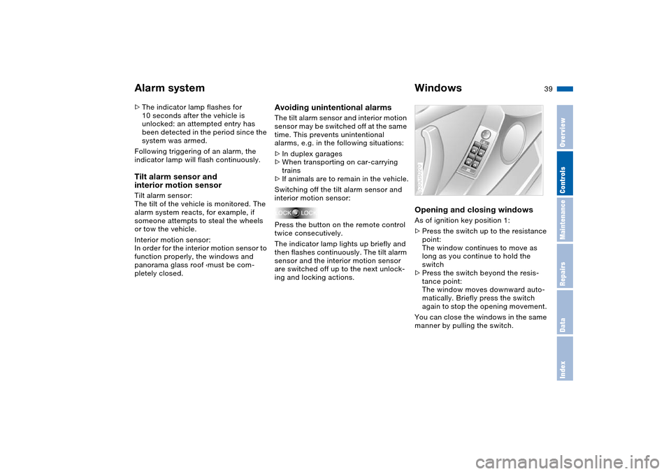
Opening and closing windows As of ignition key position 1:
>Press the switch up to the resistance
point:
The window continues to move as
long as you continue to hold the
switch
>Press the switch beyond the resis-
tance point:
The window moves downward auto-
matically. Briefly press the switch
again to stop the opening movement.
You can close the windows in the same
manner by pulling the switch.530us020
Page 42 of 200
40n
Windows After the ignition has been switched off:
>You can still operate the windows as
long as neither of the front doors has
been opened. To open the windows,
press the switch beyond the resis-
tance point.
When leaving the vehicle, always
remove the ignition key and close
the doors, as otherwise children could
operate the windows and injure them-
selves etc.<
For the convenience operation via the
remote control or the door lock, refer to
pages 31, 33. Anti-trapping mechanism A contact strip is integrated into the
inner side of each of the upper window
frame sections. If pressure is exerted
against this contact strip while a win-
dow is being raised, the system will
respond by stopping the window and
then retracting it a small distance.
Despite the anti-trapping mecha-
nism, be extremely careful that the
closing path of the window is not
obstructed whenever it is closed.
Otherwise, an object might not touch
the contact strip in some situations,
with very thin objects, for instance.
You can disable the anti-trapping
mechanism by pulling the switch
beyond the resistance point and hold-
ing it.
Because the power windows are sealed
at high pressure to prevent wind noise
when closed, a powerful motor is
required for efficient closing. When
closing the windows, always ensure
that they are not obstructed in any way.
Unsupervised use of these systems can
result in serious personal injury.
Remove the ignition key to deactivate
the power windows whenever you
leave the vehicle. Never leave the keys
in the vehicle with unsupervised chil-
dren. Never place anything that could
obstruct the driver's vision on or next to
the windows.<
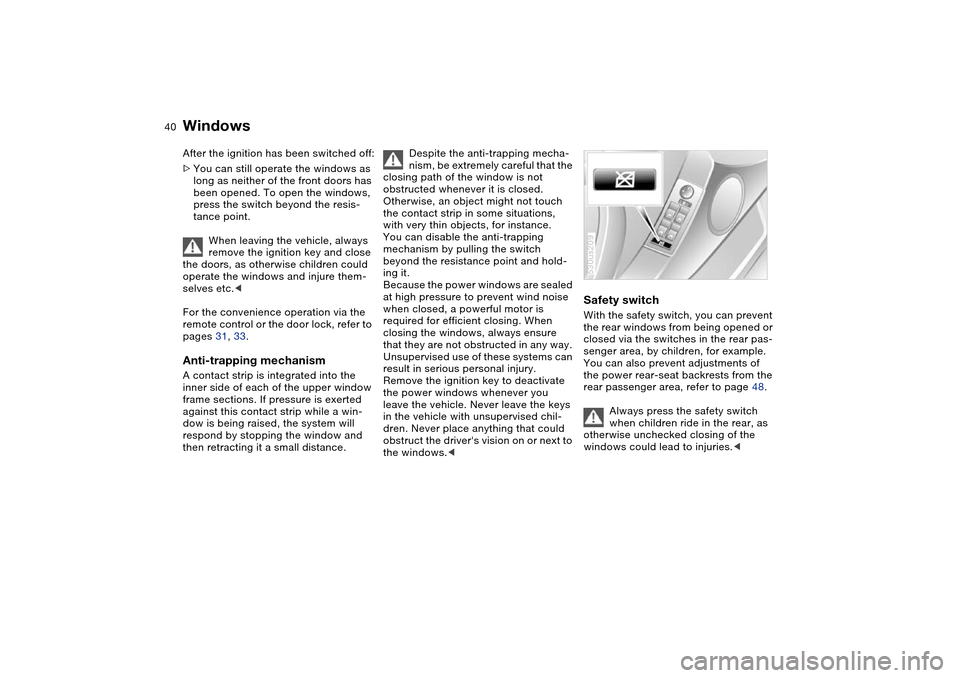
Safety switch With the safety switch, you can prevent
the rear windows from being opened or
closed via the switches in the rear pas-
senger area, by children, for example.
You can also prevent adjustments of
the power rear-seat backrests from the
rear passenger area, refer to page 48.
Always press the safety switch
when children ride in the rear, as
otherwise unchecked closing of the
windows could lead to injuries.<530us209
Page 43 of 200
41n
OverviewControlsMaintenanceRepairsDataIndex
Panorama glass roof
*
When leaving the vehicle, always
remove the ignition key and close
the doors, as otherwise children could
operate the roof and injure themselves
etc.<
The panorama glass roof is operational
from ignition key position 1.
After the ignition has been switched off:
You can operate the panorama glass
roof for up to 1 minute as long as nei-
ther of the doors has been opened.
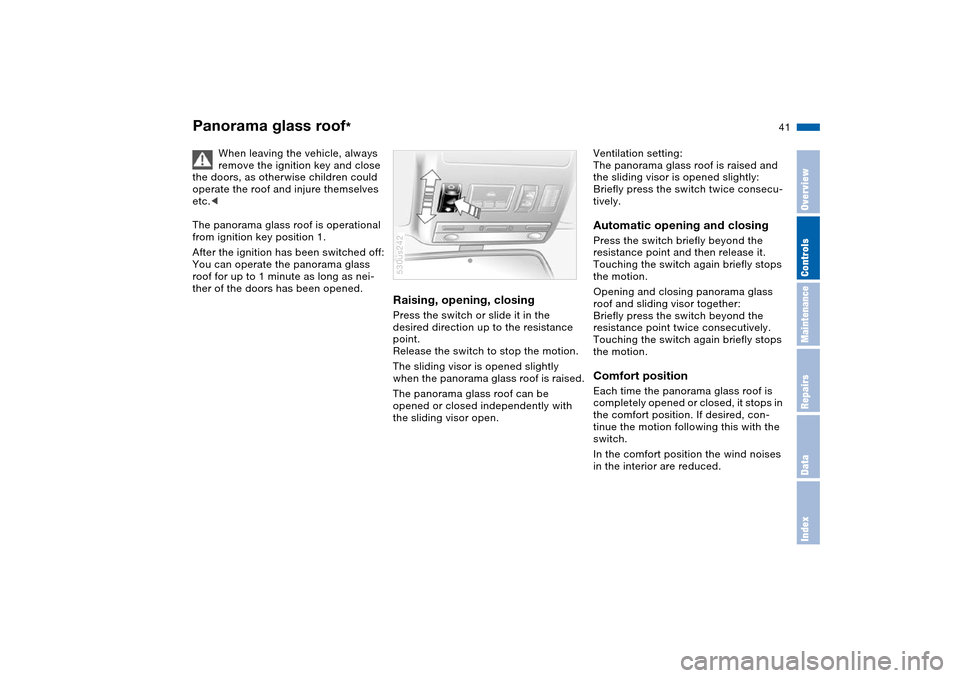
Raising, opening, closingPress the switch or slide it in the
desired direction up to the resistance
point.
Release the switch to stop the motion.
The sliding visor is opened slightly
when the panorama glass roof is raised.
The panorama glass roof can be
opened or closed independently with
the sliding visor open.530us242
Ventilation setting:
The panorama glass roof is raised and
the sliding visor is opened slightly:
Briefly press the switch twice consecu-
tively.Automatic opening and closing Press the switch briefly beyond the
resistance point and then release it.
Touching the switch again briefly stops
the motion.
Opening and closing panorama glass
roof and sliding visor together:
Briefly press the switch beyond the
resistance point twice consecutively.
Touching the switch again briefly stops
the motion.Comfort position Each time the panorama glass roof is
completely opened or closed, it stops in
the comfort position. If desired, con-
tinue the motion following this with the
switch.
In the comfort position the wind noises
in the interior are reduced.
Page 45 of 200
43n
OverviewControlsMaintenanceRepairsDataIndex
The ideal sitting position can make a
vital contribution to relaxed driving that
is as fatigue-free as possible. The sit-
ting position also plays an important
role together with the safety belts and
airbags in providing occupants with
maximum levels of passive safety in an
accident. To ensure that the safety sys-
tems operate with optimized efficiency,
we strongly urge you to observe the
instructions contained in the following
section.
For additional information on transport-
ing children safely, refer to page 59.Sitting safely with airbags
Always maintain an adequate dis-
tance between yourself and the
airbags. Always hold the steering wheel
by its rim with hands at the 9 o'clock
and 3 o'clock positions to minimize the
risk of injuries to your hands and arms
in the event of airbag deployment.
No one and nothing is to come between
the airbags and the seat occupant. Do
not use the cover of the front airbag on
the front passenger side as a storage
area. Make sure that the front passen-
ger is correctly seated and does not
rest feet or legs on the instrument clus-
ter, otherwise leg injuries can occur if
the knee and front airbag are triggered.
Never let an occupant's head rest near
or on a side airbag because the inflating
airbag could cause a serious or fatal
injury.<
Even if you adhere to all the instructions
injuries resulting from contact with air-
bags cannot be fully excluded, depend-
ing on the circumstances. The ignition
and inflation noise may provoke a mild –
usually temporary – hearing loss in
extremely sensitive individuals.
For airbag locations and additional
information on airbags, refer to
page 57.Sitting safely with safety belts Fasten your safety belt before starting
any trip. Airbags complement the safety
belt as an additional safety device, but
they do not represent a substitute.
Your vehicle has five seats that are all
equipped with a safety belt.
At all times, occupants should sit
upright and be properly restrained
– infants and small children in appropri-
ate child-restraint systems; larger chil-
dren and adults using the safety belts.
Even pregnant women should also
always wear the safety belt and espe-
cially ensure that the lap belt is posi-
tioned low on the hip and does not
press on the lower body.
Only one person should ever wear a
safety belt, and infants and children
may not be seated on the lap of another
passenger.
Do not route the belt across your neck,
or run it across sharp edges. Be sure
that the belt does not become caught
or jammed. Avoid twisting the belt while
routing it firmly across the hips and
shoulder. Do not allow the belt to rest
against hard or fragile objects. Other-
wise, in the event of a frontal impact, a
loose lap belt could slide over your
hips, leading to abdominal injury. Avoid
wearing clothing that prevents the belt
from fitting properly and pull the lap belt
periodically to readjust the tension
across your shoulder in order to avoid a
reduction in the retention effect of the
safety belt.<
For instructions on operating the safety
belt, refer to page 49.
Sitting safely
Page 52 of 200
50n
Seat, mirror and steering wheel memory
*
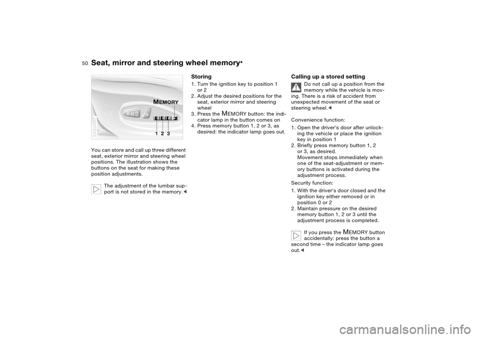
You can store and call up three different
seat, exterior mirror and steering wheel
positions. The illustration shows the
buttons on the seat for making these
position adjustments.
The adjustment of the lumbar sup-
port is not stored in the memory.<530us032
Storing 1. Turn the ignition key to position 1
or 2
2. Adjust the desired positions for the
seat, exterior mirror and steering
wheel
3. Press the
M
EMORY button: the indi-
cator lamp in the button comes on
4. Press memory button 1, 2 or 3, as
desired: the indicator lamp goes out.
Calling up a stored setting
Do not call up a position from the
memory while the vehicle is mov-
ing. There is a risk of accident from
unexpected movement of the seat or
steering wheel.<
Convenience function:
1. Open the driver's door after unlock-
ing the vehicle or place the ignition
key in position 1
2. Briefly press memory button 1, 2
or 3, as desired.
Movement stops immediately when
one of the seat-adjustment or mem-
ory buttons is activated during the
adjustment process.
Security function:
1. With the driver's door closed and the
ignition key either removed or in
position 0 or 2
2. Maintain pressure on the desired
memory button 1, 2 or 3 until the
adjustment process is completed.
If you press the
M
EMORY button
accidentally: press the button a
second time – the indicator lamp goes
out.<
Page 54 of 200
52n
Heated seats
*
Steering wheel
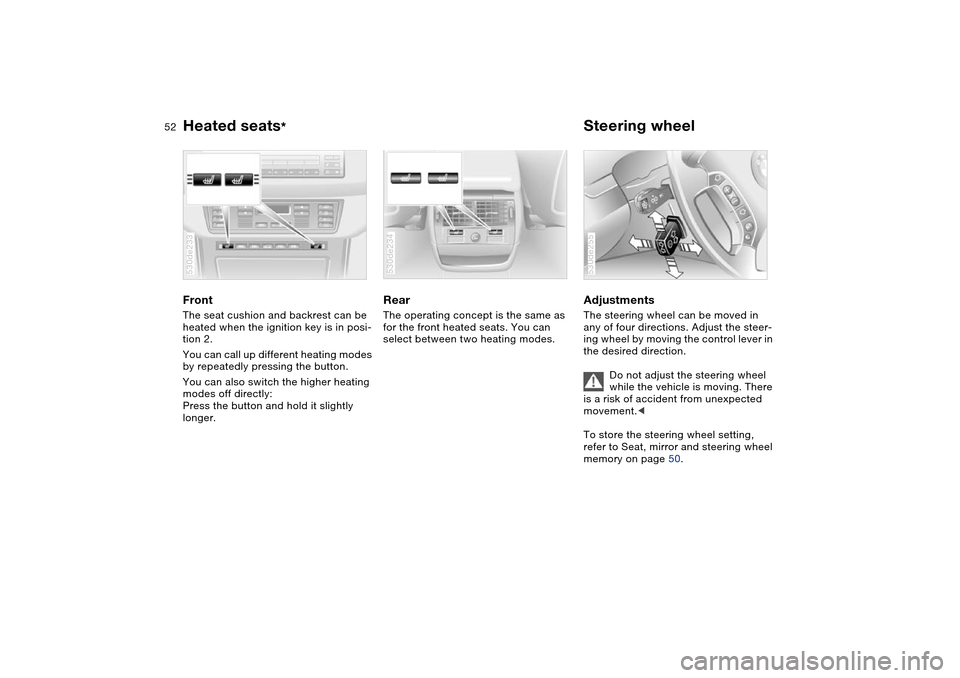
Front The seat cushion and backrest can be
heated when the ignition key is in posi-
tion 2.
You can call up different heating modes
by repeatedly pressing the button.
You can also switch the higher heating
modes off directly:
Press the button and hold it slightly
longer.530de233
Rear The operating concept is the same as
for the front heated seats. You can
select between two heating modes.530de234
Adjustments The steering wheel can be moved in
any of four directions. Adjust the steer-
ing wheel by moving the control lever in
the desired direction.
Do not adjust the steering wheel
while the vehicle is moving. There
is a risk of accident from unexpected
movement.<
To store the steering wheel setting,
refer to Seat, mirror and steering wheel
memory on page 50. 530de255
Page 55 of 200
53n
OverviewControlsMaintenanceRepairsDataIndex
Steering wheel Steering wheel heater
*
Automatic steering wheel
adjustmentonly in conjunction with seat, mirror and
steering wheel memory
In order to make it easier to get into and
out of the vehicle, the steering wheel
automatically moves into the top posi-
tion and returns to the driving or mem-
ory position.
This automatic feature is controlled by
the position of the ignition key and by
the driver's door.
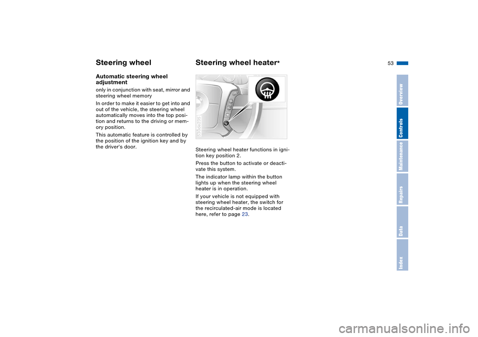
Steering wheel heater functions in igni-
tion key position 2.
Press the button to activate or deacti-
vate this system.
The indicator lamp within the button
lights up when the steering wheel
heater is in operation.
If your vehicle is not equipped with
steering wheel heater, the switch for
the recirculated-air mode is located
here, refer to page 23.
530de235