service BMW X5 XDRIVE 35I 2013 User Guide
[x] Cancel search | Manufacturer: BMW, Model Year: 2013, Model line: X5 XDRIVE 35I, Model: BMW X5 XDRIVE 35I 2013Pages: 345, PDF Size: 9.45 MB
Page 56 of 345

BMW X5: push the head restraints of the 3rd
row seats into the top position.
Height
Adjust the head restraint so that its center is
approx. at ear level.
Distance Adjust the distance so that the head restraint
is as close as possible to the back of the head.
Active front head restraints
In the event of a rear-end collision of sufficient
severity, the active head restraint reduces the
distance to the head.
Reduced protective function▷Do not use seat or head restraint
covers.▷Do not hang objects, e.g., clothes hangers,
directly on the head restraints.▷Only attach accessories approved by BMW
to the seat or head restraint.
Otherwise, the protective function of the active
head restraint will be impaired and the per‐
sonal safety of the occupants will be endan‐
gered.
Have the active head restraints reset after they
are triggered in a rear-end collision. Have this
work performed by the service center only;
otherwise, this safety feature with not be op‐
erational.◀
Please contact the service center if the front
head restraints need to be removed or instal‐
led.
Front seats: adjusting the height
Adjust the head restraint so that its center is
approx. at ear level.
Electrical
Adjusting electrically.
Front seats: adjusting the distance
from the back of the head
Press the button and pull the headrest cushion
forward or push it back.
Compromised performance
Do not place any objects behind the
headrest cushion. Otherwise, you can impair
the proper function of the head restraint.◀
Comfort seat The distance from the back of the seat occu‐
pant's head can be adjusted using the
shoulder support, refer to page 50.
Seite 56ControlsAdjusting56
Online Edition for Part no. 01 40 2 918 395 - III/13
Page 72 of 345

cargo floor panel, refer to page 295, into
the loop of the release point, see arrow.4.Forcefully pull the screwdriver up against
the mechanical resistance until there is a
marked increase in resistance and the
parking brake can be heard to unlock.5.Stow the screwdriver, warning triangle, and
first aid kit and close the left side panel in
the cargo area.
Have the malfunction corrected
Have the malfunction corrected at the
nearest service center or at a workshop that
works according to BMW repair procedures
with correspondingly trained personnel. If the
parking brake has been released manually in
response to a malfunction, only technicians
can return it to operation.◀
Following manual release, the actual status of
the parking brake may deviate from that dis‐
played by the indicator lamp.
Putting into operation after a power failure
Putting the parking brake into operation
The parking brake should only be put
into operation again if it was manually released
due to an interruption in the supply of electrical
power. Otherwise the operation of the parking
brake is not ensured and there is a danger of
the vehicle rolling despite the parking brake
being set.◀
Procedure1.Switch on the ignition.2.Press the button with the brake depressed.
The indicator lamp in the instrument
cluster goes out as soon as the parking
brake is ready for operation.
Indicator lamp in Canadian models.
Any noises which occur are normal. Startup
may take several seconds.
Turn signal, high beams,
headlamp flasher
At a glance
1High beams2Headlamp flasher3Turn signal
Turn signal
Press the lever beyond the resistance point.
To switch off manually, press the lever to the
resistance point.
Unusually rapid flashing of the indicator lamp
indicates that a turn signal bulb has failed.
Signaling a turn briefly
Press the lever to the resistance point and hold
it there for as long as you want the turn signal
to flash.
Seite 72ControlsDriving72
Online Edition for Part no. 01 40 2 918 395 - III/13
Page 79 of 345

DisplaysVehicle equipmentThis chapter describes all series equipment as
well as country-specific and special equipment
offered for this model series.Therefore, it also
describes equipment that may not be found in
your vehicle, for instance due to the selected
special equipment or the country version. This
also applies to safety-related functions and
systems.
Odometer, external
temperature display, clock1Knob in the instrument cluster2Time, external temperature, and date3Odometer and trip odometer
Knob in the instrument cluster
Press the knob.
▷When the ignition is switched on, the trip
odometer is reset.
Press the knob for approx. 5 seconds:
View service requirement display, refer to
page 83▷When the ignition is switched off, the time,
external temperature and odometer are
displayed.Units of measure
To set the respective units of measure, miles
or km for the odometer and ℃ or ℉ for the ex‐
ternal temperature, refer to page 88.
The setting is stored for the remote control
currently in use.
Time, date, external temperature From radio readiness the external temperature
and the time are displayed.
Set the time, refer to page 87.
Retrieving date
Press the button on turn signal lever upward;
the date appears.
Set the date, refer to page 87.
Pressing the button upward or downward sev‐
eral times changes the display between clock,
external temperature, date, and Check Control
messages, refer to page 85.
External temperature warning If the display drops to +37 ℉/+3 ℃, a signal
sounds and a warning lamp lights up. There is
the increased danger of ice.
Ice on roads
Even at temperatures above
+37 ℉/+3 ℃, there can be a risk of ice on
roads.
Seite 79DisplaysControls79
Online Edition for Part no. 01 40 2 918 395 - III/13
Page 83 of 345

Resetting the trip computerResetting all values:1."Vehicle Info"2."Trip computer"3."Reset"
Service requirements
The remaining driving distance and the date of
the next scheduled service are displayed
briefly immediately after you start the engine
or switch on the ignition.
The current service requirements can be read
out from the remote control by the service
specialist.
For certain maintenance operations, you can
view the distance remaining or the due date for
that operation in the instrument cluster.
1.With the ignition switched on, press the
knob in the instrument cluster, refer to
page 79, for approx. 5 seconds until the
service requirements are displayed.2.Press the knob repeatedly to display the
individual service requirement items.DisplaysSymbolFunctionService requirementsEngine oilRoadworthiness testFront brake padsRear brake padsBrake fluid
The sequence of displayed service items may
vary. First the data for the next maintenance
are displayed.
Seite 83DisplaysControls83
Online Edition for Part no. 01 40 2 918 395 - III/13
Page 84 of 345
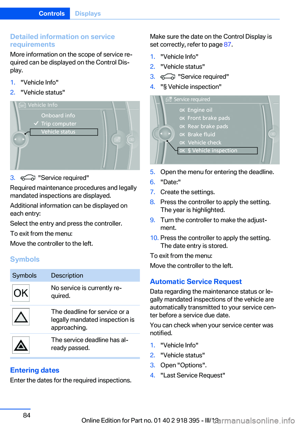
Detailed information on service
requirements
More information on the scope of service re‐
quired can be displayed on the Control Dis‐
play.1."Vehicle Info"2."Vehicle status"3. "Service required"
Required maintenance procedures and legally
mandated inspections are displayed.
Additional information can be displayed on
each entry:
Select the entry and press the controller.
To exit from the menu:
Move the controller to the left.
Symbols
SymbolsDescriptionNo service is currently re‐
quired.The deadline for service or a
legally mandated inspection is
approaching.The service deadline has al‐
ready passed.
Entering dates
Enter the dates for the required inspections.
Make sure the date on the Control Display is
set correctly, refer to page 87.1."Vehicle Info"2."Vehicle status"3. "Service required"4."§ Vehicle inspection"5.Open the menu for entering the deadline.6."Date:"7.Create the settings.8.Press the controller to apply the setting.
The year is highlighted.9.Turn the controller to make the adjust‐
ment.10.Press the controller to apply the setting.
The date entry is stored.
To exit from the menu:
Move the controller to the left.
Automatic Service Request
Data regarding the maintenance status or le‐
gally mandated inspections of the vehicle are
automatically transmitted to your service cen‐
ter before a service due date.
You can check when your service center was
notified.
1."Vehicle Info"2."Vehicle status"3.Open "Options".4."Last Service Request"Seite 84ControlsDisplays84
Online Edition for Part no. 01 40 2 918 395 - III/13
Page 85 of 345

Check Control
The concept The Check Control monitors vehicle functions
and alerts you to any malfunctions in the sys‐
tems monitored.
A Check Control message consists of indicator and warning lamps in the instrument cluster
and, in some circumstances, an acoustic signal
and text messages at the top of the Control
Display.
Indicator/warning lamps
The indicator and warning lamps can light up in
a variety of combinations and colors.
Several of the lamps are checked for proper
functioning and light up temporarily when the
engine is started or the ignition is switched on.
The symbol indicates that Check Control
messages have been stored. The Check Con‐
trol messages can be displayed later.
Text messages Text messages at the upper edge of the Con‐
trol Display in combination with a symbol in the
instrument cluster explain a Check Control
message and the meaning of the indicator and
warning lamps.
Supplementary text messages
Addition information, such as on the cause of a
fault or the required action, can be called up via
Check Control.
In urgent cases, this information will be shown
as soon as the corresponding lamp comes on.
Symbols
The following functions can be selected within
the supplementary text message, depending
on the Check Control message.▷ "Service request"
Contact the service partner.▷ "Roadside Assistance"
Contact Roadside Assistance.
Hiding Check Control messages
Press the button in the turn signal lever up or
down.
▷Some Check Control messages are dis‐
played continuously and are not cleared
until the malfunction is eliminated. If sev‐
eral malfunctions occur at once, the mes‐
sages are displayed consecutively.
These messages can be hidden for approx.
8 seconds. After this time, they are dis‐
played again automatically.▷Other Check Control messages are hidden
automatically after approx. 20 seconds.Seite 85DisplaysControls85
Online Edition for Part no. 01 40 2 918 395 - III/13
Page 96 of 345

▷Make sure that the front passenger is sit‐
ting correctly, i.e., keeps his or her feet and
legs in the footwell; otherwise, leg injuries
can occur if the front airbag is triggered.▷Do not place slip covers, seat cushions or
other objects on the front passenger seat
that are not approved specifically for seats
with integrated side airbags.▷Do not hang pieces of clothing, such as
jackets, over the backrests.▷Make sure that occupants keep their heads
away from the side airbag and do not rest
against the head airbag; otherwise, injuries
can occur if the airbags are triggered.▷Do not remove the airbag restraint system.▷Do not remove the steering wheel.▷Do not apply adhesive materials to the air‐
bag cover panels, cover them or modify
them in any way.▷Never modify either the individual compo‐
nents or the wiring in the airbag system.
This also applies to steering wheel covers,
the dashboard, the seats, the roof pillars
and the sides of the headliner.◀
Even when all instructions are followed closely,
injury from contact with the airbags cannot be
ruled out in certain situations.
The ignition and inflation noise may lead to
short-term and, in most cases, temporary
hearing impairment in sensitive individuals.
In the case of a malfunction, deactivation
and after triggering of the airbags
Do not touch the individual components imme‐
diately after the system has been triggered;
otherwise, there is the danger of burns.
Only have the airbags checked, repaired or dis‐
mantled and the airbag generator scrapped by
your service center or a workshop that has the
necessary authorization for handling explo‐
sives.
Non-professional attempts to service the sys‐
tem could lead to failure in an emergency or
undesired triggering of the airbag, either of
which could result in injury.◀
Warnings and information on the airbags are
also found on the sun visors.
Automatic deactivation of the frontpassenger airbags
The occupation of the seat is detected by eval‐
uating the impression on the occupied seat
surface of the front passenger seat.
The front and side airbags on the front passen‐
ger side are activated or deactivated accord‐
ingly by the system.
The indicator lamp above the interior rearview
mirror shows the current status of the front
passenger airbags, deactivated or activated,
refer to Front passenger airbag indicator lamp
below.
Leave feet in the footwell
Make sure that the front passenger
keeps his or her feet in the footwell; otherwise,
the front passenger airbags may not function
properly.◀
Child restraint fixing system in the front
passenger seat
Before transporting a child on the front pas‐
senger seat, refer to the safety notes and in‐
structions under Children on the front passen‐
ger seat, refer to page 61.◀
Malfunction of the automatic
deactivation system
When transporting older children and adults,
the front passenger airbags may be deacti‐
vated in certain sitting positions. In this case,
the indicator lamp for the front passenger air‐ bags lights up.
In this case, change the sitting position so that
the front passenger airbags are activated and
the indicator lamp goes out.Seite 96ControlsSafety96
Online Edition for Part no. 01 40 2 918 395 - III/13
Page 99 of 345

Actions in the event of a flat tire
Run-flat tires Maximum speed
You can continue driving with a damaged tire
at speeds up to 50 mph/80 km/h.
Continued driving with a flat tire
If continuing to drive with a damaged tire:1.Avoid sudden braking and steering maneu‐
vers.2.Do not exceed a speed of 50 mph/80 km/h.
If the defective tire continues to lose pres‐
sure, its position will be indicated to you on
the Control Display.3.At the next opportunity, check the inflation
pressure in all four tires.
If the tire inflation pressure in all four tires
is correct, the Flat Tire Monitor may not
have been initialized. In this case, initialize
the system.
Possible driving distance with complete loss of
tire inflation pressure:
The possible driving distance after a loss of tire
inflation pressure depends on the cargo load
and the driving style and conditions.
For a vehicle containing an average load, the
possible driving distance is ap‐
prox. 50 miles/80 km.
When the vehicle is driven with a damaged tire,
its handling characteristics change, e.g., re‐
duced lane stability during braking, a longer
braking distance, and altered self-steering
properties. Adjust your driving style accord‐
ingly. Avoid abrupt steering maneuvers or driv‐
ing over obstacles, e. g., curbs, potholes, etc.
Because the possible driving distance de‐
pends on how the vehicle is used during the
trip, the actual distance may be smaller or
greater depending on the driving speed, road
conditions, external temperature, cargo load,
etc.
Continued driving with a flat tire
Drive moderately and do not exceed a
speed of 50 mph/80 km/h.
A loss of tire inflation pressure results in a
change in the handling characteristics, e.g., re‐
duced lane stability during braking, a longer
braking distance and altered self-steering
properties.◀
Final tire failure
Vibrations or loud noises while driving
can indicate the final failure of the tire. Reduce
speed and stop; otherwise, pieces of the tire
could come loose and cause an accident. Do
not continue driving, and contact your service
center.◀
Tire Pressure Monitor TPMThe concept
The tire inflation pressure is measured in the
four mounted tires. The system notifies you if
there is a significant loss of pressure in one or
more tires.
Functional requirements The system must have been reset while the in‐
flation pressure was correct; otherwise, reliable
signaling of a flat tire is not ensured.
Always use wheels with TPM electronics to
ensure that the system will operate properly.
Reset the system after each correction of the
tire inflation pressure and after every tire or
wheel change.
System limits Sudden tire damage
Sudden serious tire damage caused by
external influences cannot be indicated in ad‐
vance.◀
The system does not operate correctly if it has
not been reset. For example, a flat tire may beSeite 99SafetyControls99
Online Edition for Part no. 01 40 2 918 395 - III/13
Page 101 of 345

▷There is a flat tire or a major loss in tire in‐
flation pressure.▷The system was not reset after a wheel
change and thus issues warnings based on
the inflation pressures initialized last.
Reduce your speed and stop cautiously. Avoid
sudden braking and steering maneuvers.
Do not continue driving without run-flat
tires
If the vehicle is not equipped with run-flat tires
as provided at the factory, do not continue
driving. Continuing to drive could cause severe
accidents.◀
When a low inflation pressure is indicated,
DSC Dynamic Stability Control is switched on
if necessary.
Actions in the event of a flat tire Run-flat tires Maximum speed
You can continue driving with a damaged tire
at speeds up to 50 mph/80 km/h.
Continued driving with a flat tire
If continuing to drive with a damaged tire:
1.Avoid sudden braking and steering maneu‐
vers.2.Do not exceed a speed of 50 mph/80 km/h.3.Check the air pressure in all four tires at
the next opportunity.
If the tire inflation pressure in all four tires
is correct, the Tire Pressure Monitor may
not have been reset. Reset the system.
Possible driving distance with complete loss of
tire inflation pressure:
The possible driving distance after a loss of tire
inflation pressure depends on the cargo load
and the driving style and conditions.
For a vehicle containing an average load, the
possible driving distance is ap‐
prox. 50 miles/80 km.
When the vehicle is driven with a damaged tire,
its handling characteristics change, e.g., re‐
duced lane stability during braking, a longer
braking distance, and altered self-steering
properties. Adjust your driving style accord‐
ingly. Avoid abrupt steering maneuvers or driv‐
ing over obstacles, e. g., curbs, potholes, etc.
Because the possible driving distance de‐
pends on how the vehicle is used during the
trip, the actual distance may be smaller or
greater depending on the driving speed, road
conditions, external temperature, cargo load,
etc.
Continued driving with a flat tire
Drive moderately and do not exceed a
speed of 50 mph/80 km/h.
A loss of tire inflation pressure results in a
change in the handling characteristics, e.g., re‐
duced lane stability during braking, a longer
braking distance and altered self-steering
properties.◀
Final tire failure
Vibrations or loud noises while driving
can indicate the final failure of the tire. Reduce
speed and stop; otherwise, pieces of the tire
could come loose and cause an accident. Do
not continue driving, and contact your service
center.◀
Message when the system was not
reset
The yellow warning lamp lights up. A
message appears on the Control Dis‐
play.
The system detected a wheel change but was
not reset.
Warnings regarding the current tire inflation
pressure are not reliable.Seite 101SafetyControls101
Online Edition for Part no. 01 40 2 918 395 - III/13
Page 102 of 345

Check the tire inflation pressure and reset the
system.
Malfunction The small warning lamp flashes inyellow and then lights up continu‐
ously; the larger warning lamp comes
on in yellow. On the Control Display,
the tires are shown in gray and a message ap‐
pears. No flat tire can be detected.
Display in the following situations:▷If a wheel without TPM electronics is fitted,
for instance a compact wheel: have the
service center check it if necessary.▷Malfunction: have the system checked by
your service center.▷TPM could not be fully reset. Reset the
system again.▷Disturbance by systems or devices with
the same radio frequency: after leaving the
area of the disturbance, the system auto‐
matically becomes active again.
Declaration according to NHTSA/
FMVSS 138 Tire Pressure Monitoring
Systems
Each tire, including the spare (if provided)
should be checked monthly when cold and in‐
flated to the inflation pressure recommended
by the vehicle manufacturer on the vehicle
placard or tire inflation pressure label (If your
vehicle has tires of a different size than the size
indicated on the vehicle placard or tire inflation
pressure label, you should determine the
proper tire inflation pressure for those tires.).
As an added safety feature, your vehicle has
been equipped with a tire pressure monitoring
system (TPMS) that illuminates a low tire pres‐
sure telltale when one or more of your tires is
significantly under-inflated. Accordingly, when
the low tire pressure telltale illuminates, you
should stop and check your tires as soon as
possible, and inflate them to the proper pres‐
sure. Driving on a significantly under-inflated
tire causes the tire to overheat and can lead to
tire failure. Under-inflation also reduces fuel ef‐
ficiency and tire tread life, and may affect the
vehicle's handling and stopping ability.
Please note that the TPMS is not a substitute
for proper tire maintenance, and it is the driv‐
er's responsibility to maintain correct tire pres‐
sure, even if under-inflation has not reached
the level to trigger illumination of the TPMS
low tire pressure telltale.
Your vehicle has also been equipped with a
TPMS malfunction indicator to indicate when
the system is not operating properly. The
TPMS malfunction indicator is combined with
the low tire pressure telltale. When the system
detects a malfunction, the telltale will flash for
approximately one minute and then remain
continuously illuminated. This sequence will
continue upon subsequent vehicle startups as
long as the malfunction exists. When the mal‐
function indicator is illuminated, the system
may not be able to detect or signal low tire
pressure as intended. TPMS malfunctions may
occur for a variety of reasons, including the in‐
stallation of replacement or alternate tires or
wheels on the vehicle that prevent the TPMS
from functioning properly. Always check the
TPMS malfunction telltale after replacing one
or more tires or wheels on your vehicle to en‐
sure that the replacement or alternate tires and
wheels allow the TPMS to continue to function
properly.
Lane departure warning
The concept This system issues a warning at speeds above
approx. 40 mph/65 km/h if the vehicle is about
to leave the lane on roads with lane markings.
The steering wheel begins vibrating lightly.
The time when the warning is issued may vary
with the current driving situation.
The system does not issue a warning if the
turn signal is set before leaving the lane.Seite 102ControlsSafety102
Online Edition for Part no. 01 40 2 918 395 - III/13