tow BMW X5M 2014 F85 User Guide
[x] Cancel search | Manufacturer: BMW, Model Year: 2014, Model line: X5M, Model: BMW X5M 2014 F85Pages: 251, PDF Size: 7.35 MB
Page 108 of 251
▷High beams off/headlight flasher, arrow 2.
The High-beam Assistant can be switched off
when manually adjusting the light. To reacti‐
vate the High-beam Assistant, press the but‐
ton on the turn signal lever.
System limits Personal responsibility
The High-beam Assistant cannot serve
as a substitute for the driver's personal judg‐
ment of when to use the high beams. There‐
fore, manually reel off the high beams in situa‐
tions where required to avoid a safety risk.◀
The system is not fully functional in situations
such as the following, and driver intervention
may be necessary:
▷In very unfavorable weather conditions,
such as fog or heavy precipitation.▷When detecting poorly-lit road users such
as pedestrians, cyclists, horseback riders
and wagons; when driving close to train or
ship traffic; and at animal crossings.▷In tight curves, on hilltops or in depres‐
sions, in cross traffic or half-obscured on‐
coming traffic on freeways.▷In poorly-lit towns and cities and in the
presence of highly reflective signs.▷At low speeds.▷When the windshield behind the interior
rearview mirror is fogged over, dirty or cov‐
ered with stickers, etc.
Fog lights
Front fog lights
The low beams must be switched on.
Press button. The green indicator
lamp lights up.
If the automatic headlight control, refer to
page 102, is activated, the low beams will
come on automatically when you reel on the
front fog lights.
When the high beams or headlight flasher are
activated, the front fog lights are not switched
on.
Instrument lighting Adjusting The parking lights or low beams
must be switched on to adjust
the brightness.
Adjust the brightness with the
thumbwheel.
Interior lights
General information The interior lights, footwell lights, access lights
and courtesy lights are controlled automati‐
cally.
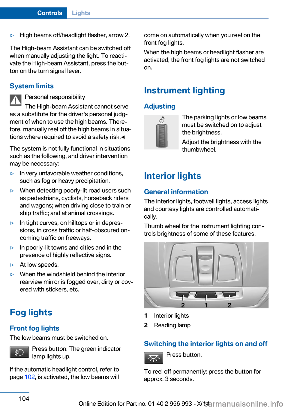
Thumb wheel for the instrument lighting con‐
trols brightness of some of these features.1Interior lights2Reading lamp
Switching the interior lights on and off
Press button.
To reel off permanently: press the button for
approx. 3 seconds.
Seite 104ControlsLights104
Online Edition for Part no. 01 40 2 956 993 - X/14
Page 120 of 251
Braking intervention
The warning prompts the driver himself/herself
to react. During a warning, the maximum brak‐
ing force is used. Premise for the brake boos‐
ter is sufficiently quick and hard stepping on
the brake pedal. The system can assist with
some braking intervention if there is risk of a
collision. At low speeds vehicles may thus
come to a complete stop.
The braking intervention is executed only if
DSC Dynamic Stability Control is switched on
and M Dynamic mode MDM is not activated.
The braking intervention can be interrupted by
stepping on the accelerator pedal or by ac‐
tively moving the steering wheel.
Object detection can be restricted. Limitations
of the detection range and functional restric‐
tions are to be considered.
Tow-starting and towing
For towing the vehicle turn, switch off the
Intelligent Safety systems; otherwise malfunc‐
tions of the individual braking systems might
lead to accidents.◀
System limits Be alert
Due to system limitations, warnings may
be not issued at all, or may be issued late or
improperly. Therefore, always be alert and
ready to intervene; otherwise, there is the risk
of an accident.◀
Detection range
The system's detection potential is limited.
Thus a warning might not be issued or be is‐
sued late.
E. g. the following situations may not be de‐
tected:▷Slow moving vehicles when you approach
them at high speed.▷Vehicles that suddenly swerve in front of
you, or sharply decelerating vehicles.▷Vehicles with an unusual rear appearance.▷Two-wheeled vehicles ahead of you.
Functional limitations
The system may not be fully functional in the
following situations:
▷In heavy fog, rain, sprayed water or snow‐
fall.▷In tight curves.▷If the driving stability control systems are
limited or deactivated, e.g., DSC OFF.▷If the field of view of the camera in the mir‐
ror is dirty or obscured.▷Up to 10 seconds after the start of the en‐
gine, via the Start/Stop knob.▷During calibration of the camera immedi‐
ately after vehicle shipment.▷If there is constant blinding effects be‐
cause of oncoming light, e.g., from the sun
low in the sky.
Warning sensitivity
The more sensitive the warning settings are,
the more warnings are displayed. However,
there may also be an excess of false warnings.
Pedestrian warning
Depending on how the vehicle is equipped, the
function warns of an imminent collision with
pedestrians during daytime or nighttime.
The function is subdivided into the following
systems:
▷During daytime: Pedestrian warning with
city braking function, refer to page 117▷At night: Night vision, refer to page 119Seite 116ControlsSafety116
Online Edition for Part no. 01 40 2 956 993 - X/14
Page 122 of 251
Camera
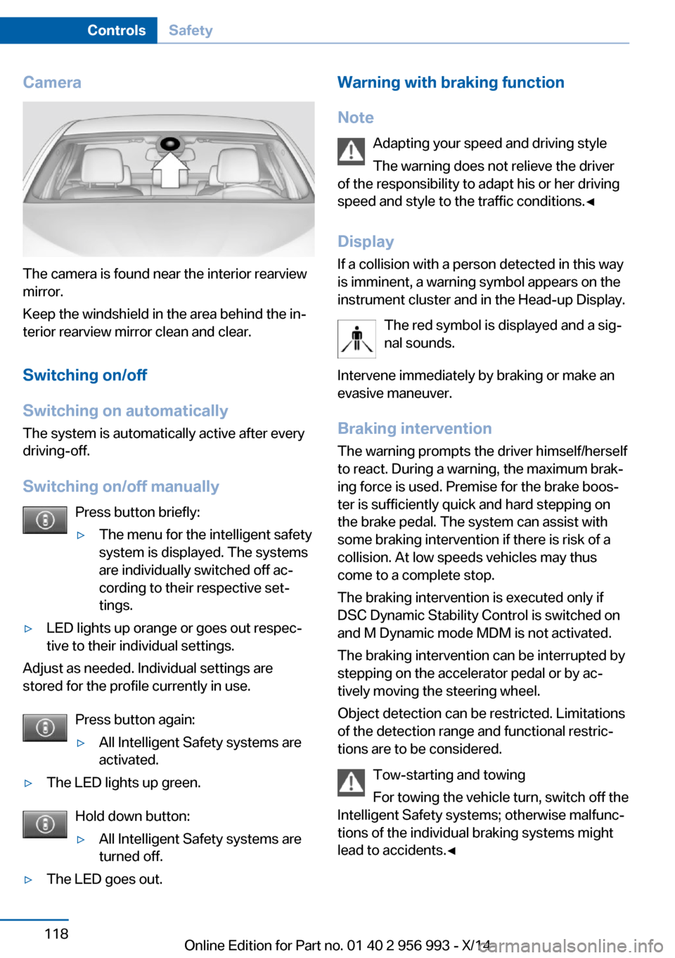
The camera is found near the interior rearview
mirror.
Keep the windshield in the area behind the in‐
terior rearview mirror clean and clear.
Switching on/off
Switching on automatically The system is automatically active after every
driving-off.
Switching on/off manually Press button briefly:
▷The menu for the intelligent safety
system is displayed. The systems
are individually switched off ac‐
cording to their respective set‐
tings.▷LED lights up orange or goes out respec‐
tive to their individual settings.
Adjust as needed. Individual settings are
stored for the profile currently in use.
Press button again:
▷All Intelligent Safety systems are
activated.▷The LED lights up green.
Hold down button:
▷All Intelligent Safety systems are
turned off.▷The LED goes out.Warning with braking function
Note Adapting your speed and driving styleThe warning does not relieve the driver
of the responsibility to adapt his or her driving
speed and style to the traffic conditions.◀
Display If a collision with a person detected in this way
is imminent, a warning symbol appears on the
instrument cluster and in the Head-up Display.
The red symbol is displayed and a sig‐
nal sounds.
Intervene immediately by braking or make an
evasive maneuver.
Braking intervention The warning prompts the driver himself/herself
to react. During a warning, the maximum brak‐
ing force is used. Premise for the brake boos‐
ter is sufficiently quick and hard stepping on
the brake pedal. The system can assist with
some braking intervention if there is risk of a
collision. At low speeds vehicles may thus
come to a complete stop.
The braking intervention is executed only if
DSC Dynamic Stability Control is switched on
and M Dynamic mode MDM is not activated.
The braking intervention can be interrupted by
stepping on the accelerator pedal or by ac‐
tively moving the steering wheel.
Object detection can be restricted. Limitations
of the detection range and functional restric‐
tions are to be considered.
Tow-starting and towing
For towing the vehicle turn, switch off the
Intelligent Safety systems; otherwise malfunc‐
tions of the individual braking systems might
lead to accidents.◀Seite 118ControlsSafety118
Online Edition for Part no. 01 40 2 956 993 - X/14
Page 126 of 251
Warning area in front of the vehicle
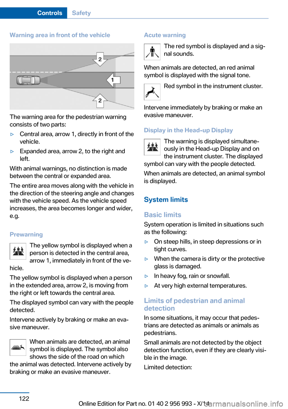
The warning area for the pedestrian warning
consists of two parts:
▷Central area, arrow 1, directly in front of the
vehicle.▷Expanded area, arrow 2, to the right and
left.
With animal warnings, no distinction is made
between the central or expanded area.
The entire area moves along with the vehicle in
the direction of the steering angle and changes
with the vehicle speed. As the vehicle speed
increases, the area becomes longer and wider,
e.g.
Prewarning The yellow symbol is displayed when aperson is detected in the central area,
arrow 1, immediately in front of the ve‐
hicle.
The yellow symbol is displayed when a person
in the extended area, arrow 2, is moving from
the right or left towards the central area.
The displayed symbol can vary with the people
detected.
Intervene actively by braking or make an eva‐
sive maneuver.
When animals are detected, an animal
symbol is displayed. The symbol also
shows the side of the road on which
the animal was detected. Intervene actively by
braking or make an evasive maneuver.
Acute warning
The red symbol is displayed and a sig‐
nal sounds.
When animals are detected, an red animal
symbol is displayed with the signal tone.
Red symbol in the instrument cluster.
Intervene immediately by braking or make an
evasive maneuver.
Display in the Head-up Display The warning is displayed simultane‐
ously in the Head-up Display and on
the instrument cluster. The displayed
symbol can vary with the people detected.
When animals are detected, an animal symbol
is displayed.
System limits
Basic limits
System operation is limited in situations such
as the following:▷On steep hills, in steep depressions or in
tight curves.▷When the camera is dirty or the protective
glass is damaged.▷In heavy fog, rain or snowfall.▷At very high external temperatures.
Limits of pedestrian and animal
detection
In some situations, it may occur that pedes‐
trians are detected as animals or animals as
pedestrians.
Small animals are not detected by the object
detection function, even if they are clearly visi‐
ble in the image.
Limited detection:
Seite 122ControlsSafety122
Online Edition for Part no. 01 40 2 956 993 - X/14
Page 128 of 251
cording to their respective set‐
tings.▷LED lights up orange or goes out respec‐
tive to their individual settings.
Adjust as needed. Individual settings are
stored for the profile currently in use.
Press button again:
▷All Intelligent Safety systems are
activated.▷The LED lights up green.
Hold down button:
▷All Intelligent Safety systems are
turned off.▷The LED goes out.
Display in the instrument cluster
▷Lines: system is activated.▷Arrows: at least one lane marking
was detected and warnings can be
issued.
Issued warning
If you leave the lane and if a lane marking has
been detected, the steering wheel begins vi‐
brating.
If the turn signal is set before changing the
lane, a warning is not issued.
End of warning
The warning ends:
▷Automatically after approx. 3 seconds.▷When returning to your own lane.▷When braking hard.▷When using the turn signal.
System limits
The system may not be fully functional in the
following situations:
▷In heavy fog, rain or snowfall.▷In the event of missing, worn, poorly visi‐
ble, merging, diverging, or multiple lane
markings such as in construction areas.▷When lane markings are covered in snow,
ice, dirt or water.▷In tight curves or on narrow lanes.▷When the lane markings are covered by
objects.▷When driving very close to the vehicle in
front of you.▷When driving toward bright lights.▷When the windshield in front of the interior
rearview mirror is fogged over, dirty or cov‐
ered with stickers, etc.▷During calibration of the camera immedi‐
ately after vehicle shipment.
Active Blind Spot Detection
The concept
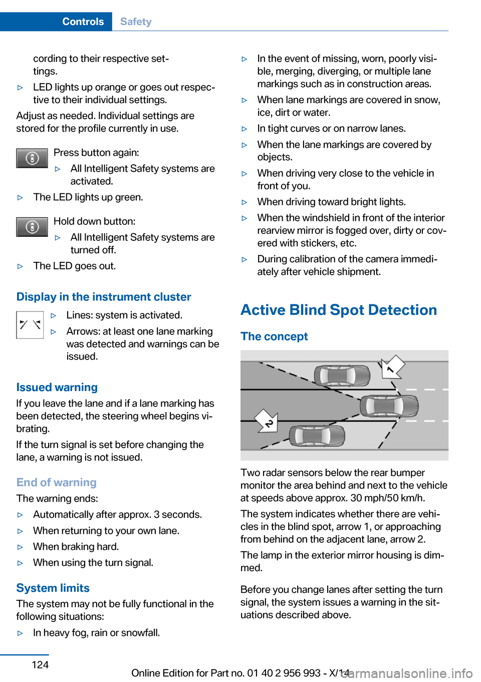
Two radar sensors below the rear bumper
monitor the area behind and next to the vehicle
at speeds above approx. 30 mph/50 km/h.
The system indicates whether there are vehi‐
cles in the blind spot, arrow 1, or approaching
from behind on the adjacent lane, arrow 2.
The lamp in the exterior mirror housing is dim‐
med.
Before you change lanes after setting the turn
signal, the system issues a warning in the sit‐
uations described above.
Seite 124ControlsSafety124
Online Edition for Part no. 01 40 2 956 993 - X/14
Page 143 of 251
A display appears as soon as Park Distance
Control (PDC) is activated.
The range of the sensors is represented in the
colors green, yellow and red.
When the image of the rearview camera is dis‐
played, the reel can be made to PDC:
"Rear view camera"
System limits
Limits of ultrasonic measurement
Ultrasonic measuring might not function under
the following circumstances:
▷For small children and animals.▷For persons with certain clothing, e.g.
coats.▷With external interference of the ultra‐
sound, e.g. from passing vehicles or loud
machines.▷When sensors are dirty, iced over, dam‐
aged or out of position.▷Under certain weather conditions such as
high relative humidity, rain, snowfall, ex‐
treme heat or strong wind.▷With tow bars and trailer couplings of other
vehicles.▷With thin or wedge-shaped objects.▷With moving objects.▷With elevated, protruding objects such as
ledges or cargo.▷With objects with corners and sharp edges.▷With objects with a fine surface structure
such as fences.▷For objects with porous surfaces.
Low objects already displayed, e.g., curbs, can
move into the blind area of the sensors before
or after a continuous tone sounds.
False warnings
PDC may issue a warning under the following
conditions even though there is no obstacle
within the detection range:▷In heavy rain.▷When sensors are very dirty or covered
with ice.▷When sensors are covered in snow.▷On rough road surfaces.▷On uneven surfaces, such as speed
bumps.▷In large buildings with right angles and
smooth walls, e.g., in underground ga‐
rages.▷Through heavy pollution.▷Due to other ultrasound sources, e.g.,
sweeping machines, high pressure steam
cleaners or neon lights.
Malfunction
A Check Control message is displayed.
The range of the sensors is shown as a shaded
area on the Control Display.
PDC has failed. Have the system checked.
To ensure full functionality:
▷Keep the sensors clean and free of ice.▷dimmedDo not put any stickers on sen‐
sors.▷When using high-pressure washers, do not
spray the sensors for long periods and
maintain a distance of at least 12 in/30 cm.
Surround View
The concept Surround View comprises various camera as‐
sistance systems that help the driver when
parking, maneuvering, and at complex exits
and intersections.
▷Rearview camera, refer to page 140Seite 139Driving comfortControls139
Online Edition for Part no. 01 40 2 956 993 - X/14
Page 153 of 251
▷If a maximum number of parking attempts
or the time taken for parking is exceeded.▷When switching to another function on the
Control Display.▷When the button is released.▷If the tailgate is open.▷If doors are open.▷When setting the parking brake.▷During acceleration.▷When braking.▷When unfastening the driver's safety belt.
A Check Control message is displayed.
Flashing display on the selector lever The actually engaged transmission position
can deviate from the selector lever position in
some situations after function interruption.
The display in the selector lever flashes.
Observe the display in the instrument cluster,
refer to page 80, in these cases.
Resume An interrupted parking procedure can be con‐
tinued if needed.
Follow the instructions on the Control Display
to do this.
System limits
No parking assistance
The parking assistant does not offer assis‐
tance in the following situations:
▷In tight curves.
Functional limitations
The system may not be fully functional in the
following situations:
▷On bumpy road surfaces such as gravel
roads.▷On slippery ground.▷On steep uphill or downhill grades.▷With accumulations of leaves/snow in the
parking space.
Limits of ultrasonic measurement
Ultrasonic measuring might not function under
the following circumstances:
▷For small children and animals.▷For persons with certain clothing, e.g.
coats.▷With external interference of the ultra‐
sound, e.g. from passing vehicles or loud
machines.▷When sensors are dirty, iced over, dam‐
aged or out of position.▷Under certain weather conditions such as
high relative humidity, rain, snowfall, ex‐
treme heat or strong wind.▷With tow bars and trailer couplings of other
vehicles.▷With thin or wedge-shaped objects.▷With moving objects.▷With elevated, protruding objects such as
ledges or cargo.▷With objects with corners and sharp edges.▷With objects with a fine surface structure
such as fences.▷For objects with porous surfaces.
Low objects already displayed, e.g., curbs, can
move into the blind area of the sensors before
or after a continuous tone sounds.
The parking assistant may identify parking
spaces that are not suitable for parking.
Malfunction
A Check Control message is displayed.
The parking assistant failed. Have the system
checked.
Seite 149Driving comfortControls149
Online Edition for Part no. 01 40 2 956 993 - X/14
Page 157 of 251
Residual heat
The heat stored in the engine is used to heat
the interior.
Functional requirement▷Up to 15 minutes after switching off the
engine.▷Warm engine.▷The battery is sufficiently charged.▷External temperature below 77 ℉/25 ℃.
The availability of the function is shown on the
display of the automatic climate control.
Switching on
1.Switch off the ignition.2. Press the right side of the button
on the driver's side.
The symbol appears on the automatic cli‐
mate Control Display.
The interior temperature, air volume and air
distribution can be adjusted with the ignition
switched on.
Switch off
At the lowest fan speed, press the left side of
the button on the driver's side.
The symbol on the display of the automatic
climate control flashes.
Switching the system on/off Switch off
▷Complete system: Press and hold the left button on
the driver's side until the control
clicks off.▷On the front passenger side:
Press and hold the left button on
the front passenger side.Switching on
Press any button except:▷Rear window defroster.▷Left side of Air volume button.▷Seat ventilation.▷If necessary, SYNC program.
Microfilter/activated-charcoal filter
The microfilter removes dust and pollen from
the incoming air.
The activated-charcoal filter removes gaseous
pollutants from the outside air that enters the
vehicle.
This combined filter should be replaced during
scheduled maintenance, refer to page 211, of
your vehicle.
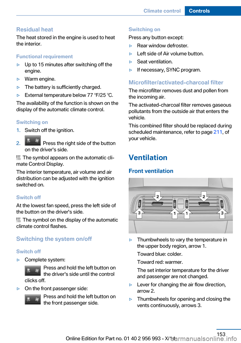
Ventilation Front ventilation
▷Thumbwheels to vary the temperature in
the upper body region, arrow 1.
Toward blue: colder.
Toward red: warmer.
The set interior temperature for the driver
and passenger are not changed.▷Lever for changing the air flow direction,
arrow 2.▷Thumbwheels for opening and closing the
vents continuously, arrows 3.Seite 153Climate controlControls153
Online Edition for Part no. 01 40 2 956 993 - X/14
Page 158 of 251
Adjusting the ventilation▷Ventilation for cooling:
Direct vent in your direction when vehicle's
interior is too hot.▷Draft-free ventilation:
Adjust the vent to let the air flow past you.
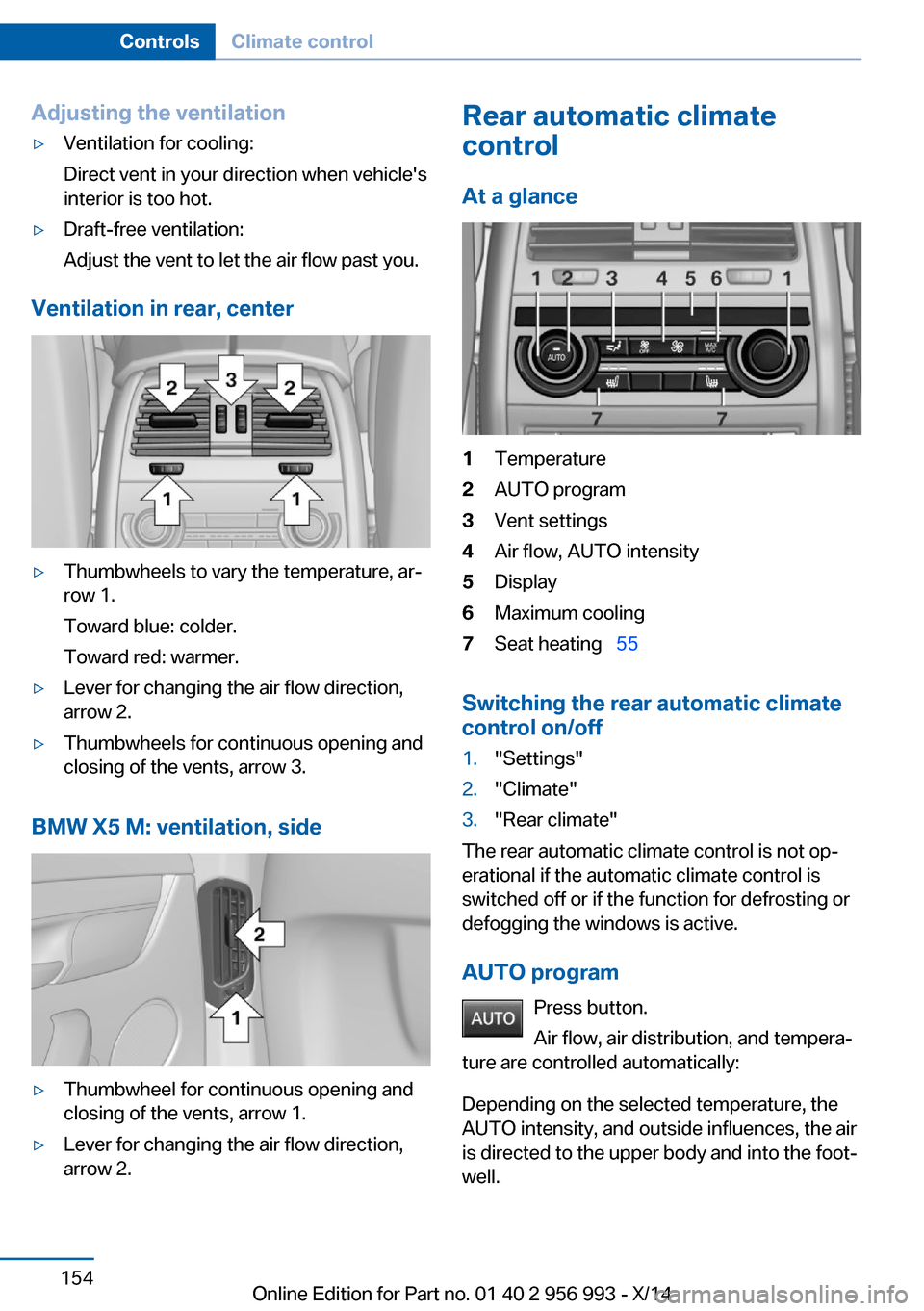
Ventilation in rear, center
▷Thumbwheels to vary the temperature, ar‐
row 1.
Toward blue: colder.
Toward red: warmer.▷Lever for changing the air flow direction,
arrow 2.▷Thumbwheels for continuous opening and
closing of the vents, arrow 3.
BMW X5 M: ventilation, side
▷Thumbwheel for continuous opening and
closing of the vents, arrow 1.▷Lever for changing the air flow direction,
arrow 2.Rear automatic climate
control
At a glance1Temperature2AUTO program3Vent settings4Air flow, AUTO intensity5Display6Maximum cooling7Seat heating 55
Switching the rear automatic climate
control on/off
1."Settings"2."Climate"3."Rear climate"
The rear automatic climate control is not op‐
erational if the automatic climate control is
switched off or if the function for defrosting or
defogging the windows is active.
AUTO program Press button.
Air flow, air distribution, and tempera‐
ture are controlled automatically:
Depending on the selected temperature, the
AUTO intensity, and outside influences, the air
is directed to the upper body and into the foot‐
well.
Seite 154ControlsClimate control154
Online Edition for Part no. 01 40 2 956 993 - X/14
Page 169 of 251
the stability of the child seat can be affected,
and there is an increased risk of injury because
of unexpected movement of the rear seat
backrest.◀
Ensure that the lock is securely engaged
When you fold back the backrest make
sure that it locks in place. When this happens
the red warning field on the seat disappears.
Otherwise transported cargo could shoot into
the car's interior during braking or evasive ma‐
neuvers and endanger occupants.◀
Using the middle safety belt
If the middle safety belt in the rear is
used, the larger side of the backrest must be
locked. Otherwise, the safety belt will not have
a restraining effect.◀
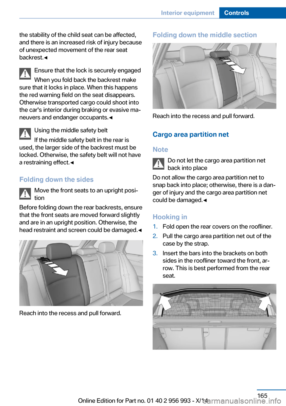
Folding down the sides Move the front seats to an upright posi‐
tion
Before folding down the rear backrests, ensure
that the front seats are moved forward slightly
and are in an upright position. Otherwise, the
head restraint and screen could be damaged.◀
Reach into the recess and pull forward.
Folding down the middle section
Reach into the recess and pull forward.
Cargo area partition net
Note Do not let the cargo area partition net
back into place
Do not allow the cargo area partition net to
snap back into place; otherwise, there is a dan‐
ger of injury and the cargo area partition net
could be damaged.◀
Hooking in
1.Fold open the rear covers on the roofliner.2.Pull the cargo area partition net out of the
case by the strap.3.Insert the bars into the brackets on both
sides in the roofliner toward the front, ar‐
row. This is best performed from the rear
seat.Seite 165Interior equipmentControls165
Online Edition for Part no. 01 40 2 956 993 - X/14