ignition BMW X5M 2014 F85 Owner's Guide
[x] Cancel search | Manufacturer: BMW, Model Year: 2014, Model line: X5M, Model: BMW X5M 2014 F85Pages: 251, PDF Size: 7.35 MB
Page 93 of 251
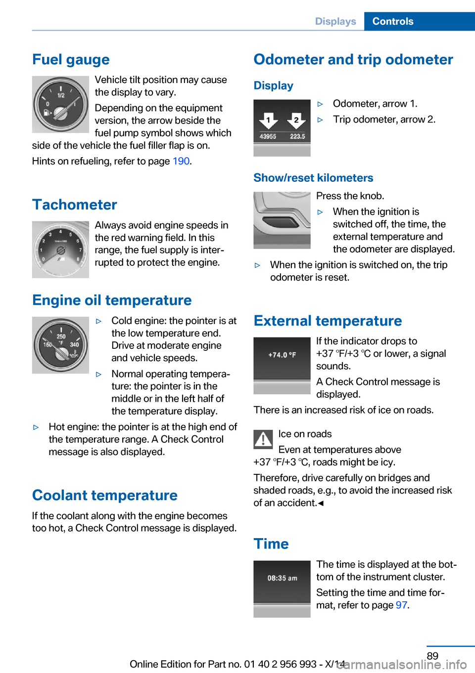
Fuel gaugeVehicle tilt position may cause
the display to vary.
Depending on the equipment
version, the arrow beside the
fuel pump symbol shows which
side of the vehicle the fuel filler flap is on.
Hints on refueling, refer to page 190.
Tachometer Always avoid engine speeds in
the red warning field. In this
range, the fuel supply is inter‐
rupted to protect the engine.
Engine oil temperature▷Cold engine: the pointer is at
the low temperature end.
Drive at moderate engine
and vehicle speeds.▷Normal operating tempera‐
ture: the pointer is in the
middle or in the left half of
the temperature display.▷Hot engine: the pointer is at the high end of
the temperature range. A Check Control
message is also displayed.
Coolant temperature
If the coolant along with the engine becomes
too hot, a Check Control message is displayed.
Odometer and trip odometer
Display▷Odometer, arrow 1.▷Trip odometer, arrow 2.
Show/reset kilometers Press the knob.
▷When the ignition is
switched off, the time, the
external temperature and
the odometer are displayed.▷When the ignition is switched on, the trip
odometer is reset.
External temperature
If the indicator drops to
+37 ℉/+3 ℃ or lower, a signal
sounds.
A Check Control message is displayed.
There is an increased risk of ice on roads.
Ice on roads
Even at temperatures above
+37 ℉/+3 ℃, roads might be icy.
Therefore, drive carefully on bridges and
shaded roads, e.g., to avoid the increased risk
of an accident.◀
Time The time is displayed at the bot‐
tom of the instrument cluster.
Setting the time and time for‐
mat, refer to page 97.
Seite 89DisplaysControls89
Online Edition for Part no. 01 40 2 956 993 - X/14
Page 96 of 251
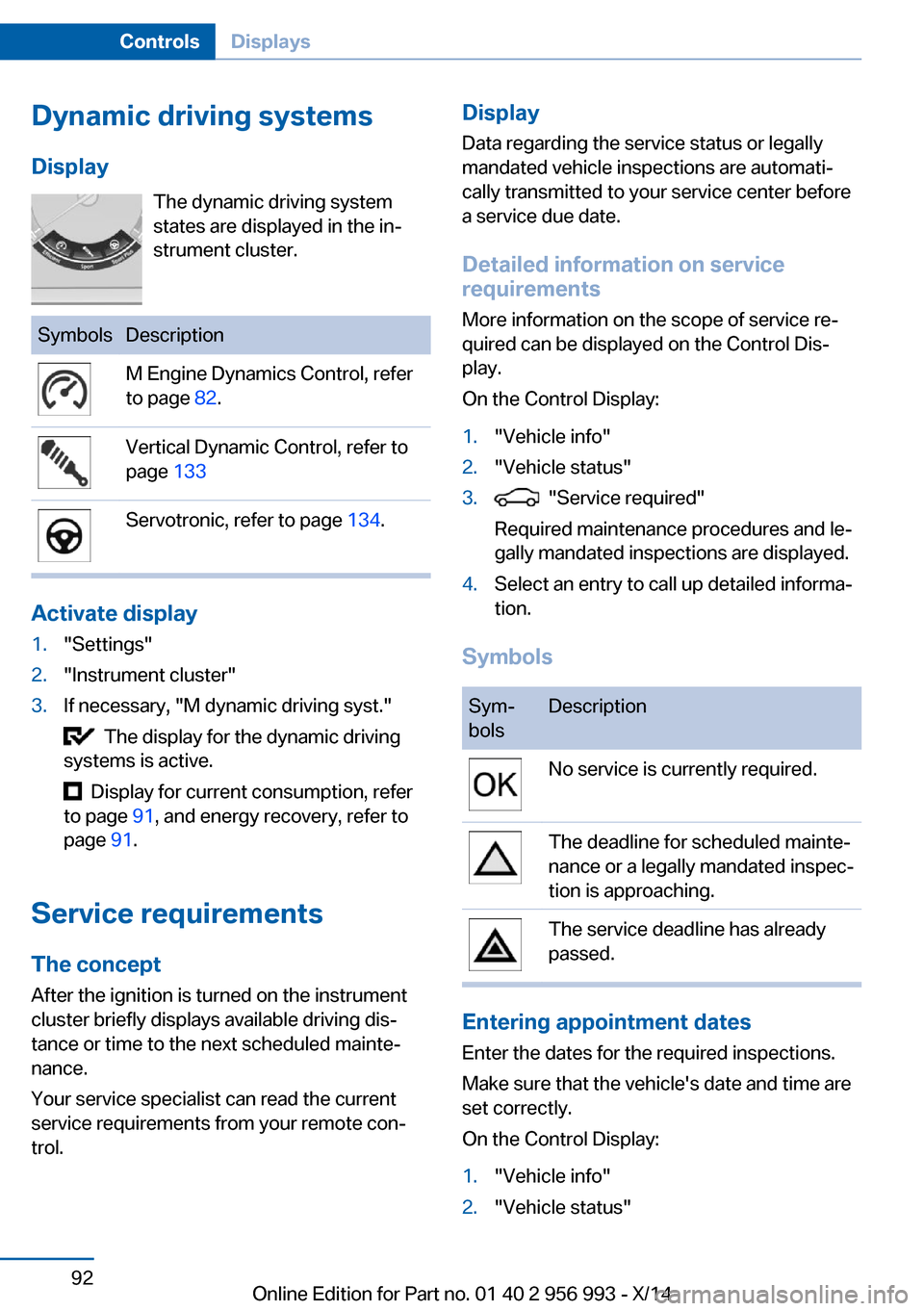
Dynamic driving systemsDisplay The dynamic driving system
states are displayed in the in‐
strument cluster.SymbolsDescriptionM Engine Dynamics Control, refer
to page 82.Vertical Dynamic Control, refer to
page 133Servotronic, refer to page 134.
Activate display
1."Settings"2."Instrument cluster"3.If necessary, "M dynamic driving syst."
The display for the dynamic driving
systems is active.
Display for current consumption, refer
to page 91, and energy recovery, refer to
page 91.
Service requirements
The concept After the ignition is turned on the instrument
cluster briefly displays available driving dis‐
tance or time to the next scheduled mainte‐
nance.
Your service specialist can read the current
service requirements from your remote con‐
trol.
Display
Data regarding the service status or legally
mandated vehicle inspections are automati‐
cally transmitted to your service center before
a service due date.
Detailed information on service
requirements
More information on the scope of service re‐
quired can be displayed on the Control Dis‐
play.
On the Control Display:1."Vehicle info"2."Vehicle status"3. "Service required"
Required maintenance procedures and le‐
gally mandated inspections are displayed.4.Select an entry to call up detailed informa‐
tion.
Symbols
Sym‐
bolsDescriptionNo service is currently required.The deadline for scheduled mainte‐
nance or a legally mandated inspec‐
tion is approaching.The service deadline has already
passed.
Entering appointment dates
Enter the dates for the required inspections.
Make sure that the vehicle's date and time are
set correctly.
On the Control Display:
1."Vehicle info"2."Vehicle status"Seite 92ControlsDisplays92
Online Edition for Part no. 01 40 2 956 993 - X/14
Page 104 of 251
3."Brightness"4.Turn the controller.
When the low beams are activated, the bright‐
ness of the Head-up Display can be addition‐
ally influenced using the instrument lighting.
Settings are stored for the profile currently in
use.
Adjusting the height
On the Control Display:
1."Settings"2."Head-Up Display"3."Height"4.Turn the controller.
Settings are stored for the profile currently in
use.
Setting the rotation
Only set the rotation while the vehicle is sta‐
tionary and the ignition is switched on.
On the Control Display:
1."Settings"2."Head-Up Display"3."Rotation"4.Turn the controller.
Settings are stored for the profile currently in
use.
Special windshield
The windshield is part of the system.
The shape of the windshield makes it possible
to display a precise image.
A film in the windshield prevents double im‐
ages from being displayed.
Therefore, have the special windshield re‐
placed by a service center only.
Shift Lights
General information The display is in the Head-up Display.
Shift Lights in the Head-up Display
Switching on Shift lights are only shown in the Head-up Dis‐
play in the M view, refer to page 99.1.Switch on Head-up Display, refer to
page 99.2."Settings"3."Head-Up Display"4."Displayed information"5."M View"
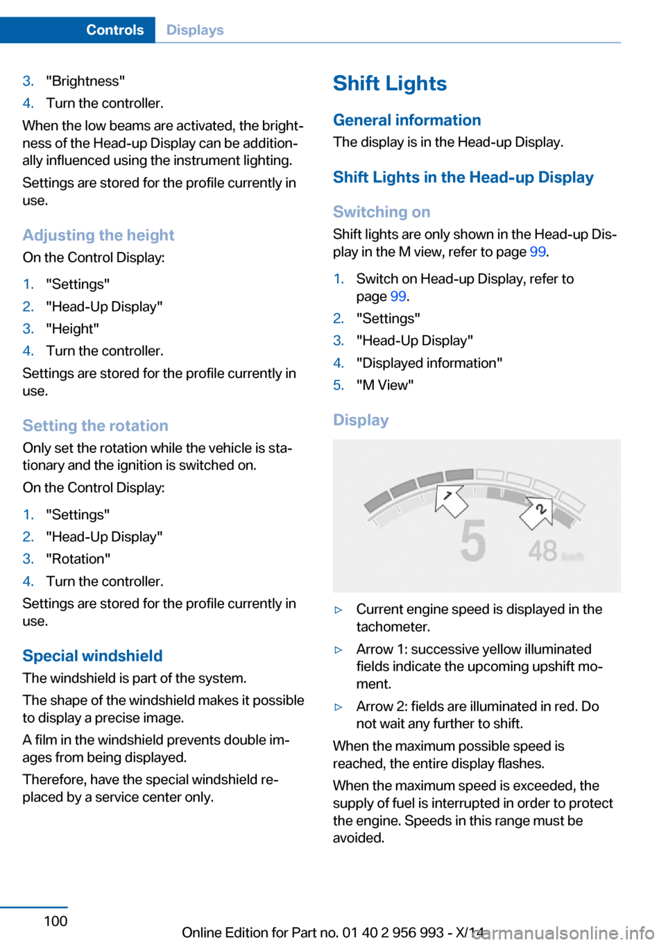
Display
▷Current engine speed is displayed in the
tachometer.▷Arrow 1: successive yellow illuminated
fields indicate the upcoming upshift mo‐
ment.▷Arrow 2: fields are illuminated in red. Do
not wait any further to shift.
When the maximum possible speed is
reached, the entire display flashes.
When the maximum speed is exceeded, the
supply of fuel is interrupted in order to protect
the engine. Speeds in this range must be
avoided.
Seite 100ControlsDisplays100
Online Edition for Part no. 01 40 2 956 993 - X/14
Page 105 of 251
LightsVehicle features and optionsThis chapter describes all standard, country-
specific and optional features offered with the
series. It also describes features that are not
necessarily available in your car, e. g., due to
the selected options or country versions. This
also applies to safety-related functions and
systems.
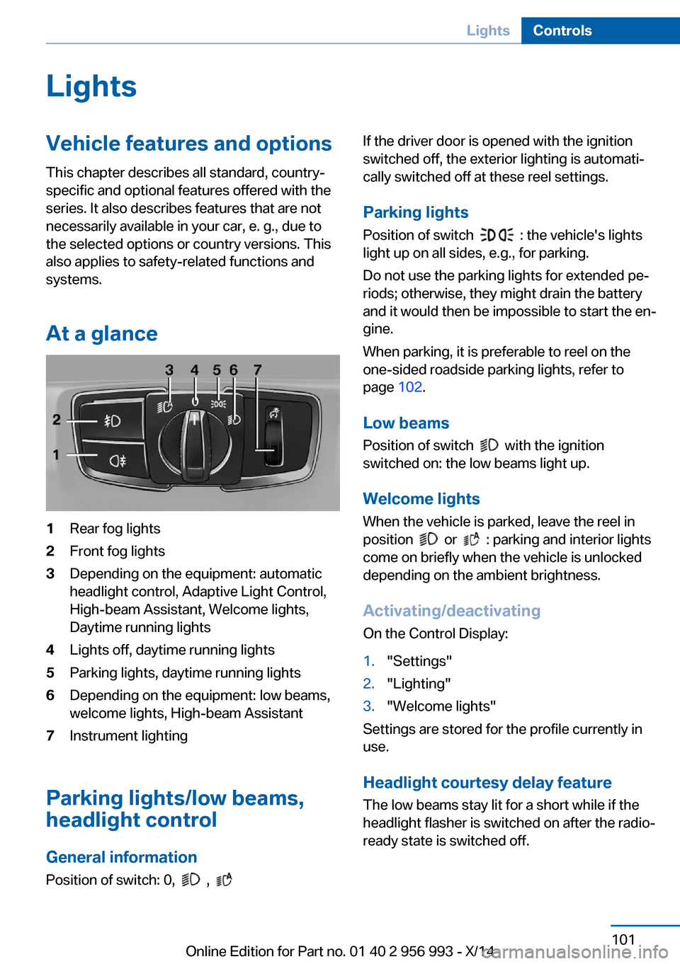
At a glance1Rear fog lights2Front fog lights3Depending on the equipment: automatic
headlight control, Adaptive Light Control,
High-beam Assistant, Welcome lights,
Daytime running lights4Lights off, daytime running lights5Parking lights, daytime running lights6Depending on the equipment: low beams,
welcome lights, High-beam Assistant7Instrument lighting
Parking lights/low beams,
headlight control
General information
Position of switch: 0,
,
If the driver door is opened with the ignition
switched off, the exterior lighting is automati‐
cally switched off at these reel settings.
Parking lights
Position of switch
: the vehicle's lights
light up on all sides, e.g., for parking.
Do not use the parking lights for extended pe‐
riods; otherwise, they might drain the battery
and it would then be impossible to start the en‐
gine.
When parking, it is preferable to reel on the
one-sided roadside parking lights, refer to
page 102.
Low beams Position of switch
with the ignition
switched on: the low beams light up.
Welcome lights
When the vehicle is parked, leave the reel in
position
or : parking and interior lights
come on briefly when the vehicle is unlocked
depending on the ambient brightness.
Activating/deactivating
On the Control Display:
1."Settings"2."Lighting"3."Welcome lights"
Settings are stored for the profile currently in
use.
Headlight courtesy delay featureThe low beams stay lit for a short while if the
headlight flasher is switched on after the radio-
ready state is switched off.
Seite 101LightsControls101
Online Edition for Part no. 01 40 2 956 993 - X/14
Page 106 of 251
Setting the durationOn the Control Display:1."Settings"2."Lighting"3."Pathway lighting:"4.Set length of time.
Settings are stored for the profile currently in
use.
Automatic headlight control
Position of switch
: the low beams are acti‐
vated and off automatically, e.g., in tunnels, in
twilight or if there is precipitation. The indicator
lamp in the instrument cluster lights up.
When emerging from a tunnel during the day,
the low beams are not switched off immedi‐
ately but instead only after approx. 2 minutes.
A blue sky with the sun low on the horizon can
cause the lights to be switched on.
The low beams always stay on when the fog
lights are activated.
Personal responsibility
The automatic headlight control cannot
serve as a substitute for your personal judg‐
ment in determining when to turn the lights on
in response to ambient lighting conditions.
E. g. the sensors are unable to detect fog or
hazy weather. To avoid safety risks under
these conditions, you should always switch on
the lights manually.◀
Daytime running lights With the ignition switched on, the daytime run‐
ning lights light up in position 0,
or .
After the ignition is switched off, the parking
lights light up in position
.
Activating/deactivating
In some countries, daytime running lights are
mandatory, so it may not be possible to deacti‐
vate the daytime running lights.
On the Control Display:1."Settings"2."Lighting"3."Daytime running lamps"
Settings are stored for the profile currently in
use.
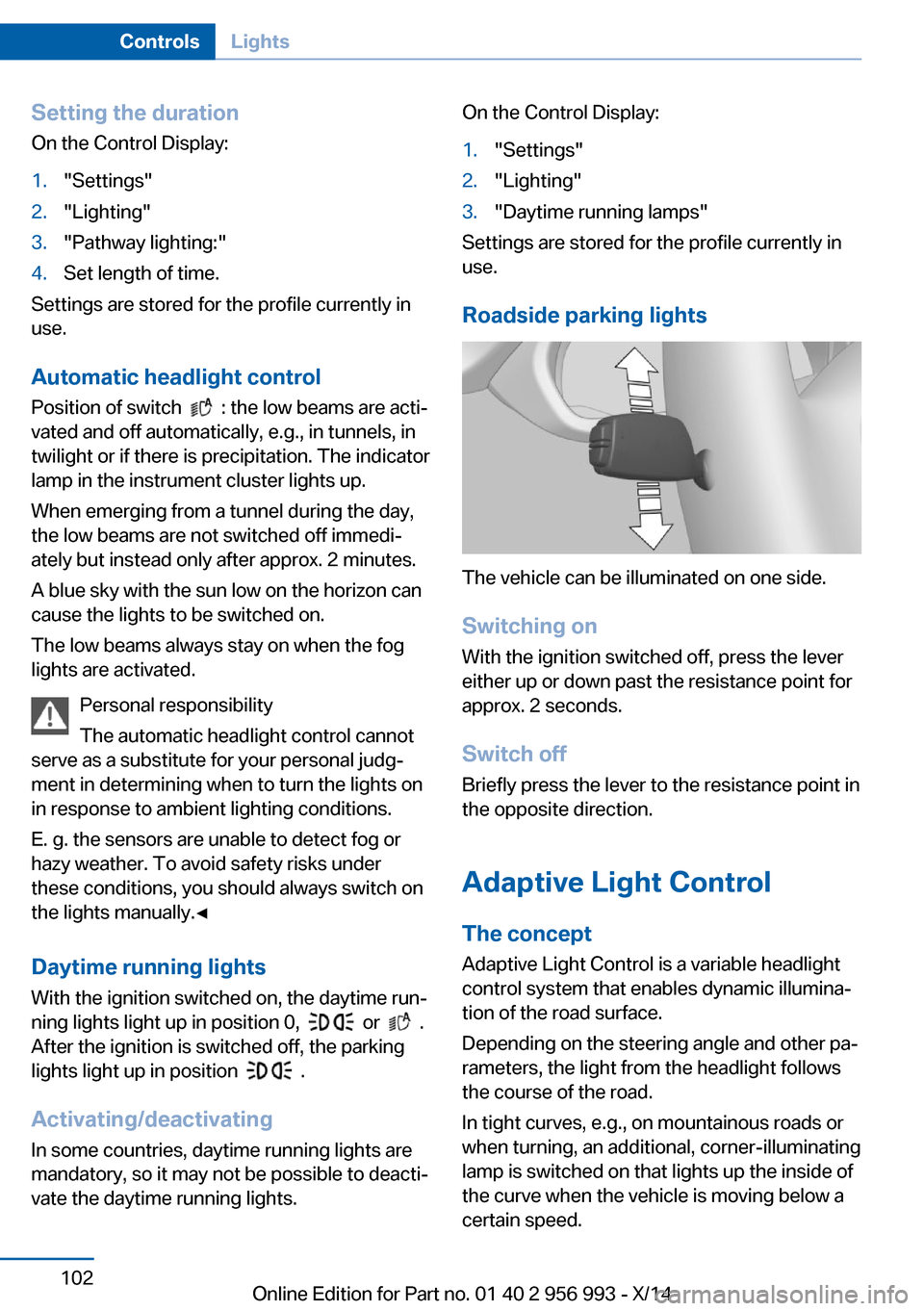
Roadside parking lights
The vehicle can be illuminated on one side.
Switching on With the ignition switched off, press the lever
either up or down past the resistance point for
approx. 2 seconds.
Switch off Briefly press the lever to the resistance point in
the opposite direction.
Adaptive Light Control The concept
Adaptive Light Control is a variable headlight
control system that enables dynamic illumina‐
tion of the road surface.
Depending on the steering angle and other pa‐ rameters, the light from the headlight follows
the course of the road.
In tight curves, e.g., on mountainous roads or
when turning, an additional, corner-illuminating
lamp is switched on that lights up the inside of
the curve when the vehicle is moving below a certain speed.
Seite 102ControlsLights102
Online Edition for Part no. 01 40 2 956 993 - X/14
Page 107 of 251
ActivatingPosition of switch
with the ignition
switched on.
To avoid blinding oncoming traffic, the Adap‐
tive Light Control does not swivel to the driv‐
er's side when the vehicle is at a standstill.
The turning lights are automatically switched
on depending on the steering angle or the use
of turn signals.
When driving in reverse, the turning lights may
be automatically switched on regardless of the
steering angle.
Self-leveling headlights The self-leveling headlights compensate for
acceleration and braking operations in order
not to blind the oncoming traffic and to achieve
optimum illumination of the roadway.
Malfunction A Check Control message is displayed.
Adaptive Light Control is malfunctioning or has
failed. Have the system checked as soon as
possible.
High-beam Assistant
The concept When the low beams are activated, this system
automatically switches the high beams on and
off or suppresses the light in the areas that
blind oncoming traffic. The procedure is con‐
trolled by a camera on the front of the interior
rearview mirror. The assistant ensures that the
high beams are activated whenever the traffic
situation allows. The driver can intervene at
any time and reel the high beams on and off as
usual.
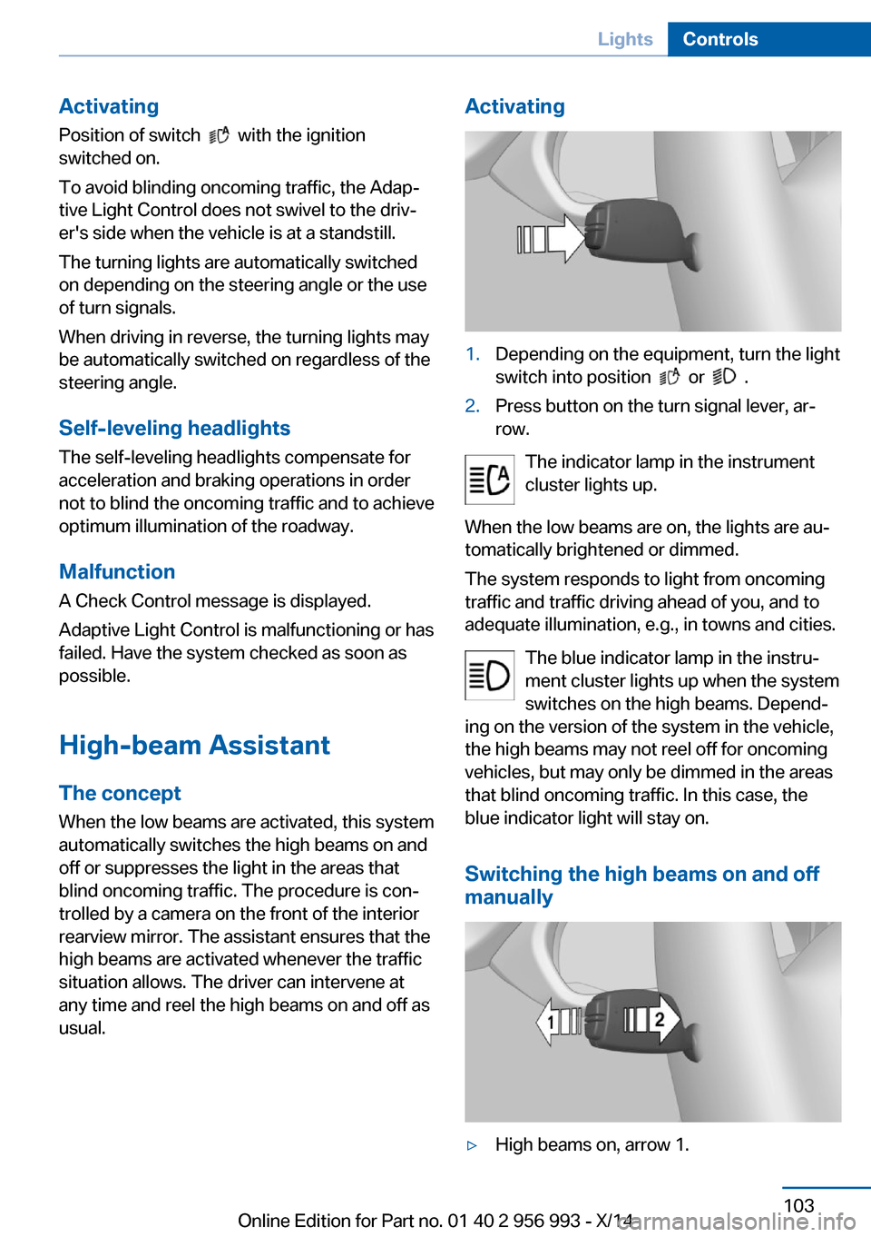
Activating1.Depending on the equipment, turn the light
switch into position
or .
2.Press button on the turn signal lever, ar‐
row.
The indicator lamp in the instrument
cluster lights up.
When the low beams are on, the lights are au‐
tomatically brightened or dimmed.
The system responds to light from oncoming
traffic and traffic driving ahead of you, and to
adequate illumination, e.g., in towns and cities.
The blue indicator lamp in the instru‐
ment cluster lights up when the system
switches on the high beams. Depend‐
ing on the version of the system in the vehicle, the high beams may not reel off for oncoming
vehicles, but may only be dimmed in the areas
that blind oncoming traffic. In this case, the blue indicator light will stay on.
Switching the high beams on and off manually
▷High beams on, arrow 1.Seite 103LightsControls103
Online Edition for Part no. 01 40 2 956 993 - X/14
Page 111 of 251
Protective action
Airbags are not triggered in every impact situa‐
tion, e.g., in less severe accidents or rear-end
collisions.
Information on how to ensure the optimal
protective effect of the airbags▷Keep at a distance from the airbags.▷Always grasp the steering wheel on the
steering wheel rim, holding your hands at
the 3 o'clock and 9 o'clock positions, to
keep the risk of injury to your hands or
arms as low as possible when the airbag is
triggered.▷There should be no person, animals, or ob‐
jects between an airbag and a person.▷Do not use the cover of the front airbag on
the front passenger side as a storage area.▷Dashboard and windshield on the front
passenger side must stay clear - do not at‐
tach adhesive labels or coverings and do
not attach brackets or cables, e. g., for GPS
devices or' mobile phones.▷Make sure that the front passenger is sit‐
ting correctly, i.e., keeps his or her feet and
legs in the footwell; otherwise, leg injuries
might occur when front airbag is activated.▷Do not place slip covers, seat cushions or
other objects on the front passenger seat
that are not approved specifically for seats
with integrated side airbags.▷Do not hang pieces of clothing, such as
jackets, over the backrests.▷Make sure that occupants keep their heads
away from the side airbag and do not rest
against the head airbag; otherwise, injuries
might occur when airbag is activated.▷Do not remove the airbag system.▷Do not remove the steering wheel.▷Do not apply adhesive materials to the air‐
bag cover panels, do not cover them or
modify them in any way.▷Never modify either the individual compo‐
nents or the wiring in the airbag system.
This also applies to steering wheel covers,
the dashboard, the seats, the roof pillars
and the sides of the roofliner.◀
Even when you follow all instructions very
closely, injury from contact with the airbags
cannot be ruled out in certain situations.
The ignition and inflation noise may lead to
short-term and, in most cases, temporary
hearing impairment in sensitive individuals.
Malfunction, deactivation and after de‐
ploying the airbags
Do not touch the individual components imme‐
diately after the system has been triggered;
otherwise, you may risk burns.
Only have the airbags checked, repaired or dis‐
mantled and the airbag generator scrapped by
the service center or an authorized repair shop
for handling explosives.
Non-professional attempts to service the sys‐
tem could lead to failure in an emergency or
unintentional activation of the airbag - both
may lead to injury.◀
Warnings and information on the airbags are also found on the sun visors.
Functional readiness of the airbag
system
When the ignition is reel on, the warn‐
ing lamp in the instrument cluster lights
up briefly and thereby indicates the op‐
erational readiness of the entire airbag system
and the belt tensioner.
Airbag system malfunctioning
▷Warning lamp does not come on when the
ignition is turned on.▷The warning lamp lights up continuously.Seite 107SafetyControls107
Online Edition for Part no. 01 40 2 956 993 - X/14
Page 157 of 251
Residual heat
The heat stored in the engine is used to heat
the interior.
Functional requirement▷Up to 15 minutes after switching off the
engine.▷Warm engine.▷The battery is sufficiently charged.▷External temperature below 77 ℉/25 ℃.
The availability of the function is shown on the
display of the automatic climate control.
Switching on
1.Switch off the ignition.2. Press the right side of the button
on the driver's side.
The symbol appears on the automatic cli‐
mate Control Display.
The interior temperature, air volume and air
distribution can be adjusted with the ignition
switched on.
Switch off
At the lowest fan speed, press the left side of
the button on the driver's side.
The symbol on the display of the automatic
climate control flashes.
Switching the system on/off Switch off
▷Complete system: Press and hold the left button on
the driver's side until the control
clicks off.▷On the front passenger side:
Press and hold the left button on
the front passenger side.Switching on
Press any button except:▷Rear window defroster.▷Left side of Air volume button.▷Seat ventilation.▷If necessary, SYNC program.
Microfilter/activated-charcoal filter
The microfilter removes dust and pollen from
the incoming air.
The activated-charcoal filter removes gaseous
pollutants from the outside air that enters the
vehicle.
This combined filter should be replaced during
scheduled maintenance, refer to page 211, of
your vehicle.
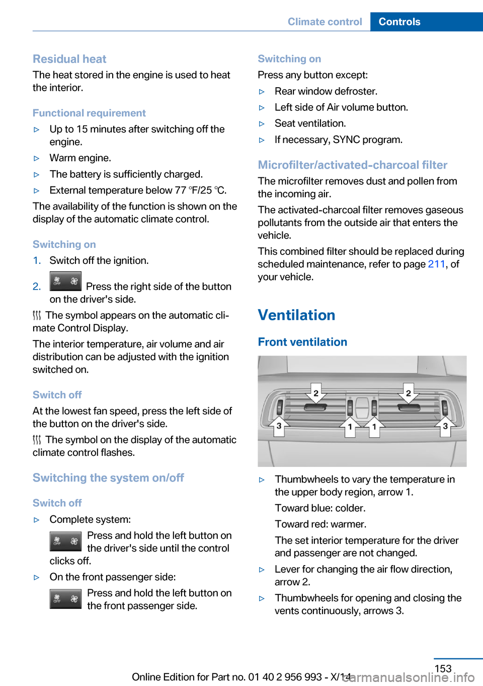
Ventilation Front ventilation
▷Thumbwheels to vary the temperature in
the upper body region, arrow 1.
Toward blue: colder.
Toward red: warmer.
The set interior temperature for the driver
and passenger are not changed.▷Lever for changing the air flow direction,
arrow 2.▷Thumbwheels for opening and closing the
vents continuously, arrows 3.Seite 153Climate controlControls153
Online Edition for Part no. 01 40 2 956 993 - X/14
Page 161 of 251
Interior equipmentVehicle features and optionsThis chapter describes all standard, country-
specific and optional features offered with the
series. It also describes features that are not
necessarily available in your car, e. g., due to
the selected options or country versions. This
also applies to safety-related functions and
systems.
Universal Integrated RemoteControl
The concept
The universal garage door opener can operate
up to 3 functions of remote-controlled sys‐
tems such as garage door drives or lighting
systems. The universal garage door opener re‐
places up to 3 different hand-held transmitters.
To operate the remote control, the buttons on
the interior rearview mirror must be program‐
med with the desired functions. The hand-held
transmitter for the particular system is required
in order to program the remote control.
During programming
During programming and before activat‐
ing a device using the universal garage door
opener, ensure that there are no people, ani‐
mals or objects in the area of the remote-con‐
trolled device; otherwise, there is a risk of in‐
jury or damage.
Also follow the safety instructions of the hand-
held transmitter.◀
Before selling the vehicle, delete the stored
functions for the sake of security.
Compatibility If this symbol is printed on the packag‐
ing or in the instructions of the system
to be controlled, the system is gener‐ally compatible with the universal garage door
opener.
If you have any questions, please contact:▷Your service center.▷www.homelink.com on the Internet.
HomeLink is a registered trademark of Gentex
Corporation.
Control elements on the interior
rearview mirror
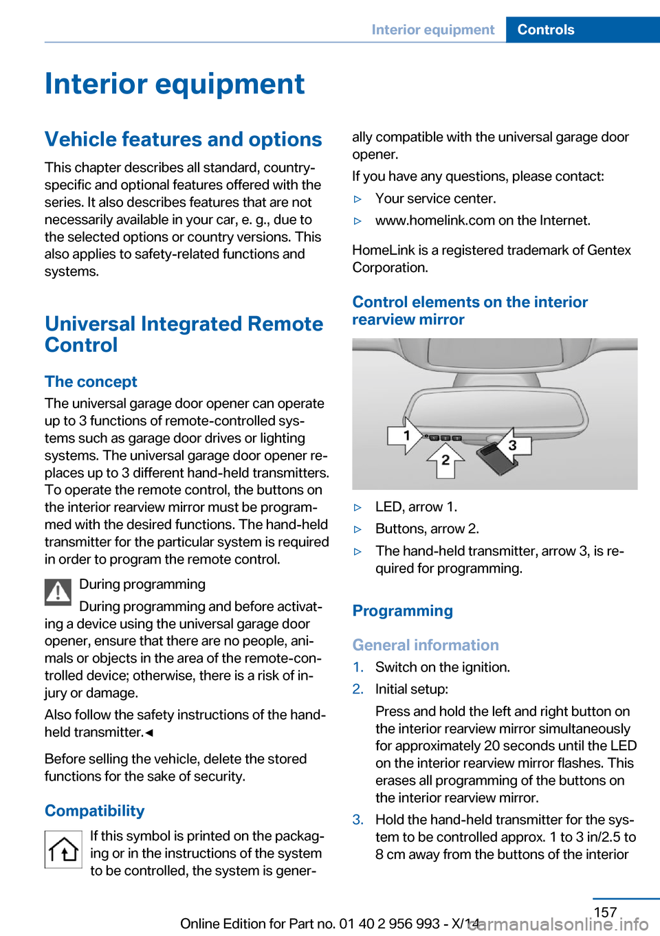
▷LED, arrow 1.▷Buttons, arrow 2.▷The hand-held transmitter, arrow 3, is re‐
quired for programming.
Programming
General information
1.Switch on the ignition.2.Initial setup:
Press and hold the left and right button on
the interior rearview mirror simultaneously
for approximately 20 seconds until the LED
on the interior rearview mirror flashes. This
erases all programming of the buttons on
the interior rearview mirror.3.Hold the hand-held transmitter for the sys‐
tem to be controlled approx. 1 to 3 in/2.5 to
8 cm away from the buttons of the interiorSeite 157Interior equipmentControls157
Online Edition for Part no. 01 40 2 956 993 - X/14
Page 162 of 251
rearview mirror. The required distance de‐
pends on the manual transmitter.4.Simultaneously press and hold the button
of the desired function on the hand-held
transmitter and the button to be program‐
med on the interior rearview mirror. The
LED on the interior rearview mirror will be‐
gin flashing slowly.5.Release both buttons as soon as the LED
flashes more rapidly. The LED flashing
faster indicates that the button on the inte‐
rior rearview mirror has been programmed.
If the LED does not flash faster after at
least 60 seconds, change the distance be‐
tween the interior rearview mirror and the
hand-held transmitter and repeat the step.
Several more attempts at different distan‐
ces may be necessary. Wait at least
15 seconds between attempts.
Canada: if programming with the hand-
held transmitter was interrupted, hold
down the interior rearview mirror button
and repeatedly press and release the
hand-held transmitter button for 2 sec‐
onds.6.To program other functions on other but‐
tons, repeat steps 3 to 5.
The systems can be controlled using the inte‐
rior rearview mirror buttons.
Special feature of the alternating-
code wireless system
If you are unable to operate the system after
repeated programming, please check if the
system to be controlled features an alternat‐
ing-code system.
Read the system's operating manual, or press
the programmed button on the interior rear‐
view mirror longer. If the LED on the interior
rearview mirror starts flashing rapidly and then
stays lit constantly for 2 seconds, the system
features an alternating-code system. Flashing
and continuous illumination of the LED will re‐
peat for approximately 20 seconds.
For systems with an alternating-code system,
the universal garage door opener and the sys‐
tem also have to be synchronized.
Please read the operating manual to find out how to synchronize the system.
Synchronizing is easier with the aid of a sec‐
ond person.
To synchronize:1.Park the vehicle within range of the re‐
mote-controlled system.2.Program the relevant button on the interior
rearview mirror as described.3.Locate and press the synchronizing button
on the system being programmed. You
have approx. 30 seconds for the next step.4.Hold down the programmed button on the
interior rearview mirror for approximately
3 seconds and then release it. If necessary,
repeat this step up to three times in order
to finish synchronization. Once synchroni‐
zation is complete, the programmed func‐
tion will be carried out.
Reprogramming individual buttons
1.Switch on the ignition.2.Press and hold the interior rearview mirror
button to be programmed.3.As soon as the interior rearview mirror LED
starts flashing slowly, hold the hand-held
transmitter for the system to be controlled
approx. 1 to 3 in/2.5 to 8 cm away from the
buttons of the interior rearview mirror. The
required distance depends on the manual
transmitter.4.Likewise, press and hold the button of the
desired function on the hand-held trans‐
mitter.5.Release both buttons as soon as the inte‐
rior rearview mirror LED flashes more rap‐
idly. The LED flashing faster indicates that
the button on the interior rearview mirror
has been programmed. The system canSeite 158ControlsInterior equipment158
Online Edition for Part no. 01 40 2 956 993 - X/14