tire BMW X5M 2015 F85 Owner's Manual
[x] Cancel search | Manufacturer: BMW, Model Year: 2015, Model line: X5M, Model: BMW X5M 2015 F85Pages: 255, PDF Size: 6.73 MB
Page 5 of 255
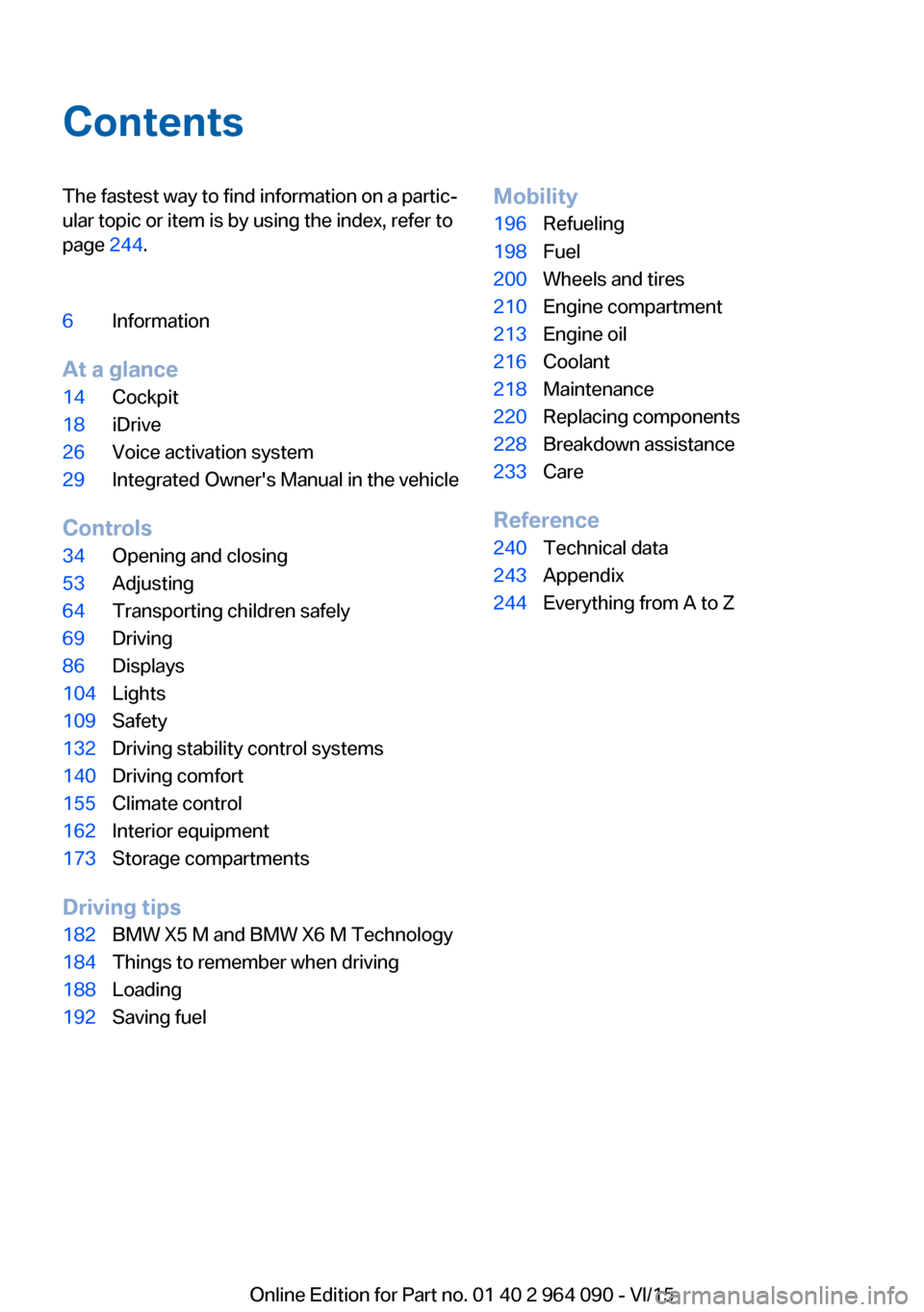
ContentsThe fastest way to find information on a partic‐
ular topic or item is by using the index, refer to
page 244.6Information
At a glance
14Cockpit18iDrive26Voice activation system29Integrated Owner's Manual in the vehicle
Controls
34Opening and closing53Adjusting64Transporting children safely69Driving86Displays104Lights109Safety132Driving stability control systems140Driving comfort155Climate control162Interior equipment173Storage compartments
Driving tips
182BMW X5 M and BMW X6 M Technology184Things to remember when driving188Loading192Saving fuelMobility196Refueling198Fuel200Wheels and tires210Engine compartment213Engine oil216Coolant218Maintenance220Replacing components228Breakdown assistance233Care
Reference
240Technical data243Appendix244Everything from A to Z
Online Edition for Part no. 01 40 2 964 090 - VI/15
Page 46 of 255
▷Interference of the radio connection from
transmission towers or other equipment
with high transmit power.▷Shielding of the remote control due to
metal objects.▷Interference of the radio connection from
mobile phones or other electronic devices
in direct proximity.
Do not transport the remote control together
with metal objects or electronic devices.
In the case of a malfunction, unlock and lock
the vehicle using the buttons of the remote
control or using the integrated key, refer to
page 39.
Adjusting
Unlocking The settings are saved in the active profile, re‐
fer to page 35.
Doors
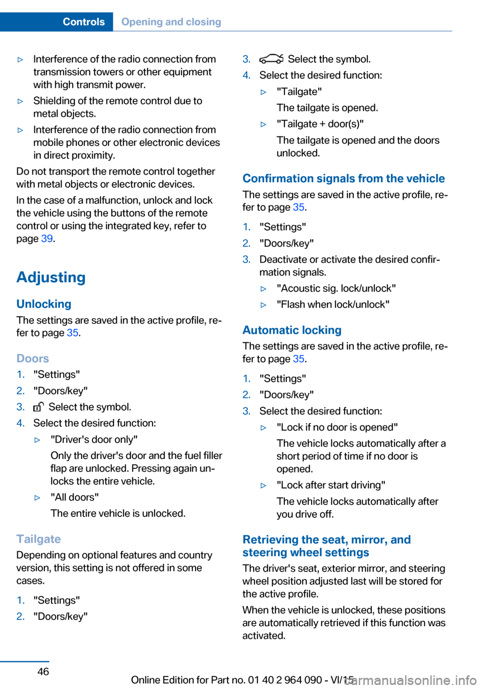
1."Settings"2."Doors/key"3. Select the symbol.4.Select the desired function:▷"Driver's door only"
Only the driver's door and the fuel filler
flap are unlocked. Pressing again un‐
locks the entire vehicle.▷"All doors"
The entire vehicle is unlocked.
Tailgate
Depending on optional features and country
version, this setting is not offered in some
cases.
1."Settings"2."Doors/key"3. Select the symbol.4.Select the desired function:▷"Tailgate"
The tailgate is opened.▷"Tailgate + door(s)"
The tailgate is opened and the doors
unlocked.
Confirmation signals from the vehicle
The settings are saved in the active profile, re‐
fer to page 35.
1."Settings"2."Doors/key"3.Deactivate or activate the desired confir‐
mation signals.▷"Acoustic sig. lock/unlock"▷"Flash when lock/unlock"
Automatic locking
The settings are saved in the active profile, re‐fer to page 35.
1."Settings"2."Doors/key"3.Select the desired function:▷"Lock if no door is opened"
The vehicle locks automatically after a
short period of time if no door is
opened.▷"Lock after start driving"
The vehicle locks automatically after
you drive off.
Retrieving the seat, mirror, and
steering wheel settings
The driver's seat, exterior mirror, and steering
wheel position adjusted last will be stored for
the active profile.
When the vehicle is unlocked, these positions
are automatically retrieved if this function was
activated.
Seite 46ControlsOpening and closing46
Online Edition for Part no. 01 40 2 964 090 - VI/15
Page 88 of 255
Flashing: acute warning of the imminent dan‐
ger of a collision when the vehicle approaches
another vehicle at a relatively high differential
speed.
Intervention by braking or make an evasive ma‐
neuver.
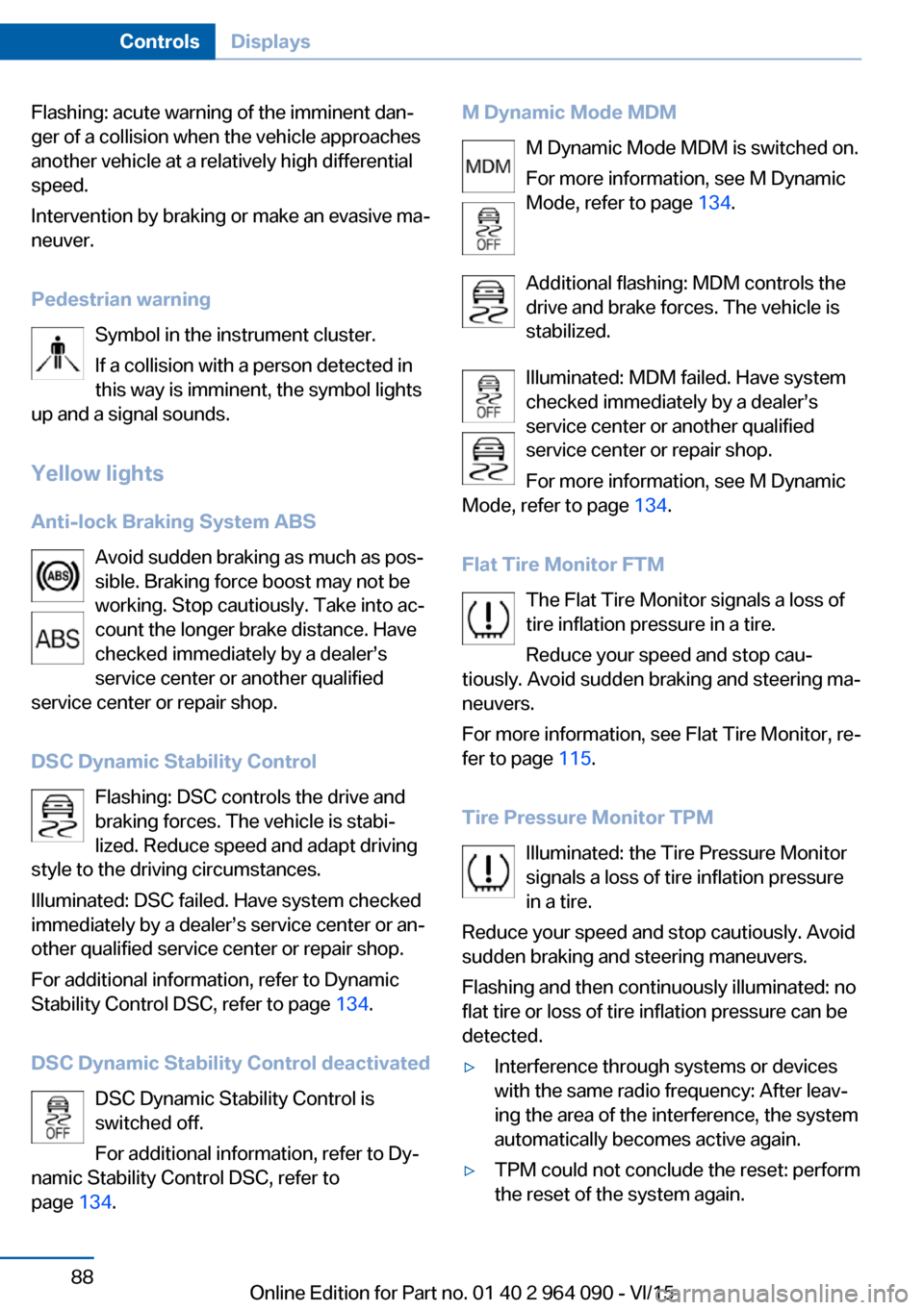
Pedestrian warning Symbol in the instrument cluster.
If a collision with a person detected in
this way is imminent, the symbol lights
up and a signal sounds.
Yellow lights
Anti-lock Braking System ABS Avoid sudden braking as much as pos‐
sible. Braking force boost may not be
working. Stop cautiously. Take into ac‐
count the longer brake distance. Have
checked immediately by a dealer’s
service center or another qualified
service center or repair shop.
DSC Dynamic Stability Control Flashing: DSC controls the drive and
braking forces. The vehicle is stabi‐
lized. Reduce speed and adapt driving
style to the driving circumstances.
Illuminated: DSC failed. Have system checked
immediately by a dealer’s service center or an‐
other qualified service center or repair shop.
For additional information, refer to Dynamic
Stability Control DSC, refer to page 134.
DSC Dynamic Stability Control deactivated DSC Dynamic Stability Control is
switched off.
For additional information, refer to Dy‐
namic Stability Control DSC, refer to
page 134.M Dynamic Mode MDM
M Dynamic Mode MDM is switched on.
For more information, see M Dynamic
Mode, refer to page 134.
Additional flashing: MDM controls the
drive and brake forces. The vehicle is
stabilized.
Illuminated: MDM failed. Have system
checked immediately by a dealer’s
service center or another qualified
service center or repair shop.
For more information, see M Dynamic
Mode, refer to page 134.
Flat Tire Monitor FTM The Flat Tire Monitor signals a loss of
tire inflation pressure in a tire.
Reduce your speed and stop cau‐
tiously. Avoid sudden braking and steering ma‐
neuvers.
For more information, see Flat Tire Monitor, re‐
fer to page 115.
Tire Pressure Monitor TPM Illuminated: the Tire Pressure Monitor
signals a loss of tire inflation pressure
in a tire.
Reduce your speed and stop cautiously. Avoid
sudden braking and steering maneuvers.
Flashing and then continuously illuminated: no
flat tire or loss of tire inflation pressure can be
detected.▷Interference through systems or devices
with the same radio frequency: After leav‐
ing the area of the interference, the system
automatically becomes active again.▷TPM could not conclude the reset: perform
the reset of the system again.Seite 88ControlsDisplays88
Online Edition for Part no. 01 40 2 964 090 - VI/15
Page 89 of 255
▷A wheel without TPM electronics is
mounted: Have it checked by a dealer’s
service center or another qualified service
center or repair shop as needed.▷Malfunction: Have system checked imme‐
diately by a dealer’s service center or an‐
other qualified service center or repair
shop.
For more information, see Tire Pressure Moni‐
tor, refer to page 112.
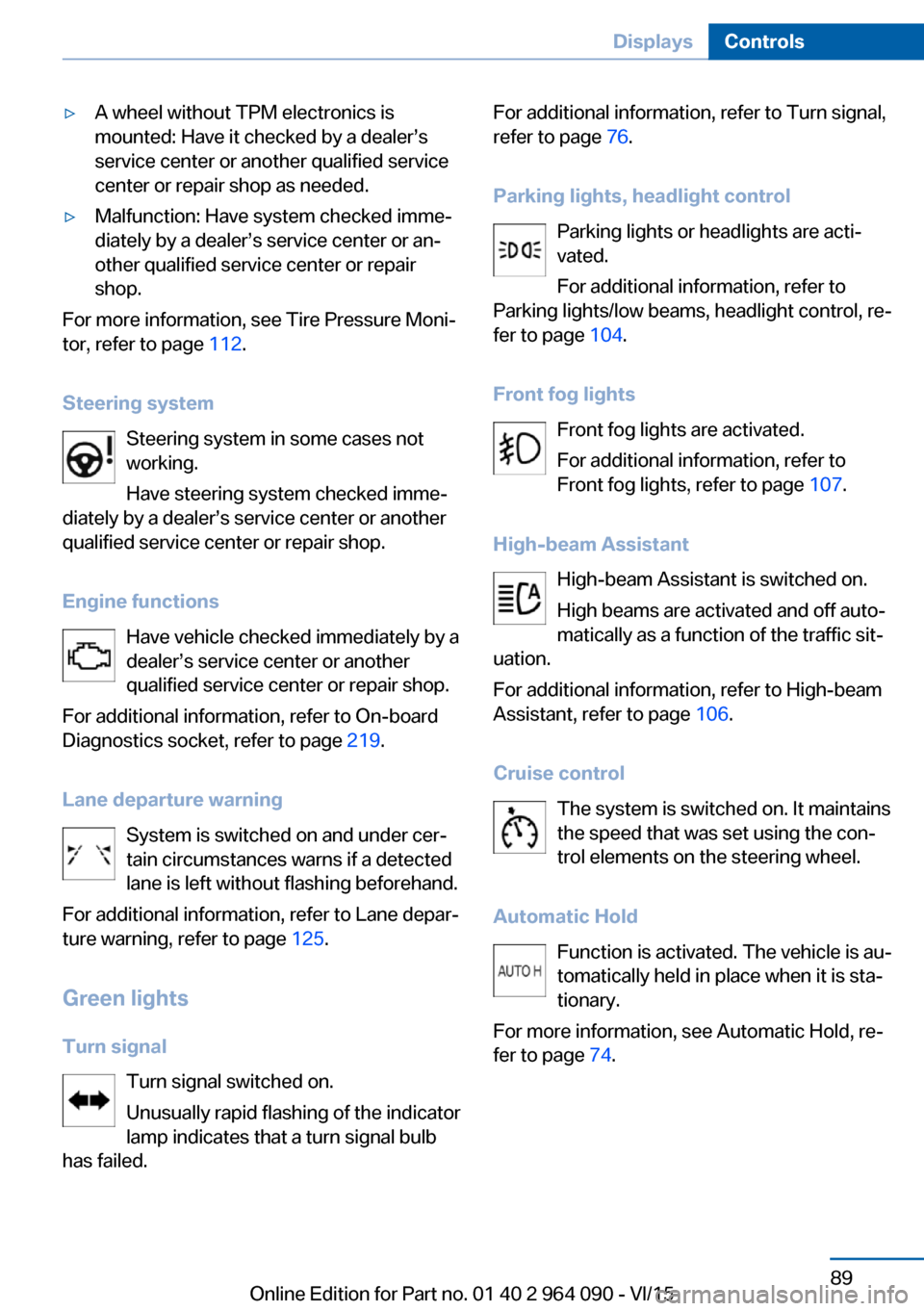
Steering system Steering system in some cases not
working.
Have steering system checked imme‐
diately by a dealer’s service center or another
qualified service center or repair shop.
Engine functions Have vehicle checked immediately by a
dealer’s service center or another
qualified service center or repair shop.
For additional information, refer to On-board
Diagnostics socket, refer to page 219.
Lane departure warning System is switched on and under cer‐
tain circumstances warns if a detected
lane is left without flashing beforehand.
For additional information, refer to Lane depar‐
ture warning, refer to page 125.
Green lights Turn signal Turn signal switched on.
Unusually rapid flashing of the indicator
lamp indicates that a turn signal bulb
has failed.
For additional information, refer to Turn signal,
refer to page 76.
Parking lights, headlight control Parking lights or headlights are acti‐
vated.
For additional information, refer to
Parking lights/low beams, headlight control, re‐
fer to page 104.
Front fog lights Front fog lights are activated.
For additional information, refer to
Front fog lights, refer to page 107.
High-beam Assistant High-beam Assistant is switched on.
High beams are activated and off auto‐
matically as a function of the traffic sit‐
uation.
For additional information, refer to High-beam
Assistant, refer to page 106.
Cruise control The system is switched on. It maintains
the speed that was set using the con‐
trol elements on the steering wheel.
Automatic Hold Function is activated. The vehicle is au‐
tomatically held in place when it is sta‐
tionary.
For more information, see Automatic Hold, re‐
fer to page 74.Seite 89DisplaysControls89
Online Edition for Part no. 01 40 2 964 090 - VI/15
Page 103 of 255
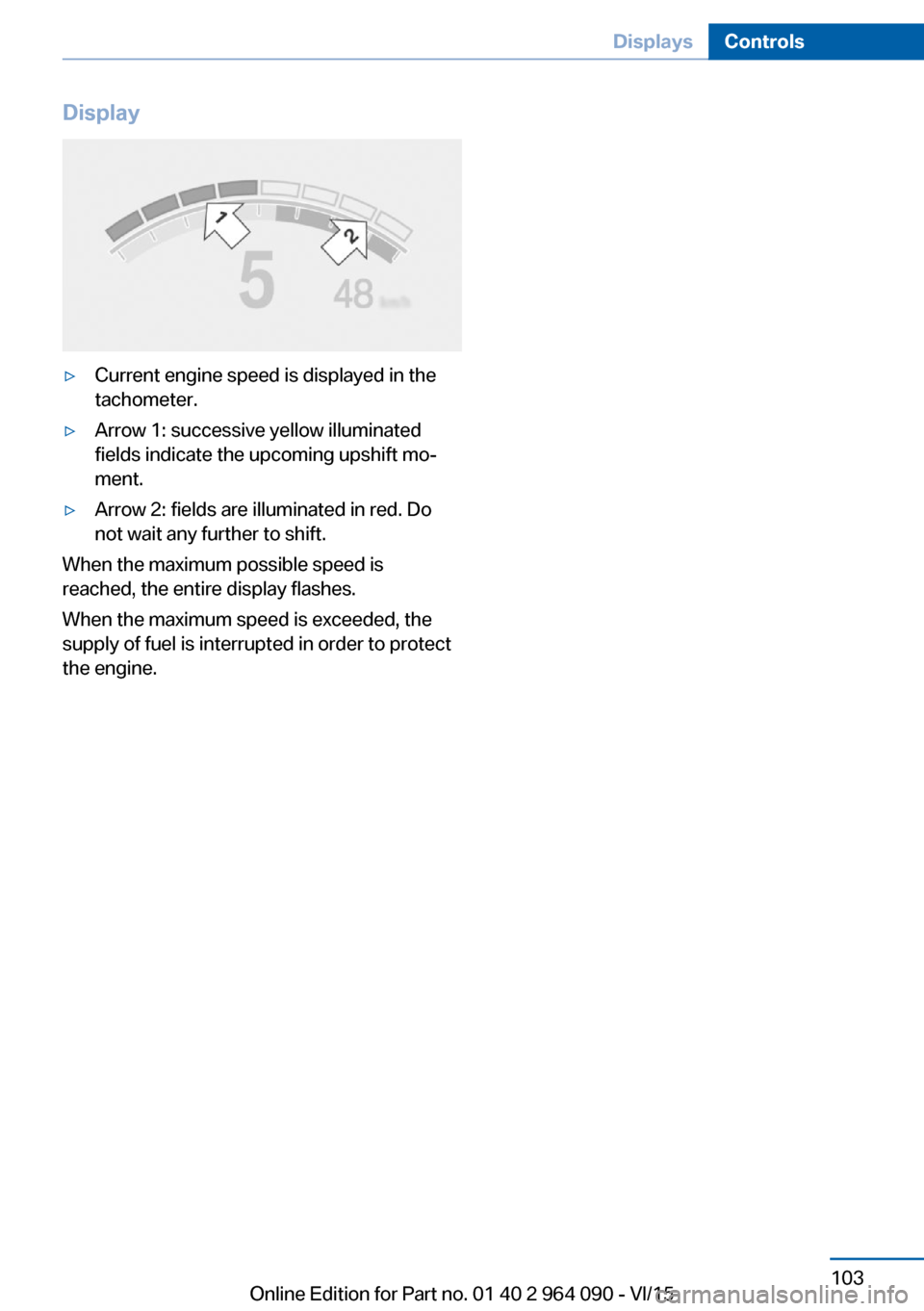
Display▷Current engine speed is displayed in the
tachometer.▷Arrow 1: successive yellow illuminated
fields indicate the upcoming upshift mo‐
ment.▷Arrow 2: fields are illuminated in red. Do
not wait any further to shift.
When the maximum possible speed is
reached, the entire display flashes.
When the maximum speed is exceeded, the
supply of fuel is interrupted in order to protect
the engine.
Seite 103DisplaysControls103
Online Edition for Part no. 01 40 2 964 090 - VI/15
Page 111 of 255
Correct functionWhen the ignition is switched on, the
warning lamp in the instrument cluster lights up briefly and thereby indicates
the operational readiness of the entire airbag
system and the belt tensioner.
Airbag system malfunctioning▷Warning lamp does not come on when the
ignition is turned on.▷The warning lamp lights up continuously.
Automatic deactivation of the front-
seat passenger airbags
The concept The system reads if the front passenger seat is
occupied by measuring the human body's re‐
sistance.
Front, knee and side airbag on the front pas‐
senger's side are either activated or deacti‐
vated.
Information Before transporting a child on the front pas‐
senger seat, refer to the safety notes and in‐
structions for children on the front passenger
seat, see Children.
WARNING
The ensure the front-seat passenger air‐
bag function, it must be detected, whether a
person occupies the front passenger seat. The
entire seat cushion area must be used for this
purpose. There is risk of injuries or danger to
life. Make sure that the front passenger keeps
his or her feet in the floor area.◀
Malfunction of the automatic
deactivation system
When transporting older children and adults,
the front-seat passenger airbags may be deac‐
tivated in certain sitting positions. In this case,
the indicator lamp for the front-seat passenger
airbags lights up.
In this case, change the sitting position so that
the front-seat passenger airbags are activated
and the indicator lamp goes out.
If it is not possible to activate the airbags, have
the person sit in the rear.
To enable correct recognition of the occupied
seat cushion▷Do not attach covers, cushions, ball mats
or other items to the front passenger seat
unless they are specifically determined to
be safe for use on the front passenger
seat.▷Do not place any electronic devices on the
passenger seat if a child restraint system is
to be installed on it.▷Do not place objects under the seat that
could press against the seat from below.▷No moisture in or on the seat.
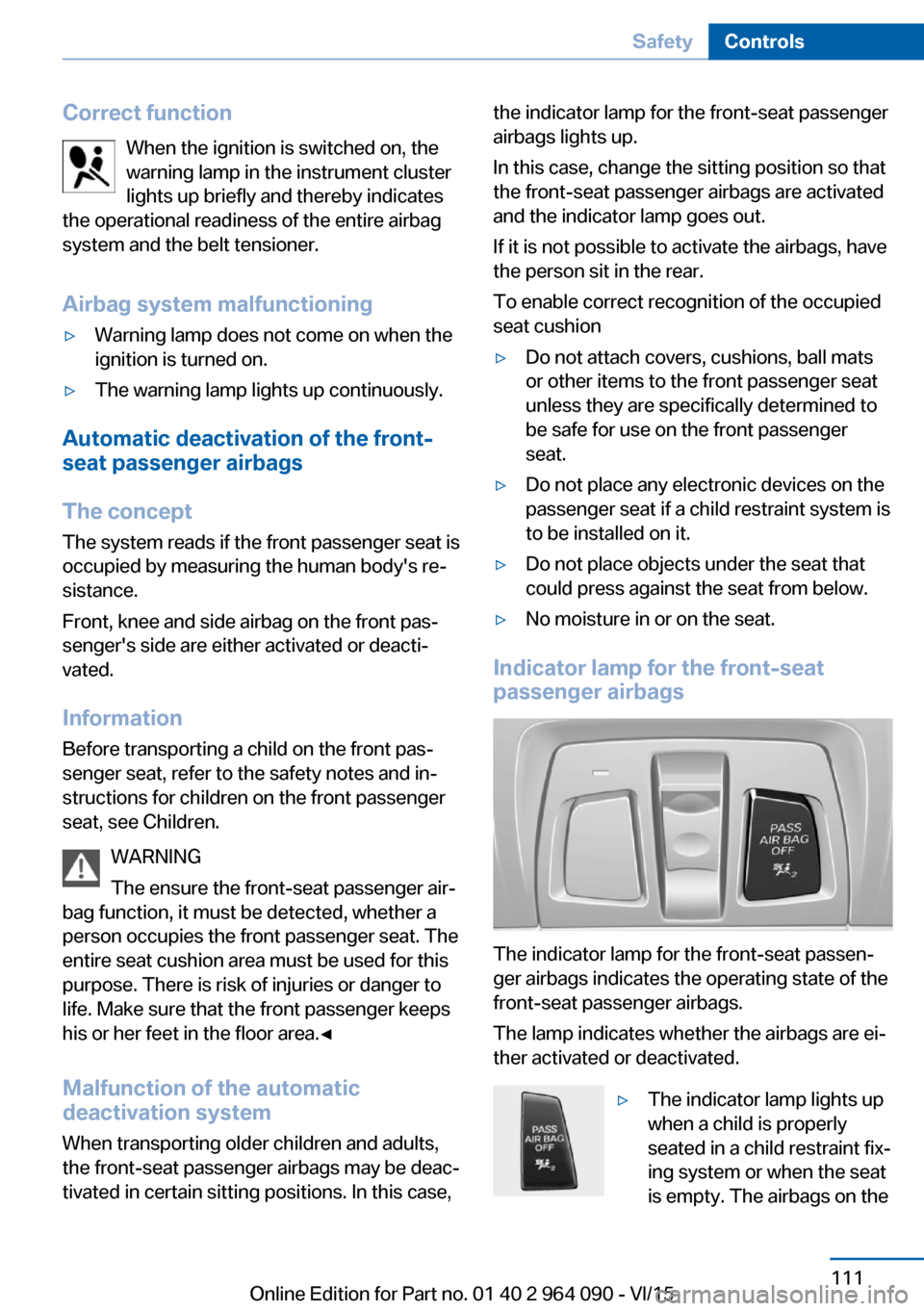
Indicator lamp for the front-seat
passenger airbags
The indicator lamp for the front-seat passen‐
ger airbags indicates the operating state of the
front-seat passenger airbags.
The lamp indicates whether the airbags are ei‐
ther activated or deactivated.
▷The indicator lamp lights up
when a child is properly
seated in a child restraint fix‐
ing system or when the seat
is empty. The airbags on theSeite 111SafetyControls111
Online Edition for Part no. 01 40 2 964 090 - VI/15
Page 112 of 255
front passenger side are not
activated.▷The indicator lamp does not light up when,
e.g., a correctly seated person of sufficient
size is detected on the seat. The airbags
on the front passenger side are activated.
Detected child seats
The system generally detects children seated
in a child seat, particularly in child seats re‐
quired by NHTSA when the vehicle was manu‐ factured. After installing a child seat, make
sure that the indicator lamp for the front-seat
passenger airbags lights up. This indicates
that the child seat has been detected and the
front-seat passenger airbags are not activated.
Strength of the driver's and front-seat
passenger airbag
The explosive power that activates driver's/
front passenger's airbags very much depends
on the positions of the driver's/front passeng‐ er's seat.
With a respective message appearing on Con‐
trol Display calibrate the front seats to keep the accuracy of this function over the long-
term.
Calibrating the front seats WARNING
There is risk of jamming when moving
the seats. There is risk of injuries or risk of
property damage. Make sure that the area of
movement of the seat is clear prior to any ad‐
justment.◀
A corresponding message appears on the
Control Display.
1.Press the switch and move the respective
seat all the way forward.2.Press the switch forward again. The seat
still moves forward slightly.3.Readjust the seat to the desired position.The calibration procedure is completed when
the message on the Control Display disap‐
pears.
If the message continues to be displayed, re‐
peat the calibration.
If the message does not disappear after a re‐
peat calibration, have the system checked as
soon as possible.
Tire Pressure Monitor TPM
The concept The system monitors tire inflation pressure in
the four mounted tires. The system warns you
if there is a significant loss of pressure in one
or more tires. For this purpose, sensors in the
tire valves measure the tire inflation pressure
and tire temperature.
Information With use of the system observe further infor‐
mation found under Tire inflation pressure, re‐
fer to page 200.
Functional requirements
The system must have been reset with the
correct tire inflation pressure; otherwise, relia‐
ble signaling of tire inflation pressure loss is
not assured.
Reset the system after each adjustment of the
tire inflation pressure and after every tire or
wheel change.
Always use wheels with TPM electronics to
ensure that the system will operate properly.
Status display The current status of the Tire Pressure Moni‐
tor TPM can be displayed on the Control Dis‐
play, e.g., whether or not the TPM is active.
On the Control Display:1."Vehicle info"2."Vehicle status"Seite 112ControlsSafety112
Online Edition for Part no. 01 40 2 964 090 - VI/15
Page 113 of 255
3. "Tire Pressure Monitor (TPM)"
The status is displayed.
Status control display Tire and system status are indicated by the
color of the wheels and a text message on the
Control Display.
All wheels green System is active and will issue a warning rela‐
tive to the tire inflation pressures stored during
the last reset.
One wheel is yellow A flat tire or major drop in inflation pressure in
the indicated tire.
All wheels are yellow A flat tire or major drop in inflation pressure in
several tires.
Wheels, gray The system cannot detect a flat tire. Reasons
for this may be:
▷The system is being reset.▷Malfunction.
Status information
The status control display additionally shows
the current tire inflation pressures and, de‐
pending on the model, tire temperatures. It
shows the actual values read; they may vary depending on driving style or weather condi‐
tions.
Carry out reset Reset the system after each adjustment of the
tire inflation pressure and after every tire or
wheel change.
On the Control Display and on the vehicle:
1."Vehicle info"2."Vehicle status"3. "Perform reset"4.Start the engine - do not drive off.5.Reset tire inflation pressure: "Perform
reset".6.Drive away.
The wheels are displayed in gray and the sta‐
tus is displayed.
After driving faster than 19 mph/30 km/h for a
short period, the set tire inflation pressures are
accepted as reference values. The reset is
completed automatically while driving.
After a successfully completed Reset, the
wheels on the Control Display are shown in
green and "Tire Pressure Monitor (TPM)
active" is displayed.
You may interrupt this trip at any time. When
you continue the reset resumes automatically.
Low tire pressure message The yellow warning lamp lights up. A
Check Control message is displayed.
▷There is a flat tire or a major loss in
tire inflation pressure.▷No reset was performed for the system.
The system therefore issues a warning
based on the tire inflation pressures before
the last reset.1.Reduce your speed and stop cautiously.
Avoid sudden braking and steering maneu‐
vers.2.Identify the damaged wheel. Do so by
checking the tire inflation pressure using
the Mobility System. To correct the tire in‐
flation pressure3.Repair flat tire with the Mobility System or
replace the damaged wheel.
A low tire inflation pressure might turn on DSC
Dynamic Stability Control.
Seite 113SafetyControls113
Online Edition for Part no. 01 40 2 964 090 - VI/15
Page 114 of 255
Required tire inflation pressure check
message
A Check Control message is displayed in the
following situations▷The system has detected a wheel change,
but no reset was done.▷Inflation was not carried out according to
specifications.▷The tire inflation pressure has fallen below
the level of the last confirmation.
In this case:
▷Check the tire pressure and correct as
needed.▷Carry out a reset of the system after a tire
change.
System limits
The system does not function properly if a re‐
set has not been carried out, e.g., a flat tire is
reported though tire inflation pressures are
correct.
The tire inflation pressure depends on the
tire's temperature. Driving or exposure to the
sun will increase the tire's temperature, thus
increasing the tire inflation pressure. The tire
inflation pressure is reduced when the tire
temperature falls again. These circumstances
may cause a warning when temperatures fall
very sharply.
The system cannot indicate sudden serious
tire damage caused by external circumstances.
Malfunction The yellow warning lamp flashes and
then lights up continuously. A Check
Control message is displayed. No flat
tire or loss of tire inflation pressure can be de‐
tected.
Examples and recommendations in the follow‐
ing situations:
▷A wheel without TPM electronics is
mounted: Have it checked by a dealer’sservice center or another qualified service
center or repair shop as needed.▷Malfunction: Have system checked by a
dealer’s service center or another qualified
service center or repair shop.▷TPM was unable to complete the reset.
Reset the system again.▷Interference through systems or devices
with the same radio frequency: After leav‐
ing the area of the interference, the system
automatically becomes active again.
Declaration according to NHTSA/
FMVSS 138 Tire Pressure Monitoring
System
Each tire, including the spare (if provided)
should be checked monthly when cold and in‐
flated to the inflation pressure recommended
by the vehicle manufacturer on the vehicle
placard or tire inflation pressure label. (If your
vehicle has tires of a different size than the size
indicated on the vehicle placard or tire inflation
pressure label, you should determine the
proper tire inflation pressure for those tires.)
As an added safety feature, your vehicle has
been equipped with a tire pressure monitoring
system (TPMS) that illuminates a low tire pres‐
sure telltale when one or more of your tires is
significantly under-inflated. Accordingly, when
the low tire pressure telltale illuminates, you
should stop and check your tires as soon as
possible, and inflate them to the proper pres‐
sure. Driving on a significantly under-inflated
tire causes the tire to overheat and can lead to
tire failure. Under-inflation also reduces fuel ef‐
ficiency and tire tread life, and may affect the
vehicle's handling and stopping ability. Please
note that the TPMS is not a substitute for
proper tire maintenance, and it is the driver's
responsibility to maintain correct tire pressure,
even if under-inflation has not reached the
level to trigger illumination of the TPMS low
tire pressure telltale. Your vehicle has also
been equipped with a TPMS malfunction indi‐
cator to indicate when the system is not oper‐
Seite 114ControlsSafety114
Online Edition for Part no. 01 40 2 964 090 - VI/15
Page 115 of 255
ating properly. The TPMS malfunction indica‐
tor is combined with the low tire pressure
telltale. When the system detects a malfunc‐
tion, the telltale will flash for approximately one
minute and then remain continuously illumi‐
nated. This sequence will continue upon sub‐
sequent vehicle start-ups as long as the mal‐
function exists. When the malfunction indicator
is illuminated, the system may not be able to
detect or signal low tire pressure as intended.
TPMS malfunctions may occur for a variety of
reasons, including the installation of replace‐
ment or alternate tires or wheels on the vehicle
that prevent the TPMS from functioning prop‐
erly. Always check the TPMS malfunction tell‐
tale after replacing one or more tires or wheels
on your vehicle to ensure that the replacement
or alternate tires and wheels allow the TPMS
to continue to function properly.
FTM Flat Tire Monitor The conceptThe system detects tire inflation pressure losson the basis of rotation speed differences be‐
tween the individual wheels while driving.
In the event of a tire inflation pressure loss, the
diameter and therefore the rotational speed of
the corresponding wheel changes. This will be
detected and reported as a flat tire.
The system does not measure the actual infla‐
tion pressure in the tires.
Functional requirements
The system must have been initialized when
the tire inflation pressure was correct; other‐
wise, reliable flagging of a flat tire is not as‐
sured. Initialize the system after each correc‐ tion of the tire inflation pressure and after
every tire or wheel change.Status display
The current status of the Flat Tire Monitor can
be displayed on the Control Display, e.g.,
whether or not the FTM is active.
On the Control Display:1."Vehicle info"2."Vehicle status"3. "Flat Tire Monitor (FTM)"
The status is displayed.
Initialization
When initializing the once set inflation tire
pressures serve as reference values in order to
detect a flat tire. Initialization is started by con‐
firming the tire inflation pressures.
Do not initialize the system when driving with
snow chains.
On the Control Display:
1."Vehicle info"2."Vehicle status"3. "Perform reset"4.Start the engine - do not drive off.5.Start the initialization with "Perform reset".6.Drive away.
The initialization is completed while driving,
which can be interrupted at any time.
The initialization automatically continues when
driving resumes.
Indication of a flat tire The yellow warning lamp lights up. A
Check Control message is displayed.
There is a flat tire or a major loss in tire
inflation pressure.
1.Reduce your speed and stop cautiously.
Avoid sudden braking and steering maneu‐
vers.2.Identify the damaged wheel. Do so by
checking the tire inflation pressure usingSeite 115SafetyControls115
Online Edition for Part no. 01 40 2 964 090 - VI/15