fog light BMW X6 2013 E71 Owner's Manual
[x] Cancel search | Manufacturer: BMW, Model Year: 2013, Model line: X6, Model: BMW X6 2013 E71Pages: 327, PDF Size: 7.71 MB
Page 16 of 327
CockpitVehicle equipment
This chapter describes all series equipment as
well as country-specific and special equipment
offered for this model series.Therefore, it alsodescribes equipment that may not be found in
your vehicle, for instance due to the selected
special equipment or the country version. This
also applies to safety-related functions and
systems.
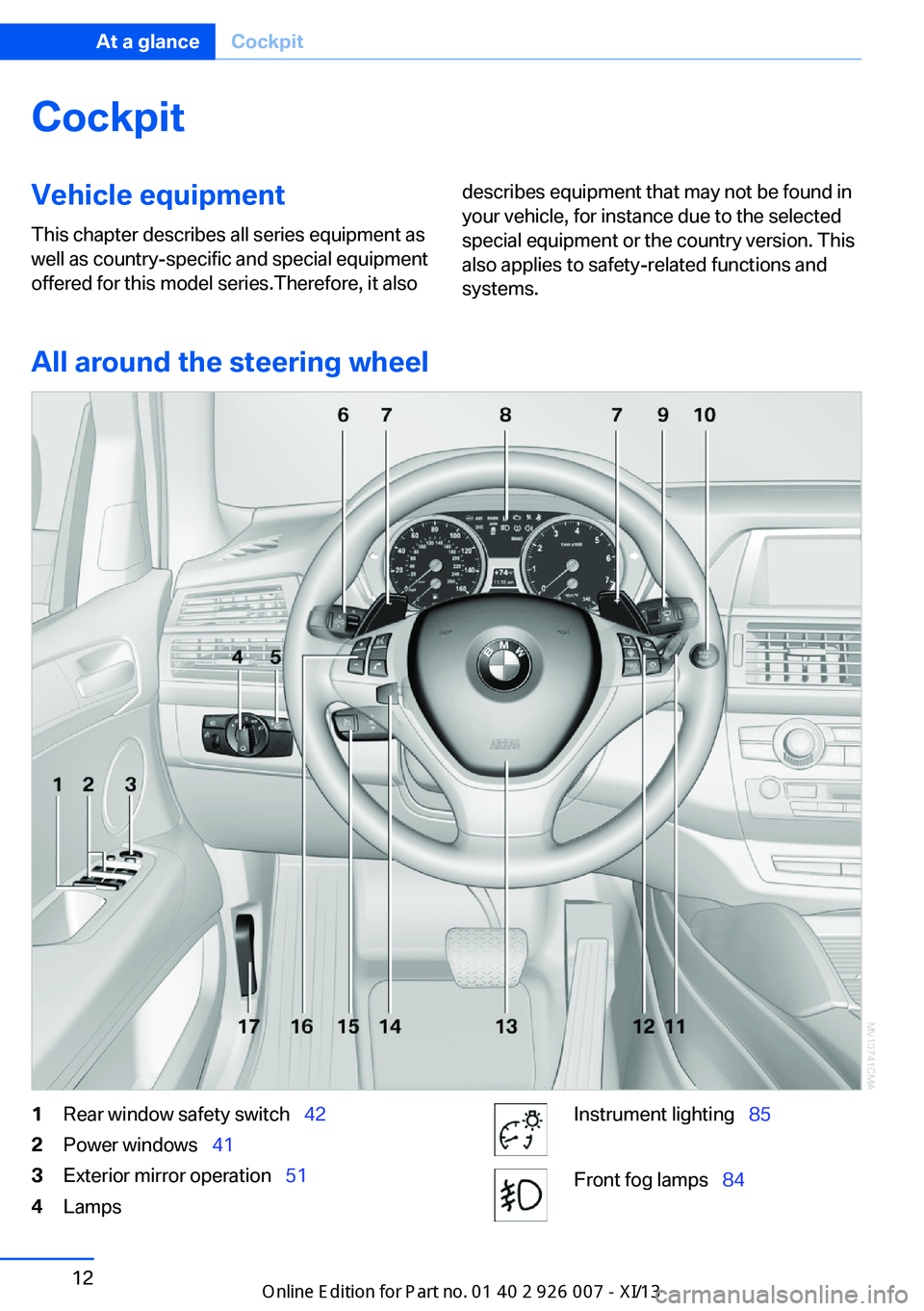
All around the steering wheel
1Rear window safety switch 422Power windows 413Exterior mirror operation 514LampsInstrument lighting 85Front fog lamps 84Seite 12At a glanceCockpit12
Online Edition for Part no. 01 40 2 910 876 - VII/13
Page 19 of 327
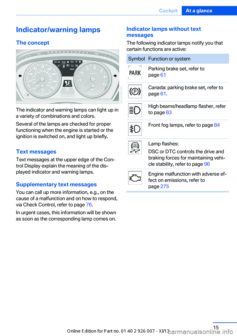
Indicator/warning lampsThe concept
The indicator and warning lamps can light up in
a variety of combinations and colors.
Several of the lamps are checked for proper
functioning when the engine is started or the
ignition is switched on, and light up briefly.
Text messages Text messages at the upper edge of the Con‐
trol Display explain the meaning of the dis‐
played indicator and warning lamps.
Supplementary text messages
You can call up more information, e.g., on the
cause of a malfunction and on how to respond,
via Check Control, refer to page 76.
In urgent cases, this information will be shown
as soon as the corresponding lamp comes on.
Indicator lamps without text
messages
The following indicator lamps notify you that
certain functions are active:SymbolFunction or systemParking brake set, refer to
page 61Canada: parking brake set, refer to
page 61.High beams/headlamp flasher, refer
to page 83Front fog lamps, refer to page 84Lamp flashes:
DSC or DTC controls the drive and
braking forces for maintaining vehi‐
cle stability, refer to page 96Engine malfunction with adverse ef‐
fect on emissions, refer to
page 275Seite 15CockpitAt a glance15
Online Edition for Part no. 01 40 2 910 876 - VII/13
Page 86 of 327
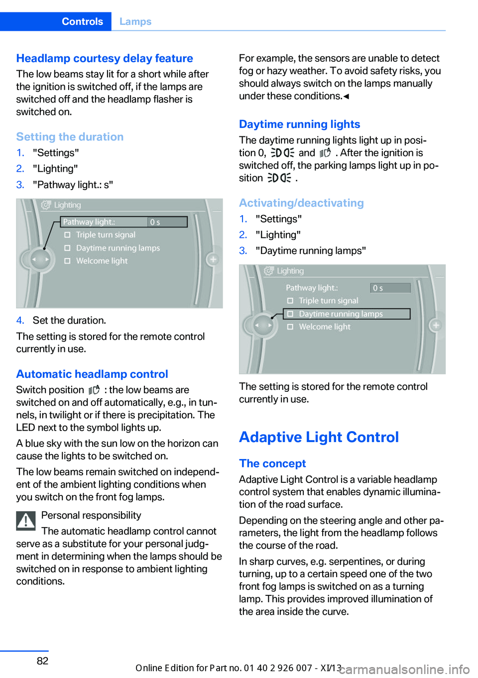
Headlamp courtesy delay feature
The low beams stay lit for a short while after
the ignition is switched off, if the lamps are
switched off and the headlamp flasher is
switched on.
Setting the duration1."Settings"2."Lighting"3."Pathway light.: s"4.Set the duration.
The setting is stored for the remote control
currently in use.
Automatic headlamp control
Switch position
: the low beams are
switched on and off automatically, e.g., in tun‐
nels, in twilight or if there is precipitation. The
LED next to the symbol lights up.
A blue sky with the sun low on the horizon can
cause the lights to be switched on.
The low beams remain switched on independ‐
ent of the ambient lighting conditions when
you switch on the front fog lamps.
Personal responsibility
The automatic headlamp control cannot
serve as a substitute for your personal judg‐
ment in determining when the lamps should be
switched on in response to ambient lighting
conditions.
For example, the sensors are unable to detect
fog or hazy weather. To avoid safety risks, you
should always switch on the lamps manually
under these conditions.◀
Daytime running lights The daytime running lights light up in posi‐
tion 0,
and . After the ignition is
switched off, the parking lamps light up in po‐
sition
.
Activating/deactivating
1."Settings"2."Lighting"3."Daytime running lamps"
The setting is stored for the remote control
currently in use.
Adaptive Light Control
The concept Adaptive Light Control is a variable headlamp
control system that enables dynamic illumina‐
tion of the road surface.
Depending on the steering angle and other pa‐
rameters, the light from the headlamp follows
the course of the road.
In sharp curves, e.g. serpentines, or during
turning, up to a certain speed one of the two
front fog lamps is switched on as a turning
lamp. This provides improved illumination of
the area inside the curve.
Seite 82ControlsLamps82
Online Edition for Part no. 01 40 2 910 876 - VII/13
Page 88 of 327
The system responds to light from oncoming
traffic and traffic driving ahead of you, and to
adequate illumination, e.g., in towns and cities.
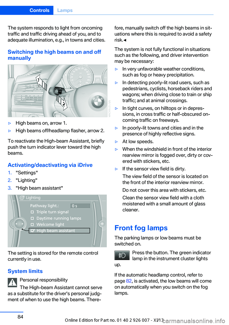
Switching the high beams on and offmanually▷High beams on, arrow 1.▷High beams off/headlamp flasher, arrow 2.
To reactivate the High-beam Assistant, briefly
push the turn indicator lever toward the high
beams.
Activating/deactivating via iDrive
1."Settings"2."Lighting"3."High beam assistant"
The setting is stored for the remote control
currently in use.
System limits Personal responsibility
The High-beam Assistant cannot serve
as a substitute for the driver's personal judg‐
ment of when to use the high beams. There‐
fore, manually switch off the high beams in sit‐
uations where this is required to avoid a safety
risk.◀
The system is not fully functional in situations
such as the following, and driver intervention
may be necessary:▷In very unfavorable weather conditions,
such as fog or heavy precipitation.▷In detecting poorly-lit road users, such as
pedestrians, cyclists, horseback riders and
wagons; when driving close to train or ship
traffic; and at animal crossings.▷In tight curves, on hilltops or in depres‐
sions, in cross traffic or half-obscured on‐
coming traffic on freeways.▷In poorly-lit towns and cities and in the
presence of highly reflective signs.▷At low speeds.▷When the windshield in front of the interior
rearview mirror is fogged over, dirty or cov‐
ered with stickers, etc.▷If the sensor view field is dirty.
The view field of the sensor is located on
the front of the interior rearview mirror.
Do not cover this area with stickers, etc.
Clean the sensor view field with a cloth
moistened with a small amount of glass
cleaner.
Front fog lamps
The parking lamps or low beams must be
switched on.
Press the button. The green indicator
lamp in the instrument cluster lights
up.
If the automatic headlamp control, refer to
page 82, is activated, the low beams will come
on automatically when you switch on the fog
lamps.
Seite 84ControlsLamps84
Online Edition for Part no. 01 40 2 910 876 - VII/13
Page 98 of 327
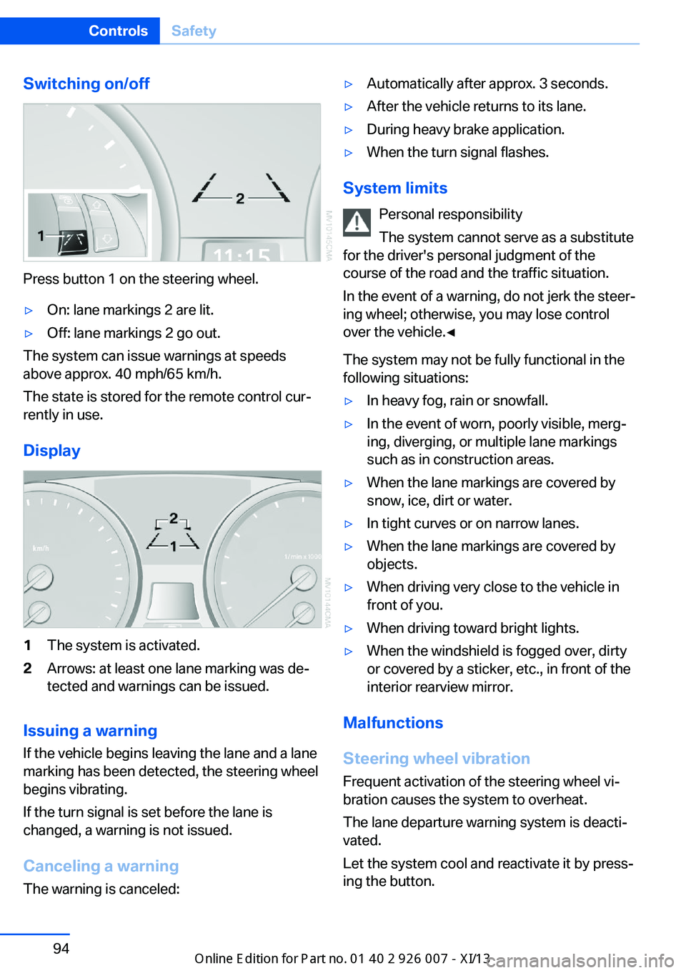
Switching on/off
Press button 1 on the steering wheel.
▷On: lane markings 2 are lit.▷Off: lane markings 2 go out.
The system can issue warnings at speeds
above approx. 40 mph/65 km/h.
The state is stored for the remote control cur‐
rently in use.
Display
1The system is activated.2Arrows: at least one lane marking was de‐
tected and warnings can be issued.
Issuing a warning
If the vehicle begins leaving the lane and a lane
marking has been detected, the steering wheel
begins vibrating.
If the turn signal is set before the lane is
changed, a warning is not issued.
Canceling a warning The warning is canceled:
▷Automatically after approx. 3 seconds.▷After the vehicle returns to its lane.▷During heavy brake application.▷When the turn signal flashes.
System limits
Personal responsibility
The system cannot serve as a substitute
for the driver's personal judgment of the
course of the road and the traffic situation.
In the event of a warning, do not jerk the steer‐
ing wheel; otherwise, you may lose control
over the vehicle.◀
The system may not be fully functional in the
following situations:
▷In heavy fog, rain or snowfall.▷In the event of worn, poorly visible, merg‐
ing, diverging, or multiple lane markings
such as in construction areas.▷When the lane markings are covered by
snow, ice, dirt or water.▷In tight curves or on narrow lanes.▷When the lane markings are covered by
objects.▷When driving very close to the vehicle in
front of you.▷When driving toward bright lights.▷When the windshield is fogged over, dirty
or covered by a sticker, etc., in front of the
interior rearview mirror.
Malfunctions
Steering wheel vibration
Frequent activation of the steering wheel vi‐
bration causes the system to overheat.
The lane departure warning system is deacti‐
vated.
Let the system cool and reactivate it by press‐
ing the button.
Seite 94ControlsSafety94
Online Edition for Part no. 01 40 2 910 876 - VII/13
Page 113 of 327
system activated, resting your foot on the acel‐
erator pedal will cause the system not to brake
even if necessary. Be certain that floormats or
other objects on the vehicle floor do not inter‐
fere with movement of the acccelerator
pedal.◀
Limits of automatic braking
While active cruise control is capable of
braking your vehicle automatically when you
approach a slower vehicle ahead, it is impor‐
tant to be aware that the ability of the system
to apply the brakes is also limited, e.g. when
you reduce your desired speed sharply. lt uses
only a portion of braking system capacity and
does not utilize the full capacity of the vehicle
braking system. Therefore, the system cannot
decrease your speed for large differences in
speed between your vehicle and the vehicle
ahead. Examples: when you approach a vehicle
traveling at a much lower speed than your own
speed such as approaching a toll booth or
when a much slower vehicle cuts in front of
you at close range.◀
Cruise controlThe concept The system is functional at speeds beginning
at approx. 20 mph/30 km/h.
The speed specified using the lever on the
steering column is maintained.
The system brakes on downhill gradients if en‐
gine braking action is insufficient.
Do not use cruise control
Do not use the system if unfavorable
conditions make it impossible to drive at a con‐
stant speed, for instance:▷On curvy roads.▷In heavy traffic.▷On slippery roads, in fog, snow or rain, or
on a loose road surface.Otherwise, you could lose control of the vehi‐
cle and cause an accident.◀
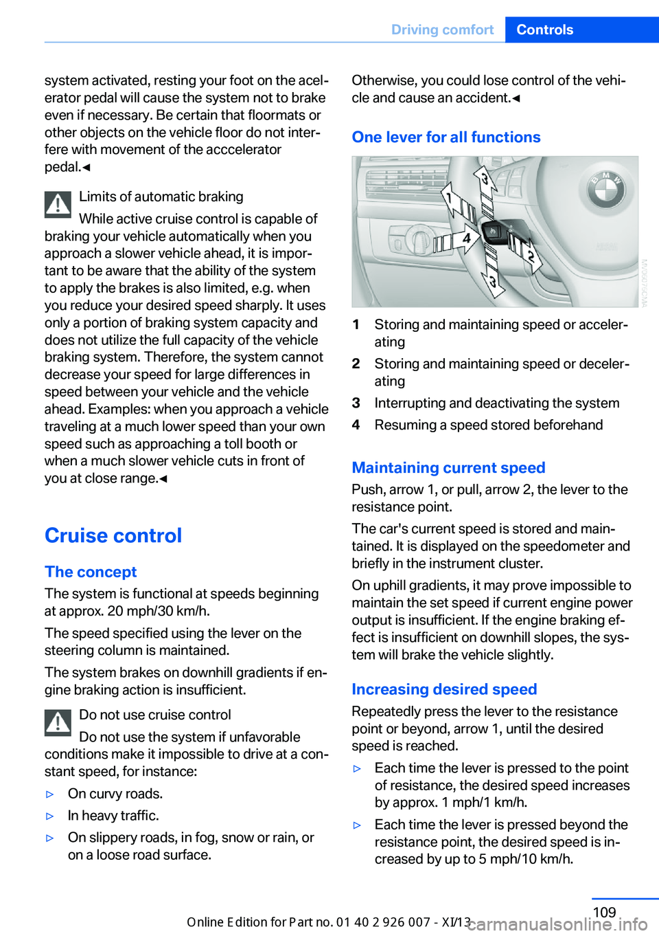
One lever for all functions1Storing and maintaining speed or acceler‐
ating2Storing and maintaining speed or deceler‐
ating3Interrupting and deactivating the system4Resuming a speed stored beforehand
Maintaining current speed
Push, arrow 1, or pull, arrow 2, the lever to the
resistance point.
The car's current speed is stored and main‐ tained. It is displayed on the speedometer and
briefly in the instrument cluster.
On uphill gradients, it may prove impossible to
maintain the set speed if current engine power
output is insufficient. If the engine braking ef‐
fect is insufficient on downhill slopes, the sys‐
tem will brake the vehicle slightly.
Increasing desired speed
Repeatedly press the lever to the resistance
point or beyond, arrow 1, until the desired
speed is reached.
▷Each time the lever is pressed to the point
of resistance, the desired speed increases
by approx. 1 mph/1 km/h.▷Each time the lever is pressed beyond the
resistance point, the desired speed is in‐
creased by up to 5 mph/10 km/h.Seite 109Driving comfortControls109
Online Edition for Part no. 01 40 2 910 876 - VII/13
Page 281 of 327
To avoid possible injury or equipment damage
when replacing bulbs, observe any instructions
provided by the bulb manufacturer.◀
Do not perform work/bulb replacement
on xenon headlamps
Have any work on the xenon lighting system,
including bulb replacement, performed only by
a service center.
Due to the high voltage present in the system,
there is the danger of fatal injuries if work is
carried out improperly.◀
Do not touch the bulbs
Do not touch the glass of new bulbs with
your bare hands, as even minute amounts of
contamination will burn into the bulb's surface
and reduce its service life.
Use a clean tissue, cloth or something similar,
or hold the bulb by its base.◀
Light-emitting diodes LED
Light-emitting diodes installed behind translu‐
cent lenses serve as the light source for many
of the controls, displays and other equipment
in your vehicle.
These light-emitting diodes, which operate us‐
ing a concept similar to that applied in conven‐
tional lasers, are officially designated as
Class 1 light-emitting diodes.
Do not remove the covers
Do not remove the covers, and never
stare into the unfiltered light for several hours; otherwise, irritation of the retina could result.◀
Headlamp glass
Condensation can form on the inside of the
headlamps in cool or humid weather. When
you drive with the lights switched on, the con‐
densation evaporates after a short time. The
headlamps do not need to be changed.
If the condensation in the headlamps does not
evaporate after trips with the lights switchedon, and the amount of moisture in the head‐
lamps increases, for example if water droplets
form, have them checked by your service cen‐
ter.
Changing the lamps
Xenon headlamps
Notes
Because of the long life of these bulbs, the
likelihood of failure is very low. Switching the
lamps on and off frequently shortens their life.
If a xenon bulb fails, switch on the front fog
lamps and continue the trip with great care.
Comply with local regulations.
Do not perform work/bulb replacement
on xenon headlamps
Have any work on the xenon lighting system,
including bulb replacement, performed only by
a service center.
Due to the high voltage present in the system,
there is the danger of fatal injuries if work is
carried out improperly.◀
Follow the general instructions on lamps and
bulbs, refer to page 276.
Parking lamps, roadside parking
lamps, daytime running lights
The illustration shows the left side of the en‐
gine compartment.Seite 277Replacing componentsMobility277
Online Edition for Part no. 01 40 2 910 876 - VII/13
Page 282 of 327
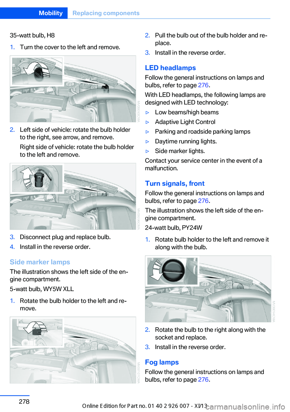
35-watt bulb, H81.Turn the cover to the left and remove.2.Left side of vehicle: rotate the bulb holder
to the right, see arrow, and remove.
Right side of vehicle: rotate the bulb holder
to the left and remove.3.Disconnect plug and replace bulb.4.Install in the reverse order.
Side marker lamps
The illustration shows the left side of the en‐
gine compartment.
5-watt bulb, WY5W XLL
1.Rotate the bulb holder to the left and re‐
move.2.Pull the bulb out of the bulb holder and re‐
place.3.Install in the reverse order.
LED headlamps
Follow the general instructions on lamps and
bulbs, refer to page 276.
With LED headlamps, the following lamps are
designed with LED technology:
▷Low beams/high beams▷Adaptive Light Control▷Parking and roadside parking lamps▷Daytime running lights.▷Side marker lights.
Contact your service center in the event of a
malfunction.
Turn signals, frontFollow the general instructions on lamps and
bulbs, refer to page 276.
The illustration shows the left side of the en‐
gine compartment.
24-watt bulb, PY24W
1.Rotate bulb holder to the left and remove it
along with the bulb.2.Rotate the bulb to the right along with the
socket and replace.3.Install in the reverse order.
Fog lamps
Follow the general instructions on lamps and
bulbs, refer to page 276.
Seite 278MobilityReplacing components278
Online Edition for Part no. 01 40 2 910 876 - VII/13
Page 317 of 327
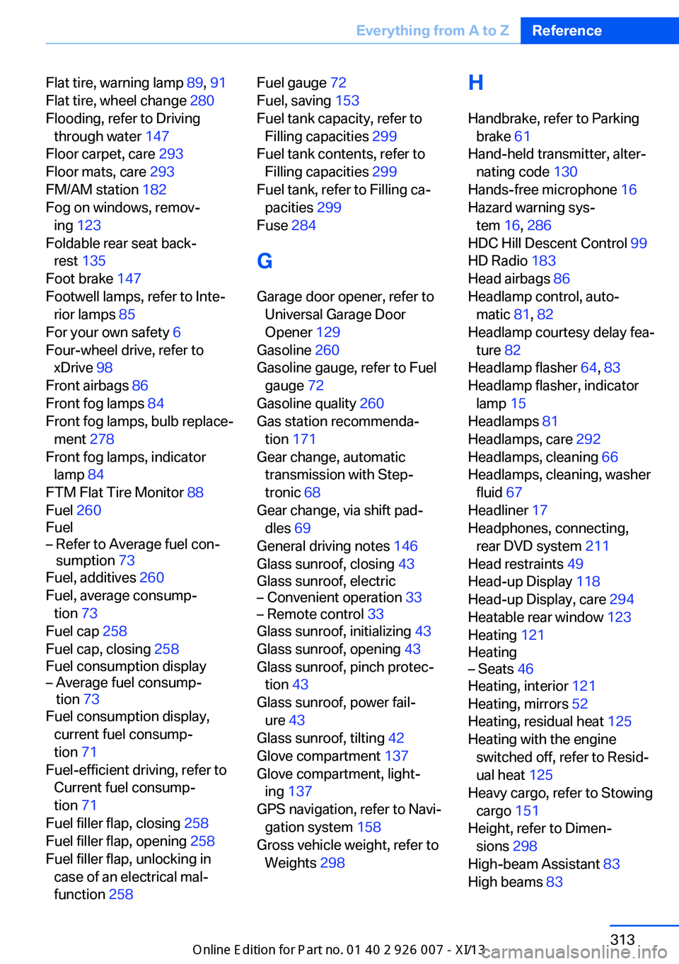
Flat tire, warning lamp 89, 91
Flat tire, wheel change 280
Flooding, refer to Driving through water 147
Floor carpet, care 293
Floor mats, care 293
FM/AM station 182
Fog on windows, remov‐ ing 123
Foldable rear seat back‐ rest 135
Foot brake 147
Footwell lamps, refer to Inte‐ rior lamps 85
For your own safety 6
Four-wheel drive, refer to xDrive 98
Front airbags 86
Front fog lamps 84
Front fog lamps, bulb replace‐ ment 278
Front fog lamps, indicator lamp 84
FTM Flat Tire Monitor 88
Fuel 260
Fuel– Refer to Average fuel con‐
sumption 73
Fuel, additives 260
Fuel, average consump‐ tion 73
Fuel cap 258
Fuel cap, closing 258
Fuel consumption display
– Average fuel consump‐
tion 73
Fuel consumption display,
current fuel consump‐
tion 71
Fuel-efficient driving, refer to Current fuel consump‐
tion 71
Fuel filler flap, closing 258
Fuel filler flap, opening 258
Fuel filler flap, unlocking in case of an electrical mal‐
function 258
Fuel gauge 72
Fuel, saving 153
Fuel tank capacity, refer to Filling capacities 299
Fuel tank contents, refer to Filling capacities 299
Fuel tank, refer to Filling ca‐ pacities 299
Fuse 284
G
Garage door opener, refer to Universal Garage Door
Opener 129
Gasoline 260
Gasoline gauge, refer to Fuel gauge 72
Gasoline quality 260
Gas station recommenda‐ tion 171
Gear change, automatic transmission with Step‐
tronic 68
Gear change, via shift pad‐ dles 69
General driving notes 146
Glass sunroof, closing 43
Glass sunroof, electric– Convenient operation 33– Remote control 33
Glass sunroof, initializing 43
Glass sunroof, opening 43
Glass sunroof, pinch protec‐ tion 43
Glass sunroof, power fail‐ ure 43
Glass sunroof, tilting 42
Glove compartment 137
Glove compartment, light‐ ing 137
GPS navigation, refer to Navi‐ gation system 158
Gross vehicle weight, refer to Weights 298
H
Handbrake, refer to Parking brake 61
Hand-held transmitter, alter‐ nating code 130
Hands-free microphone 16
Hazard warning sys‐ tem 16, 286
HDC Hill Descent Control 99
HD Radio 183
Head airbags 86
Headlamp control, auto‐ matic 81, 82
Headlamp courtesy delay fea‐ ture 82
Headlamp flasher 64, 83
Headlamp flasher, indicator lamp 15
Headlamps 81
Headlamps, care 292
Headlamps, cleaning 66
Headlamps, cleaning, washer fluid 67
Headliner 17
Headphones, connecting, rear DVD system 211
Head restraints 49
Head-up Display 118
Head-up Display, care 294
Heatable rear window 123
Heating 121
Heating– Seats 46
Heating, interior 121
Heating, mirrors 52
Heating, residual heat 125
Heating with the engine switched off, refer to Resid‐
ual heat 125
Heavy cargo, refer to Stowing cargo 151
Height, refer to Dimen‐ sions 298
High-beam Assistant 83
High beams 83
Seite 313Everything from A to ZReference313
Online Edition for Part no. 01 40 2 910 876 - VII/13
Page 324 of 327
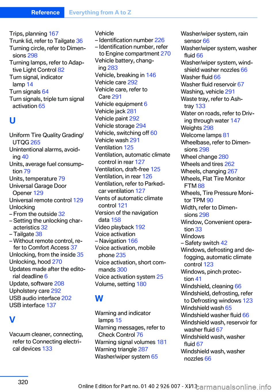
Trips, planning 167
Trunk lid, refer to Tailgate 36
Turning circle, refer to Dimen‐ sions 298
Turning lamps, refer to Adap‐ tive Light Control 82
Turn signal, indicator lamp 14
Turn signals 64
Turn signals, triple turn signal activation 65
U Uniform Tire Quality Grading/ UTQG 265
Unintentional alarms, avoid‐ ing 40
Units, average fuel consump‐ tion 79
Units, temperature 79
Universal Garage Door Opener 129
Universal remote control 129
Unlocking– From the outside 32– Setting the unlocking char‐
acteristics 32– Tailgate 38– Without remote control, re‐
fer to Comfort Access 37
Unlocking, from the inside 35
Unlocking, hood 270
Updates made after the edito‐ rial deadline 6
Update, software 208
Upholstery care 292
USB audio interface 202
USB interface 137
V
Vacuum cleaner, connecting, refer to Connecting electri‐
cal devices 133
Vehicle– Identification number 226– Identification number, refer
to Engine compartment 270
Vehicle battery, chang‐
ing 283
Vehicle, breaking in 146
Vehicle care 292
Vehicle care, refer to Care 291
Vehicle equipment 6
Vehicle jack 281
Vehicle paint 292
Vehicle storage 294
Vehicle, switching off 60
Vehicle wash 291
Ventilation 125
Ventilation, automatic climate control in rear 127
Ventilation, draft-free 125
Ventilation, in rear 126
Ventilation, refer to Parked- car ventilation 127
Vents of automatic climate
control 121
Version of the navigation data 158
Video playback 192
Voice activation
– Navigation 166
Voice activation, mobile
phone 235
Voice activation, short com‐ mands 300
Voice activation system 25
Volume, setting 180
W Warning and indicator lamps 15
Warning messages, refer to Check Control 76
Warning signal volumes 181
Warning triangle 287
Washer/wiper system 65
Washer/wiper system, rain
sensor 66
Washer/wiper system, washer fluid 66
Washer/wiper system, wind‐ shield washer nozzles 66
Washer fluid 66
Washer fluid reservoir 67
Washing, vehicle 291
Waste tray, refer to Ash‐ tray 133
Water on roads, refer to Driv‐ ing through water 147
Weights 298
Welcome lamps 81
Wheelbase, refer to Dimen‐ sions 298
Wheel change 280
Wheels and tires 262
Wheels, changing 267
Wheels, Flat Tire Monitor FTM 88
Wheels, Tire Pressure Moni‐ tor TPM 90
Width, refer to Dimen‐ sions 298
Window, Convenient opera‐ tion 33
Windows– Safety switch 42
Windows, defrosting and de‐
fogging, automatic climate
control 123
Windows, pinch protec‐ tion 41
Windshield, cleaning 66
Windshield, defrosting, refer to Defrosting windows 123
Windshield wash 65
Windshield washer fluid 66
Windshield wash, reservoir for washer fluid 67
Windshield wash, washer fluid 67
Windshield wash, washer nozzles 66
Seite 320ReferenceEverything from A to Z320
Online Edition for Part no. 01 40 2 910 876 - VII/13