tow BMW X6 2014 F16 Owner's Guide
[x] Cancel search | Manufacturer: BMW, Model Year: 2014, Model line: X6, Model: BMW X6 2014 F16Pages: 259, PDF Size: 5.92 MB
Page 180 of 259
Cargo area
Cargo cover
Note Do not deposit heavy objects
Do not deposit heavy or hard objects on
the cargo cover. Otherwise, they may pose a
risk to occupants, such as during braking and
evasive maneuvers.◀
General information
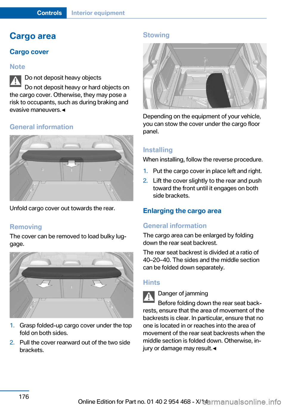
Unfold cargo cover out towards the rear.
RemovingThe cover can be removed to load bulky lug‐
gage.
1.Grasp folded-up cargo cover under the top
fold on both sides.2.Pull the cover rearward out of the two side
brackets.Stowing
Depending on the equipment of your vehicle,
you can stow the cover under the cargo floor
panel.
Installing When installing, follow the reverse procedure.
1.Put the cargo cover in place left and right.2.Lift the cover slightly to the rear and push
toward the front until it engages on both
side brackets.
Enlarging the cargo area
General information
The cargo area can be enlarged by folding
down the rear seat backrest.
The rear seat backrest is divided at a ratio of
40–20–40. The sides and the middle section
can be folded down separately.
Hints Danger of jamming
Before folding down the rear seat back‐
rests, ensure that the area of movement of the
backrests is clear. In particular, ensure that no
one is located in or reaches into the area of
movement of the rear seat backrests when the
middle section is folded down. Otherwise, in‐
jury or damage may result.◀
Seite 176ControlsInterior equipment176
Online Edition for Part no. 01 40 2 954 468 - X/14
Page 182 of 259
Storage compartmentsVehicle features and optionsThis chapter describes all standard, country-
specific and optional features offered with the
series. It also describes features that are not
necessarily available in your car, e. g., due to
the selected options or country versions. This
also applies to safety-related functions and
systems.
Hints No loose objects in the car's interior
Do not stow any objects in the car's inte‐
rior without securing them; otherwise, they
may present a danger to occupants e.g., during
braking and evasive maneuvers.◀
Do not place anti-slip mats on the dash‐
board
Do not place anti-slip mats on the dashboard.
The mat materials could damage the dash‐
board.◀
Storage compartments The following storage compartments are avail‐
able in the vehicle interior:▷Glove compartment on the front passenger
side, refer to page 178.▷Glove compartment on the driver's side,
refer to page 179.▷Compartments in the doors, refer to
page 179.▷Storage compartment on the center arm‐
rest, refer to page 179.▷Center armrest, refer to page 179.▷Glasses compartment, refer to page 180.Glove compartment
Front passenger side
Note Close the glove compartment again im‐
mediately
Close the glove compartment immediately af‐
ter use while driving; otherwise, injury may oc‐
cur during accidents.◀
Opening
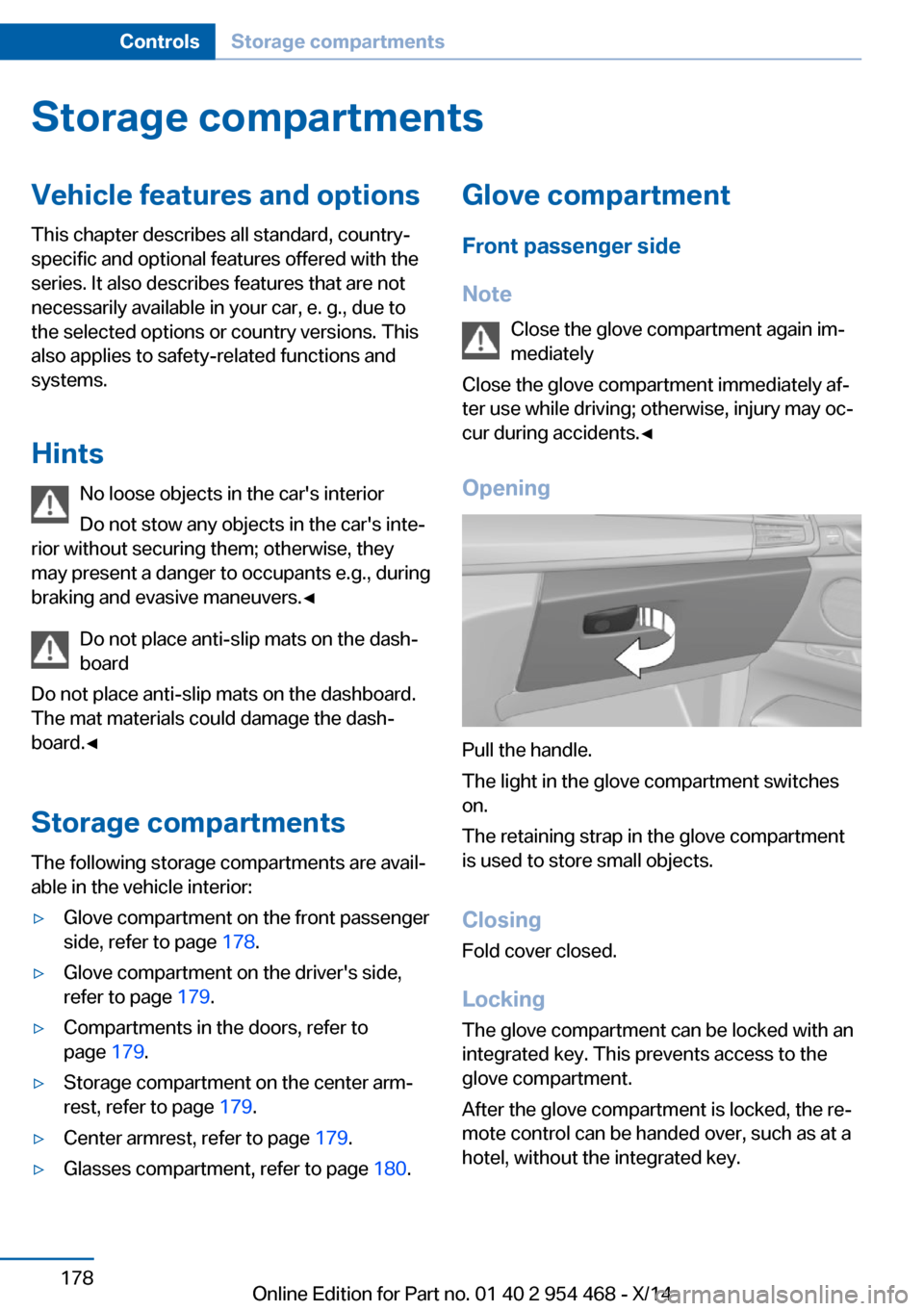
Pull the handle.
The light in the glove compartment switches
on.
The retaining strap in the glove compartment
is used to store small objects.
ClosingFold cover closed.
Locking
The glove compartment can be locked with an
integrated key. This prevents access to the
glove compartment.
After the glove compartment is locked, the re‐
mote control can be handed over, such as at a
hotel, without the integrated key.
Seite 178ControlsStorage compartments178
Online Edition for Part no. 01 40 2 954 468 - X/14
Page 183 of 259
Driver's side
Note Close the glove compartment again im‐
mediately
Close the glove compartment immediately af‐
ter use while driving; otherwise, injury may oc‐
cur during accidents.◀
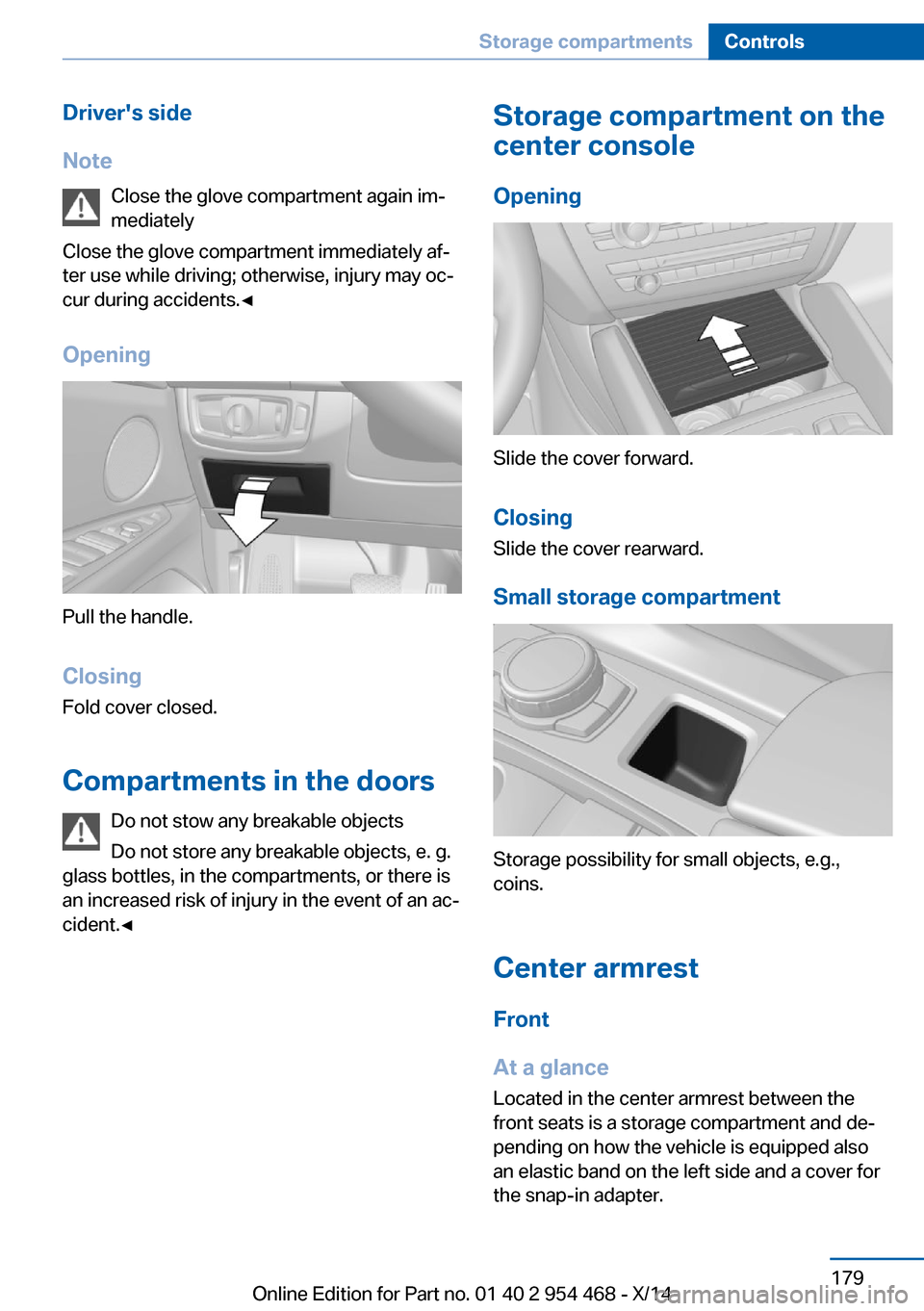
Opening
Pull the handle.
ClosingFold cover closed.
Compartments in the doors Do not stow any breakable objects
Do not store any breakable objects, e. g.
glass bottles, in the compartments, or there is
an increased risk of injury in the event of an ac‐
cident.◀
Storage compartment on the
center console
Opening
Slide the cover forward.
Closing Slide the cover rearward.
Small storage compartment
Storage possibility for small objects, e.g.,
coins.
Center armrest Front
At a glance
Located in the center armrest between the
front seats is a storage compartment and de‐ pending on how the vehicle is equipped also
an elastic band on the left side and a cover for
the snap-in adapter.
Seite 179Storage compartmentsControls179
Online Edition for Part no. 01 40 2 954 468 - X/14
Page 194 of 259
LoadingVehicle features and options
This chapter describes all standard, country-
specific and optional features offered with the
series. It also describes features that are not
necessarily available in your car, e. g., due to
the selected options or country versions. This
also applies to safety-related functions and
systems.
Hints Overloading the vehicle
To avoid exceeding the approved ca‐
pacity of the tires, never overload the vehicle.
Overloading can lead to overheating and in‐
creases the rate at which damage develops in‐
side the tires. This could result in a sudden
loss of tire inflation pressure.◀
No fluids in the cargo area
Make sure that fluids do not leak into the
cargo area; otherwise, the vehicle may be dam‐
aged.◀
Heavy and hard objects
Do not stow any heavy and hard objects
in the car's interior without securing them; oth‐
erwise, they may present a danger to occu‐
pants, e.g., during braking and evasive maneu‐
vers.◀
Determining the load limit1.Locate the following statement on your ve‐
hicle’s placard:▷The combined weight of occupants
and cargo should never exceed XXX kg
or YYY lbs. Otherwise, damage to thevehicle and unstable driving situations
may result.2.Determine the combined weight of the
driver and passengers that will be riding in
your vehicle.3.Subtract the combined weight of the driver
and passengers from XXX kilograms or
YYY pounds.4.The resulting figure equals the available
amount of cargo and luggage load ca‐
pacity.
For example, if the YYY amount equals
1,000 lbs and there will be four 150 lbs
passengers in your vehicle, the amount of
available cargo and luggage load capacity
is 400 lbs: 1,000 lbs minus 600 lbs =
400 lbs.5.Determine the combined weight of lug‐
gage and cargo being loaded on the vehi‐
cle. That weight may not safely exceed the
available cargo and luggage load capacity
calculated in Step 4.Seite 190Driving tipsLoading190
Online Edition for Part no. 01 40 2 954 468 - X/14
Page 195 of 259
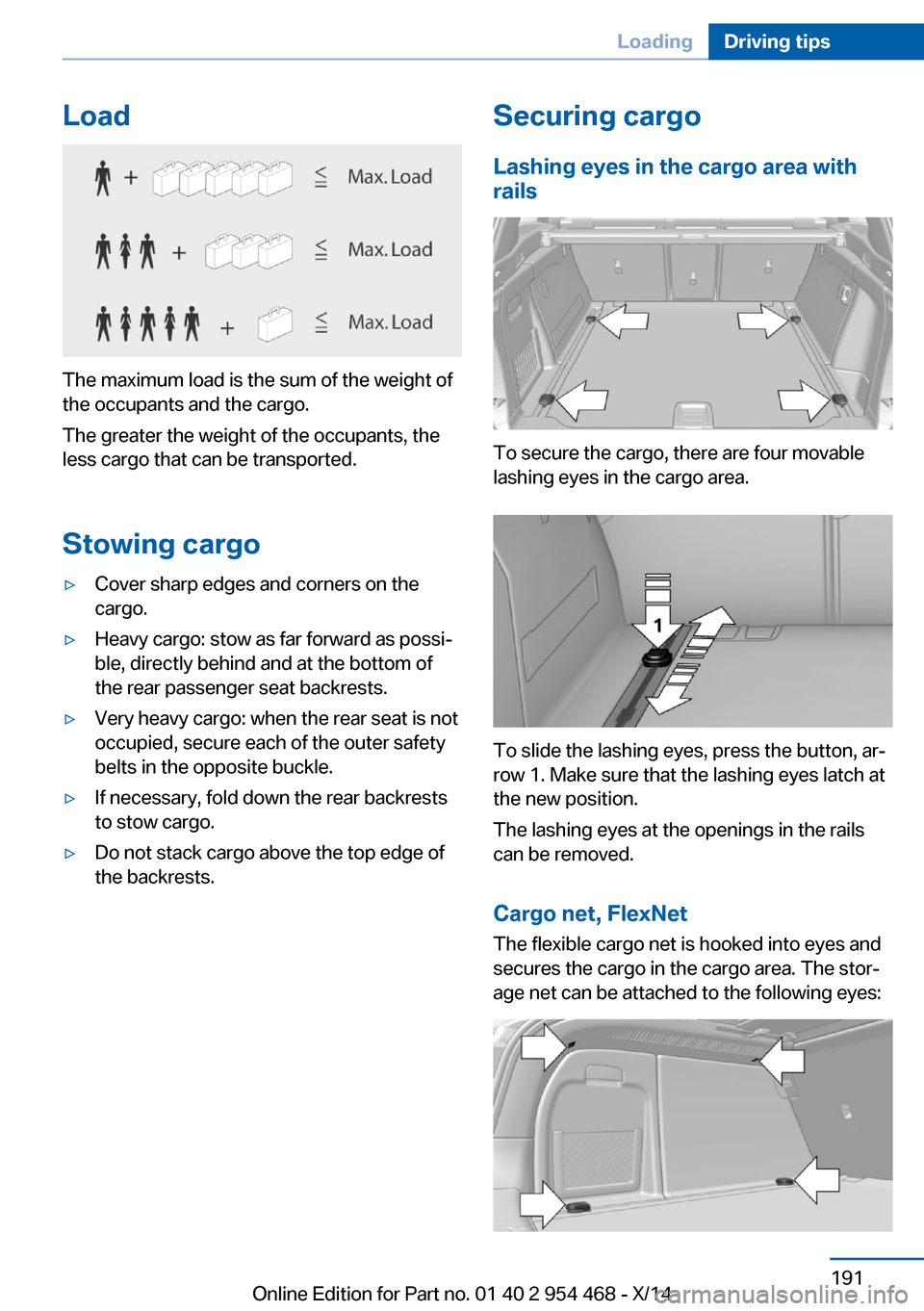
Load
The maximum load is the sum of the weight of
the occupants and the cargo.
The greater the weight of the occupants, the
less cargo that can be transported.
Stowing cargo
▷Cover sharp edges and corners on the
cargo.▷Heavy cargo: stow as far forward as possi‐
ble, directly behind and at the bottom of
the rear passenger seat backrests.▷Very heavy cargo: when the rear seat is not
occupied, secure each of the outer safety
belts in the opposite buckle.▷If necessary, fold down the rear backrests
to stow cargo.▷Do not stack cargo above the top edge of
the backrests.Securing cargo
Lashing eyes in the cargo area with
rails
To secure the cargo, there are four movable
lashing eyes in the cargo area.
To slide the lashing eyes, press the button, ar‐
row 1. Make sure that the lashing eyes latch at
the new position.
The lashing eyes at the openings in the rails
can be removed.
Cargo net, FlexNet The flexible cargo net is hooked into eyes and
secures the cargo in the cargo area. The stor‐
age net can be attached to the following eyes:
Seite 191LoadingDriving tips191
Online Edition for Part no. 01 40 2 954 468 - X/14
Page 196 of 259

▷Lashing eyes in the rails.▷Eyes on the cargo area wall.
The eyes are located on both sides of the
cargo area.
Securing cargo
▷Smaller and lighter items: secure with re‐
taining straps or with a cargo net or draw
straps.▷Larger and heavy objects: secure with
cargo straps.
Cargo straps, cargo netting, retaining
straps or draw straps on the lashing eyes in
the cargo area.
Securing cargo
Stow and secure the cargo as described
above; otherwise it may present a danger to
the occupants, e.g., during braking and evasive
maneuvers.◀
Roof-mounted luggage rack Note
Installation only possible with roof rack.
Roof racks are available as special accessories.
Securing
Follow the installation instructions of the roof
rack.
Loading Be sure that adequate clearance is maintained
for tilting and opening the glass sunroof.
Because roof racks raise the vehicle's center
of gravity when loaded, they have a major ef‐
fect on vehicle handling and steering re‐
sponse.
Therefore, note the following when loading
and driving:
▷Do not exceed the approved roof/axle
loads and the approved gross vehicle
weight.▷Distribute the roof load uniformly.▷The roof load should not extend past the
loading area.▷Always place the heaviest pieces on the
bottom.▷Secure the roof luggage firmly, e.g., tie
with ratchet straps.▷Do not let objects project into the opening
path of the tailgate.▷Drive cautiously and avoid sudden acceler‐
ation and braking maneuvers. Take corners
gently.Seite 192Driving tipsLoading192
Online Edition for Part no. 01 40 2 954 468 - X/14
Page 212 of 259
DOT Quality GradesTreadwear
Traction AA A B C
Temperature A B C
All passenger car tires must conform to Fed‐
eral Safety Requirements in addition to these
grades.
Treadwear The treadwear grade is a comparative rating
based on the wear rate of the tire when tested
under controlled conditions on a specified gov‐
ernment test course. For example, a tire
graded 150 would wear one and one-half, 1 g,
times as well on the government course as a
tire graded 100. The relative performance of
tires depends upon the actual conditions of
their use, however, and may depart signifi‐
cantly from the norm due to variations in driv‐
ing habits, service practices and differences in
road characteristics and climate.
Traction
The traction grades, from highest to lowest,
are AA, A, B, and C.
Those grades represent the tire's ability to
stop on wet pavement as measured under
controlled conditions on specified government
test surfaces of asphalt and concrete. A tire
marked C may have poor traction performance.
The traction grade assigned to this tire is
based on straight-ahead braking traction tests,
and does not include acceleration, cornering,
hydroplaning, or peak traction characteristics.
Temperature The temperature grades are A, the highest, B,
and C, representing the tire's resistance to the
generation of heat and its ability to dissipate
heat when tested under controlled conditions
on a specified indoor laboratory test wheel.
Sustained high temperature can cause the ma‐
terial of the tire to degenerate and reduce tire
life, and excessive temperature can lead tosudden tire failure. The grade C corresponds
to a level of performance which all passenger
car tires must meet under the Federal Motor
Vehicle Safety Standard No. 109. Grades Band
A represent higher levels of performance on
the laboratory test wheel than the minimum re‐
quired by law.
Temperature grade for this tire
The temperature grade for this tire is es‐
tablished for a tire that is properly inflated and
not overloaded. Excessive speed, underinfla‐
tion, or excessive loading, either separately or
in combination, can cause heat buildup and
possible tire failure.
If necessary, have the vehicle towed.◀
RSC – Run-flat tires Run-flat tires, refer to page 211, are labeled
with a circular symbol containing the letters
RSC marked on the sidewall.
M+S
Winter and all-season tires with better cold
weather performance than summer tires.
Tire tread
Summer tires
Do not drive with a tire tread depth of less than
0.12 in/3 mm.
There is an increased danger of hydroplaning if
the tire tread depth is less than 0.12 in/3 mm.
Winter tires
Do not drive with a tire tread depth of less than
0.16 in/4 mm.
Below a tread depth of 0.16 in/4 mm, tires are
less suitable for winter operation.Seite 208MobilityWheels and tires208
Online Edition for Part no. 01 40 2 954 468 - X/14
Page 213 of 259
Minimum tread depth
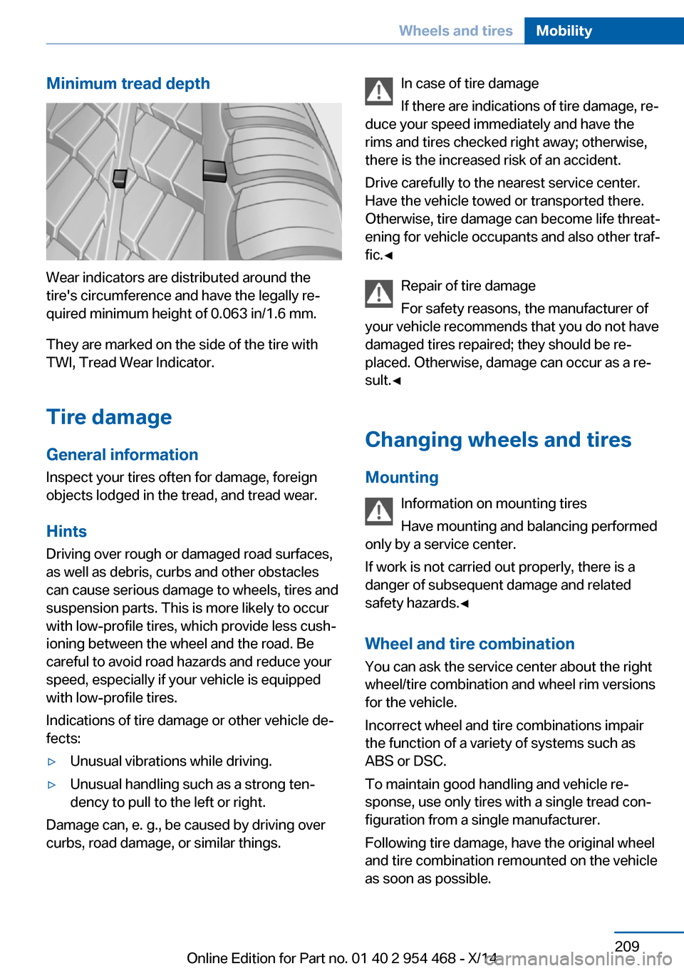
Wear indicators are distributed around the
tire's circumference and have the legally re‐
quired minimum height of 0.063 in/1.6 mm.
They are marked on the side of the tire with
TWI, Tread Wear Indicator.
Tire damage
General information
Inspect your tires often for damage, foreign
objects lodged in the tread, and tread wear.
Hints
Driving over rough or damaged road surfaces,
as well as debris, curbs and other obstacles
can cause serious damage to wheels, tires and
suspension parts. This is more likely to occur
with low-profile tires, which provide less cush‐
ioning between the wheel and the road. Be
careful to avoid road hazards and reduce your
speed, especially if your vehicle is equipped
with low-profile tires.
Indications of tire damage or other vehicle de‐
fects:
▷Unusual vibrations while driving.▷Unusual handling such as a strong ten‐
dency to pull to the left or right.
Damage can, e. g., be caused by driving over
curbs, road damage, or similar things.
In case of tire damage
If there are indications of tire damage, re‐
duce your speed immediately and have the
rims and tires checked right away; otherwise,
there is the increased risk of an accident.
Drive carefully to the nearest service center.
Have the vehicle towed or transported there.
Otherwise, tire damage can become life threat‐
ening for vehicle occupants and also other traf‐
fic.◀
Repair of tire damage
For safety reasons, the manufacturer of
your vehicle recommends that you do not have
damaged tires repaired; they should be re‐
placed. Otherwise, damage can occur as a re‐
sult.◀
Changing wheels and tires
Mounting Information on mounting tires
Have mounting and balancing performed
only by a service center.
If work is not carried out properly, there is a
danger of subsequent damage and related
safety hazards.◀
Wheel and tire combination
You can ask the service center about the right
wheel/tire combination and wheel rim versions
for the vehicle.
Incorrect wheel and tire combinations impair
the function of a variety of systems such as
ABS or DSC.
To maintain good handling and vehicle re‐
sponse, use only tires with a single tread con‐
figuration from a single manufacturer.
Following tire damage, have the original wheel
and tire combination remounted on the vehicle
as soon as possible.Seite 209Wheels and tiresMobility209
Online Edition for Part no. 01 40 2 954 468 - X/14
Page 222 of 259
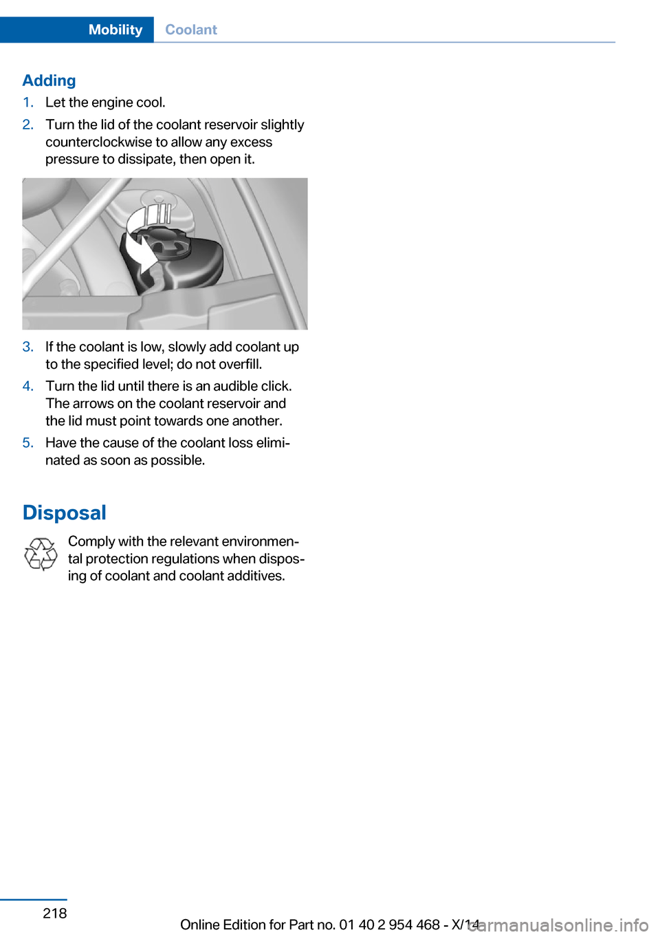
Adding1.Let the engine cool.2.Turn the lid of the coolant reservoir slightly
counterclockwise to allow any excess
pressure to dissipate, then open it.3.If the coolant is low, slowly add coolant up
to the specified level; do not overfill.4.Turn the lid until there is an audible click.
The arrows on the coolant reservoir and
the lid must point towards one another.5.Have the cause of the coolant loss elimi‐
nated as soon as possible.
Disposal
Comply with the relevant environmen‐
tal protection regulations when dispos‐
ing of coolant and coolant additives.
Seite 218MobilityCoolant218
Online Edition for Part no. 01 40 2 954 468 - X/14
Page 228 of 259
Turn signal in exterior mirrorThe turn signals in the exterior mirrors feature
LED technology. Contact your service center
in the event of a malfunction.
Front fog lights/cornering lights
Note
Follow general instructions, refer to page 222.
Replacement
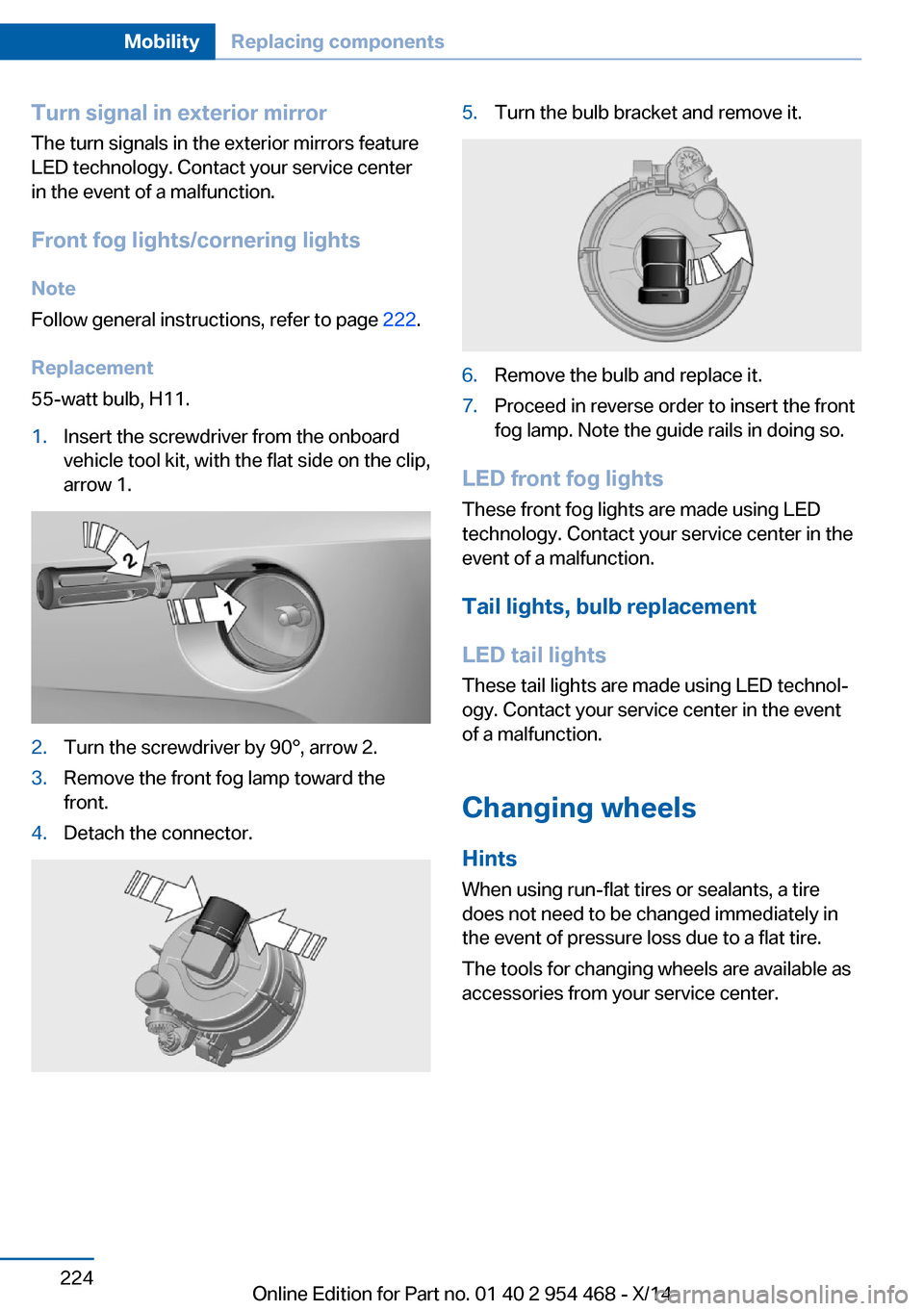
55-watt bulb, H11.1.Insert the screwdriver from the onboard
vehicle tool kit, with the flat side on the clip,
arrow 1.2.Turn the screwdriver by 90°, arrow 2.3.Remove the front fog lamp toward the
front.4.Detach the connector.5.Turn the bulb bracket and remove it.6.Remove the bulb and replace it.7.Proceed in reverse order to insert the front
fog lamp. Note the guide rails in doing so.
LED front fog lights
These front fog lights are made using LED
technology. Contact your service center in the
event of a malfunction.
Tail lights, bulb replacement
LED tail lights
These tail lights are made using LED technol‐
ogy. Contact your service center in the event
of a malfunction.
Changing wheels
Hints When using run-flat tires or sealants, a tire
does not need to be changed immediately in
the event of pressure loss due to a flat tire.
The tools for changing wheels are available as
accessories from your service center.
Seite 224MobilityReplacing components224
Online Edition for Part no. 01 40 2 954 468 - X/14