turn signal BMW Z4 SDRIVE35I 2012 Owners Manual
[x] Cancel search | Manufacturer: BMW, Model Year: 2012, Model line: Z4 SDRIVE35I, Model: BMW Z4 SDRIVE35I 2012Pages: 220, PDF Size: 9.9 MB
Page 13 of 220
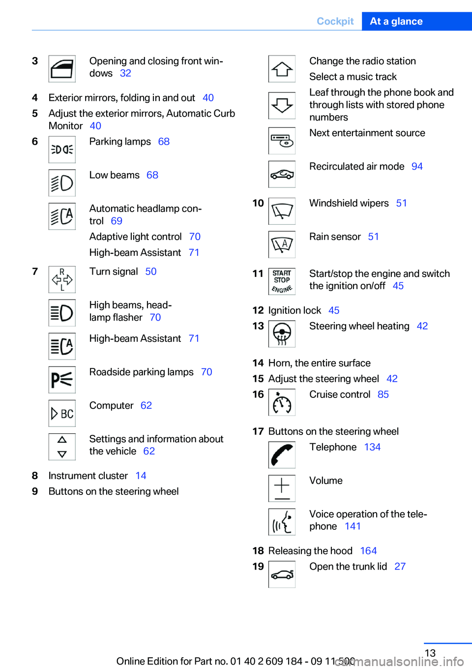
3Opening and closing front win‐
dows 324Exterior mirrors, folding in and out 405Adjust the exterior mirrors, Automatic Curb
Monitor 406Parking lamps 68Low beams 68Automatic headlamp con‐
trol 69
Adaptive light control 70
High-beam Assistant 717Turn signal 50High beams, head‐
lamp flasher 70High-beam Assistant 71Roadside parking lamps 70Computer 62Settings and information about
the vehicle 628Instrument cluster 149Buttons on the steering wheelChange the radio station
Select a music track
Leaf through the phone book and
through lists with stored phone
numbersNext entertainment sourceRecirculated air mode 9410Windshield wipers 51Rain sensor 5111Start/stop the engine and switch
the ignition on/off 4512Ignition lock 4513Steering wheel heating 4214Horn, the entire surface15Adjust the steering wheel 4216Cruise control 8517Buttons on the steering wheelTelephone 134VolumeVoice operation of the tele‐
phone 14118Releasing the hood 16419Open the trunk lid 27Seite 13CockpitAt a glance13
Online Edition for Part no. 01 40 2 609 184 - 09 11 500
Page 14 of 220
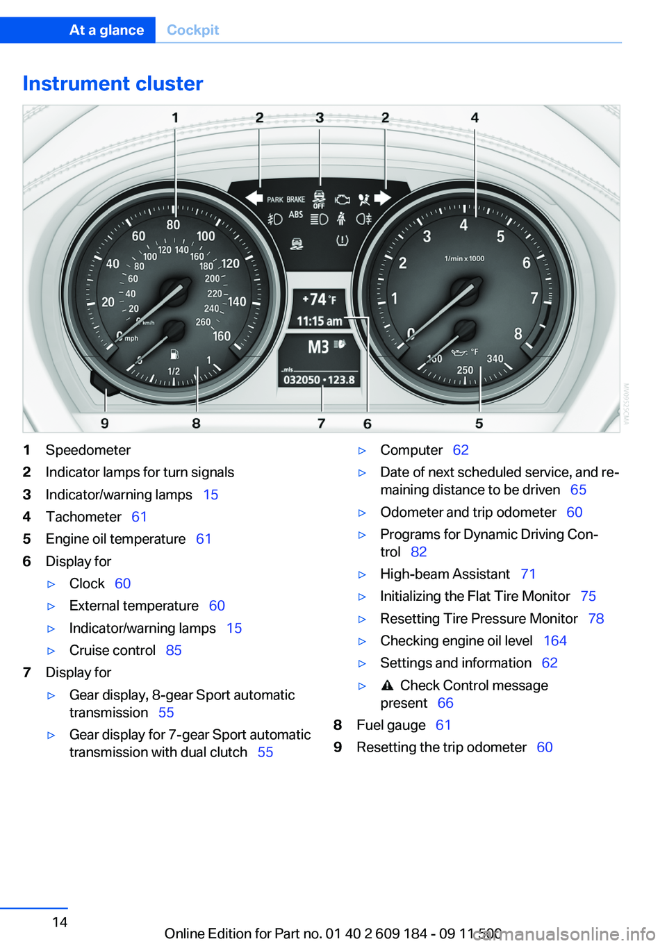
Instrument cluster1Speedometer2Indicator lamps for turn signals3Indicator/warning lamps 154Tachometer 615Engine oil temperature 616Display for▷Clock 60▷External temperature 60▷Indicator/warning lamps 15▷Cruise control 857Display for▷Gear display, 8-gear Sport automatic
transmission 55▷Gear display for 7-gear Sport automatic
transmission with dual clutch 55▷Computer 62▷Date of next scheduled service, and re‐
maining distance to be driven 65▷Odometer and trip odometer 60▷Programs for Dynamic Driving Con‐
trol 82▷High-beam Assistant 71▷Initializing the Flat Tire Monitor 75▷Resetting Tire Pressure Monitor 78▷Checking engine oil level 164▷Settings and information 62▷ Check Control message
present 668Fuel gauge 619Resetting the trip odometer 60Seite 14At a glanceCockpit14
Online Edition for Part no. 01 40 2 609 184 - 09 11 500
Page 21 of 220
▷The remote control used is detected when
the vehicle is unlocked and the stored profile
is called up.▷Your personal settings will be recognized
and called up again even if the vehicle has
been used in the meantime by someone else
with another remote control.
The individual settings are stored for a maximum
of four remote controls. They are stored for two
remote controls if Comfort Access is in use.
Personal Profile settings
The following functions and settings can be
stored in a profile.
More information on the settings can be found
under:
▷Response of the central locking system
when the car is being unlocked, refer to
page 22.▷Automatic locking of the vehicle, refer to
page 26.▷Automatic retrieval of the driver's seat and
exterior mirror positions after unlocking, re‐
fer to page 24.▷Triple turn signal activation, refer to
page 50.▷Settings for the display in the instrument
cluster:▷12h/24h clock format, refer to
page 63.▷Date format, refer to page 63.▷Units of measure for fuel consumption,
distance covered/remaining distances,
and temperature, refer to page 63.▷Light settings:▷Headlamp courtesy delay feature, refer
to page 68.▷Daytime running lights, refer to
page 69.▷High-beam Assistant, refer to
page 71.▷Automatic climate control: AUTO program,
cooling function, and automatic recirculated
air control activated/deactivated, tempera‐
ture, air flow rate, and air distribution, refer
to page 92.▷Entertainment:▷Audio volume, Professional Radio, refer
to page 118.
Central locking system
The concept
The central locking system becomes active
when the driver's door is closed.
The system simultaneously engages and re‐
leases the locks on the following:
▷Doors.▷Trunk lid.▷Fuel filler flap.▷Center armrest.
Operating from the outside
▷Via the remote control.▷Via the driver's door lock.▷In cars with Comfort Access, via the door
handles on the driver's and front passenger
sides.
The following takes place simultaneously when
locking/unlocking the vehicle via the remote
control:
▷The welcome lamps, interior lamps and
courtesy lamps are switched on and off.▷The alarm system is armed or disarmed, re‐
fer to page 30.Seite 21Opening and closingControls21
Online Edition for Part no. 01 40 2 609 184 - 09 11 500
Page 24 of 220
Confirmation signals from the vehicle
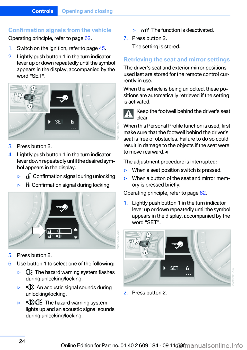
Operating principle, refer to page 62.1.Switch on the ignition, refer to page 45.2.Lightly push button 1 in the turn indicator
lever up or down repeatedly until the symbol
appears in the display, accompanied by the
word "SET".3.Press button 2.4.Lightly push button 1 in the turn indicator
lever down repeatedly until the desired sym‐
bol appears in the display.▷ Confirmation signal during unlocking▷ Confirmation signal during locking5.Press button 2.6.Use button 1 to select one of the following:▷ The hazard warning system flashes
during unlocking/locking.▷ An acoustic signal sounds during
unlocking/locking.▷ The hazard warning system
lights up and an acoustic signal sounds
during unlocking/locking.▷ The function is deactivated.7.Press button 2.
The setting is stored.
Retrieving the seat and mirror settings
The driver's seat and exterior mirror positions
used last are stored for the remote control cur‐
rently in use.
When the vehicle is being unlocked, these po‐
sitions are automatically retrieved if the setting
is activated.
Keep the footwell behind the driver's seat
clear
When this Personal Profile function is used, first
make sure that the footwell behind the driver's
seat is free of obstacles. Failure to do so could
result in damage to the objects if the seat were
to move rearward.◀
The adjustment procedure is interrupted:
▷When a seat position switch is pressed.▷When a button of the seat and mirror mem‐
ory is pressed briefly.
Operating principle, refer to page 62.
1.Lightly push button 1 in the turn indicator
lever up or down repeatedly until the symbol
appears in the display, accompanied by the
word "SET".2.Press button 2.Seite 24ControlsOpening and closing24
Online Edition for Part no. 01 40 2 609 184 - 09 11 500
Page 30 of 220
Replacing the battery
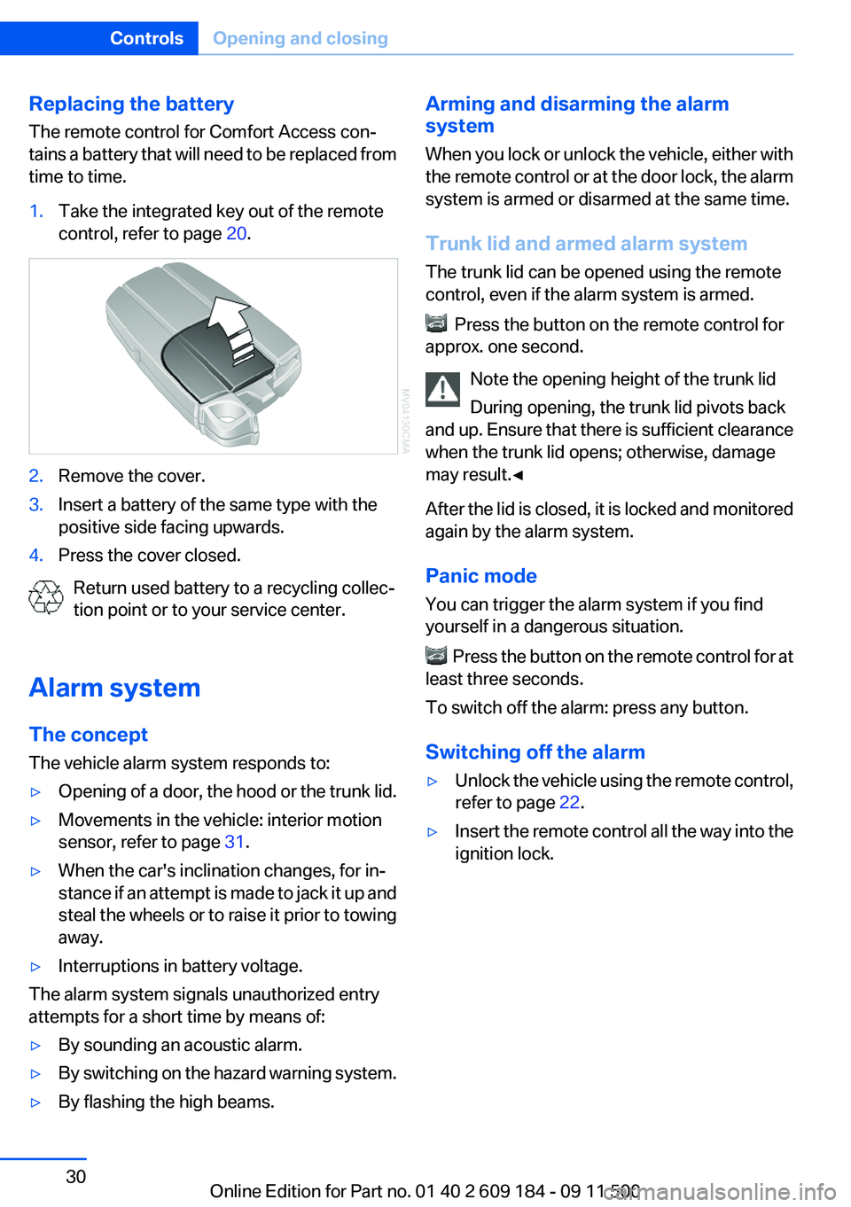
The remote control for Comfort Access con‐
tains a battery that will need to be replaced from
time to time.1.Take the integrated key out of the remote
control, refer to page 20.2.Remove the cover.3.Insert a battery of the same type with the
positive side facing upwards.4.Press the cover closed.
Return used battery to a recycling collec‐
tion point or to your service center.
Alarm system
The concept
The vehicle alarm system responds to:
▷Opening of a door, the hood or the trunk lid.▷Movements in the vehicle: interior motion
sensor, refer to page 31.▷When the car's inclination changes, for in‐
stance if an attempt is made to jack it up and
steal the wheels or to raise it prior to towing
away.▷Interruptions in battery voltage.
The alarm system signals unauthorized entry
attempts for a short time by means of:
▷By sounding an acoustic alarm.▷By switching on the hazard warning system.▷By flashing the high beams.Arming and disarming the alarm
system
When you lock or unlock the vehicle, either with
the remote control or at the door lock, the alarm
system is armed or disarmed at the same time.
Trunk lid and armed alarm system
The trunk lid can be opened using the remote
control, even if the alarm system is armed.
Press the button on the remote control for
approx. one second.
Note the opening height of the trunk lid
During opening, the trunk lid pivots back
and up. Ensure that there is sufficient clearance
when the trunk lid opens; otherwise, damage
may result.◀
After the lid is closed, it is locked and monitored
again by the alarm system.
Panic mode
You can trigger the alarm system if you find
yourself in a dangerous situation.
Press the button on the remote control for at
least three seconds.
To switch off the alarm: press any button.
Switching off the alarm
▷Unlock the vehicle using the remote control,
refer to page 22.▷Insert the remote control all the way into the
ignition lock.Seite 30ControlsOpening and closing30
Online Edition for Part no. 01 40 2 609 184 - 09 11 500
Page 50 of 220
Indicator lamp in Canadian models.
Malfunction
In the event of a failure or malfunction of the
parking brake, secure the vehicle against rolling
using a wheel chock, for example, if you leave
the vehicle.
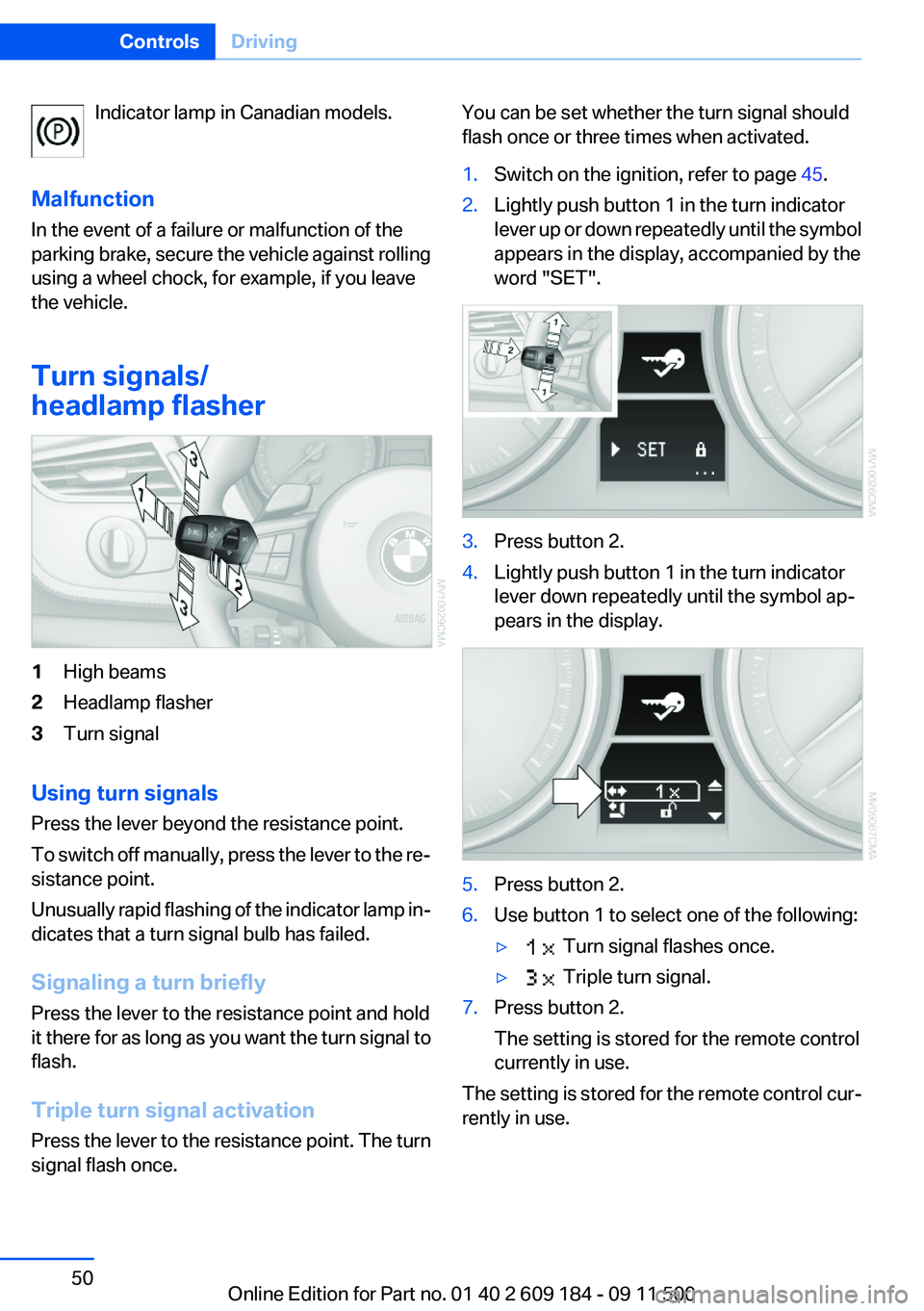
Turn signals/
headlamp flasher1High beams2Headlamp flasher3Turn signal
Using turn signals
Press the lever beyond the resistance point.
To switch off manually, press the lever to the re‐
sistance point.
Unusually rapid flashing of the indicator lamp in‐
dicates that a turn signal bulb has failed.
Signaling a turn briefly
Press the lever to the resistance point and hold
it there for as long as you want the turn signal to
flash.
Triple turn signal activation
Press the lever to the resistance point. The turn
signal flash once.
You can be set whether the turn signal should
flash once or three times when activated.1.Switch on the ignition, refer to page 45.2.Lightly push button 1 in the turn indicator
lever up or down repeatedly until the symbol
appears in the display, accompanied by the
word "SET".3.Press button 2.4.Lightly push button 1 in the turn indicator
lever down repeatedly until the symbol ap‐
pears in the display.5.Press button 2.6.Use button 1 to select one of the following:▷ Turn signal flashes once.▷ Triple turn signal.7.Press button 2.
The setting is stored for the remote control
currently in use.
The setting is stored for the remote control cur‐
rently in use.
Seite 50ControlsDriving50
Online Edition for Part no. 01 40 2 609 184 - 09 11 500
Page 63 of 220
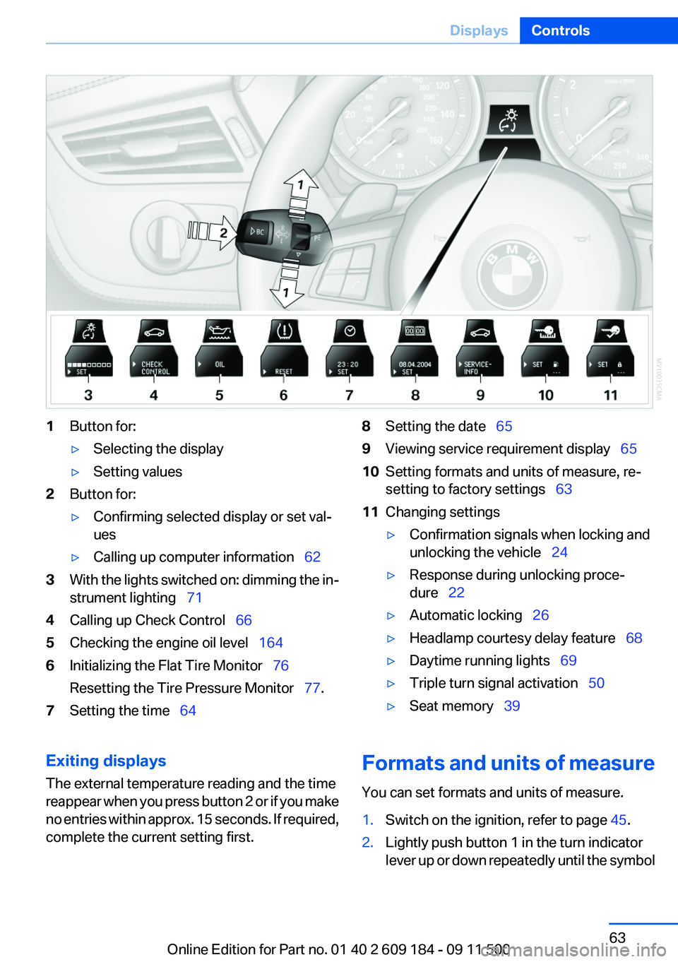
1Button for:▷Selecting the display▷Setting values2Button for:▷Confirming selected display or set val‐
ues▷Calling up computer information 623With the lights switched on: dimming the in‐
strument lighting 714Calling up Check Control 665Checking the engine oil level 1646Initializing the Flat Tire Monitor 76
Resetting the Tire Pressure Monitor 77.7Setting the time 648Setting the date 659Viewing service requirement display 6510Setting formats and units of measure, re‐
setting to factory settings 6311Changing settings▷Confirmation signals when locking and
unlocking the vehicle 24▷Response during unlocking proce‐
dure 22▷Automatic locking 26▷Headlamp courtesy delay feature 68▷Daytime running lights 69▷Triple turn signal activation 50▷Seat memory 39Exiting displays
The external temperature reading and the time
reappear when you press button 2 or if you make
no entries within approx. 15 seconds. If required,
complete the current setting first.Formats and units of measure
You can set formats and units of measure.1.Switch on the ignition, refer to page 45.2.Lightly push button 1 in the turn indicator
lever up or down repeatedly until the symbolSeite 63DisplaysControls63
Online Edition for Part no. 01 40 2 609 184 - 09 11 500
Page 76 of 220
▷When driving on a snowy or slippery road
surface.▷Sporty driving style: slip in the drive wheels,
high lateral acceleration.▷When driving with snow chains.
Initialization
The initialization process adopts the set inflation
tire pressures as reference values for the detec‐
tion of a flat tire. Initialization is started by con‐
firming the inflation pressures.
Do not initialize the system when driving with
snow chains.
Operating principle, refer to page 62.
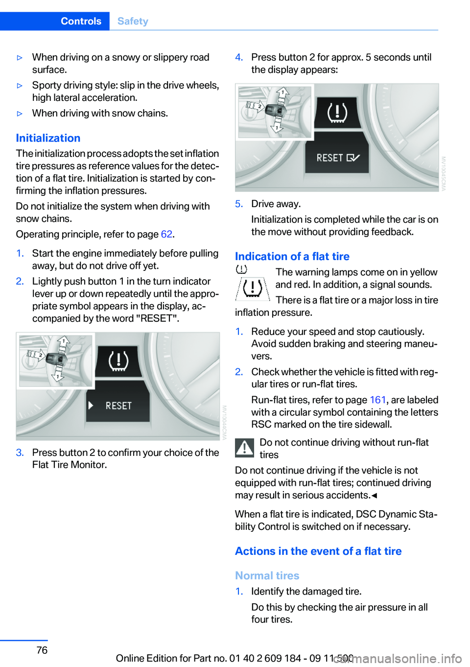
1.Start the engine immediately before pulling
away, but do not drive off yet.2.Lightly push button 1 in the turn indicator
lever up or down repeatedly until the appro‐
priate symbol appears in the display, ac‐
companied by the word "RESET".3.Press button 2 to confirm your choice of the
Flat Tire Monitor.4.Press button 2 for approx. 5 seconds until
the display appears:5.Drive away.
Initialization is completed while the car is on
the move without providing feedback.
Indication of a flat tire
The warning lamps come on in yellow
and red. In addition, a signal sounds.
There is a flat tire or a major loss in tire
inflation pressure.
1.Reduce your speed and stop cautiously.
Avoid sudden braking and steering maneu‐
vers.2.Check whether the vehicle is fitted with reg‐
ular tires or run-flat tires.
Run-flat tires, refer to page 161, are labeled
with a circular symbol containing the letters
RSC marked on the tire sidewall.
Do not continue driving without run-flat
tires
Do not continue driving if the vehicle is not
equipped with run-flat tires; continued driving
may result in serious accidents.◀
When a flat tire is indicated, DSC Dynamic Sta‐
bility Control is switched on if necessary.
Actions in the event of a flat tire
Normal tires
1.Identify the damaged tire.
Do this by checking the air pressure in all
four tires.Seite 76ControlsSafety76
Online Edition for Part no. 01 40 2 609 184 - 09 11 500
Page 78 of 220
in spite of the fact that the tire is filled to the cor‐
rect inflation pressure.
The system is deactivated and is unable to de‐
tect flat tires if a wheel not equipped with TPM
electronics has been mounted, e.g., a compact
wheel, or if TPM is experiencing temporary in‐
terference from other systems or devices that
use the same frequency.
Resetting the system
Reset the system after each correction of the
tire inflation pressure and after every tire or
wheel change.
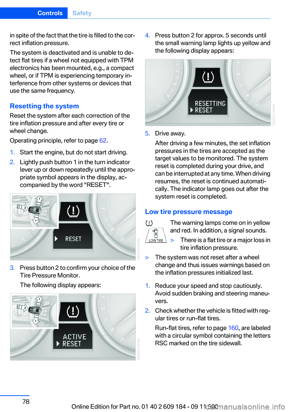
Operating principle, refer to page 62.1.Start the engine, but do not start driving.2.Lightly push button 1 in the turn indicator
lever up or down repeatedly until the appro‐
priate symbol appears in the display, ac‐
companied by the word "RESET".3.Press button 2 to confirm your choice of the
Tire Pressure Monitor.
The following display appears:4.Press button 2 for approx. 5 seconds until
the small warning lamp lights up yellow and
the following display appears:5.Drive away.
After driving a few minutes, the set inflation
pressures in the tires are accepted as the
target values to be monitored. The system
reset is completed during your drive, and
can be interrupted at any time. When driving
resumes, the reset is continued automati‐
cally. The indicator lamp goes out after the
system reset is completed.
Low tire pressure message
The warning lamps come on in yellow
and red. In addition, a signal sounds.
▷There is a flat tire or a major loss in
tire inflation pressure.▷The system was not reset after a wheel
change and thus issues warnings based on
the inflation pressures initialized last.1.Reduce your speed and stop cautiously.
Avoid sudden braking and steering maneu‐
vers.2.Check whether the vehicle is fitted with reg‐
ular tires or run-flat tires.
Run-flat tires , refer to page 160, are labeled
with a circular symbol containing the letters
RSC marked on the tire sidewall.Seite 78ControlsSafety78
Online Edition for Part no. 01 40 2 609 184 - 09 11 500
Page 80 of 220
▷A wheel without TPM electronics is fitted:
have the service center check it if necessary.▷Malfunction: have the system checked by
your service center.▷TPM could not be fully reset. Reset the sys‐
tem again.
The small warning lamp flashes in yel‐
low and then lights up continuously;
the larger warning lamp comes on in
yellow. No flat tire can be detected.
Display in the following situations:
▷Disturbance by systems or devices with the
same radio frequency. After leaving the area
of the disturbance, the system automatically
becomes active again.
Declaration according to NHTSA/
FMVSS 138 Tire Pressure Monitoring
Systems
Each tire, including the spare (if provided)
should be checked monthly when cold and in‐
flated to the inflation pressure recommended by
the vehicle manufacturer on the vehicle placard
or tire inflation pressure label (If your vehicle has
tires of a different size than the size indicated on
the vehicle placard or tire inflation pressure la‐
bel, you should determine the proper tire infla‐
tion pressure for those tires.).
As an added safety feature, your vehicle has
been equipped with a tire pressure monitoring
system (TPMS) that illuminates a low tire pres‐
sure telltale when one or more of your tires is
significantly under-inflated. Accordingly, when
the low tire pressure telltale illuminates, you
should stop and check your tires as soon as
possible, and inflate them to the proper pres‐
sure. Driving on a significantly under-inflated tire
causes the tire to overheat and can lead to tire
failure. Under-inflation also reduces fuel effi‐
ciency and tire tread life, and may affect the ve‐
hicle's handling and stopping ability.
Please note that the TPMS is not a substitute for
proper tire maintenance, and it is the driver's re‐
sponsibility to maintain correct tire pressure,
even if under-inflation has not reached the level
to trigger illumination of the TPMS low tire pres‐
sure telltale.
Your vehicle has also been equipped with a
TPMS malfunction indicator to indicate when
the system is not operating properly. The TPMS
malfunction indicator is combined with the low
tire pressure telltale. When the system detects
a malfunction, the telltale will flash for approxi‐
mately one minute and then remain continu‐
ously illuminated. This sequence will continue
upon subsequent vehicle start-ups as long as
the malfunction exists. When the malfunction
indicator is illuminated, the system may not be
able to detect or signal low tire pressure as in‐
tended. TPMS malfunctions may occur for a va‐
riety of reasons, including the installation of re‐
placement or alternate tires or wheels on the
vehicle that prevent the TPMS from functioning
properly. Always check the TPMS malfunction
telltale after replacing one or more tires or
wheels on your vehicle to ensure that the re‐
placement or alternate tires and wheels allow
the TPMS to continue to function properly.
Brake force display
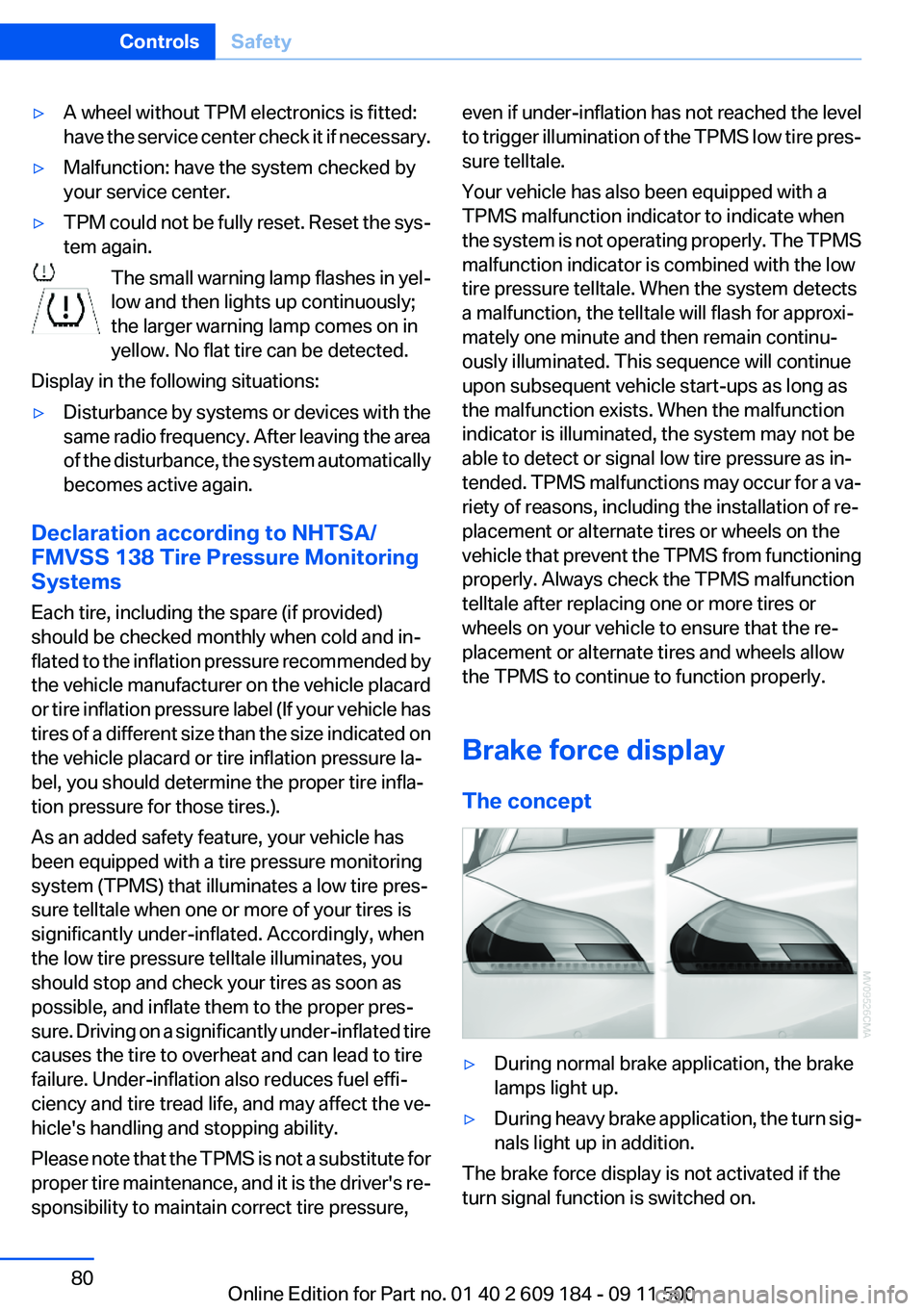
The concept▷During normal brake application, the brake
lamps light up.▷During heavy brake application, the turn sig‐
nals light up in addition.
The brake force display is not activated if the
turn signal function is switched on.
Seite 80ControlsSafety80
Online Edition for Part no. 01 40 2 609 184 - 09 11 500