BMW Z8 2001 Owners Manual
Manufacturer: BMW, Model Year: 2001, Model line: Z8, Model: BMW Z8 2001Pages: 170, PDF Size: 1.64 MB
Page 141 of 170
141n
IndexDataTechnologyRepairsCar careControlsOverview
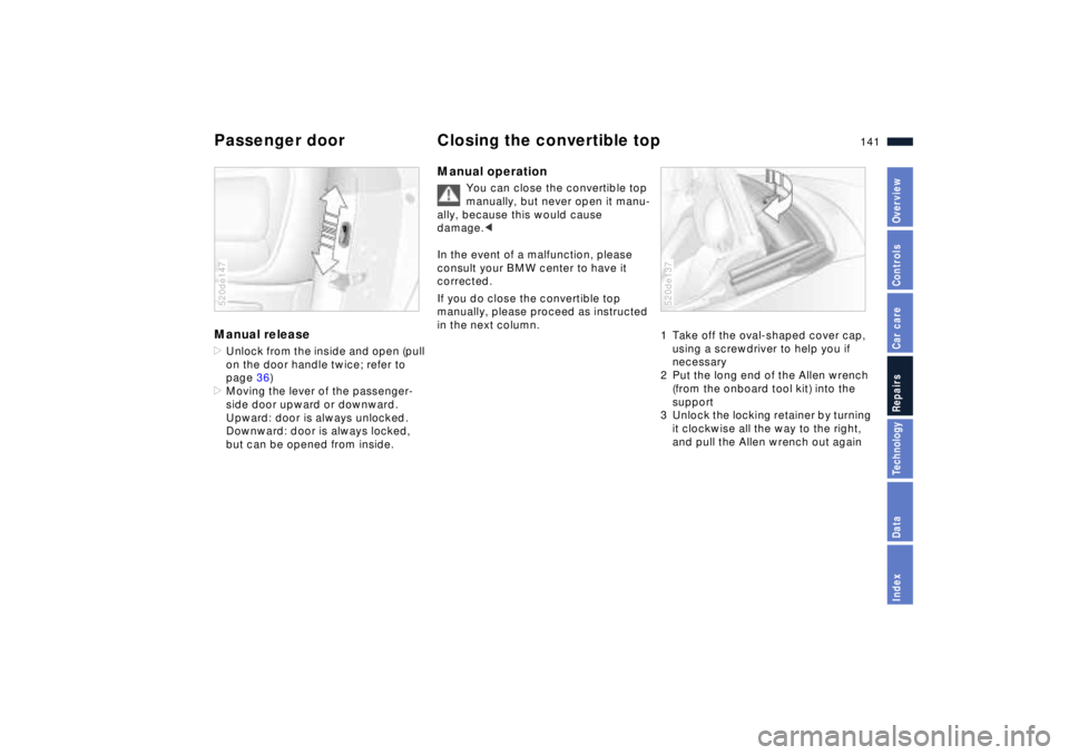
Passenger door Closing the convertible top Manual release>Unlock from the inside and open (pull
on the door handle twice; refer to
page 36)
>Moving the lever of the passenger-
side door upward or downward.
Upward: door is always unlocked.
Downward: door is always locked,
but can be opened from inside.520de147
Manual operation
You can close the convertible top
manually, but never open it manu-
ally, because this would cause
damage.<
In the event of a malfunction, please
consult your BMW center to have it
corrected.
If you do close the convertible top
manually, please proceed as instructed
in the next column.
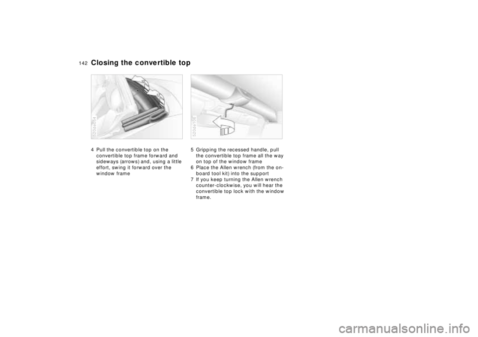
1 Take off the oval-shaped cover cap,
using a screwdriver to help you if
necessary
2 Put the long end of the Allen wrench
(from the onboard tool kit) into the
support
3 Unlock the locking retainer by turning
it clockwise all the way to the right,
and pull the Allen wrench out again 520de137
Page 142 of 170
142n
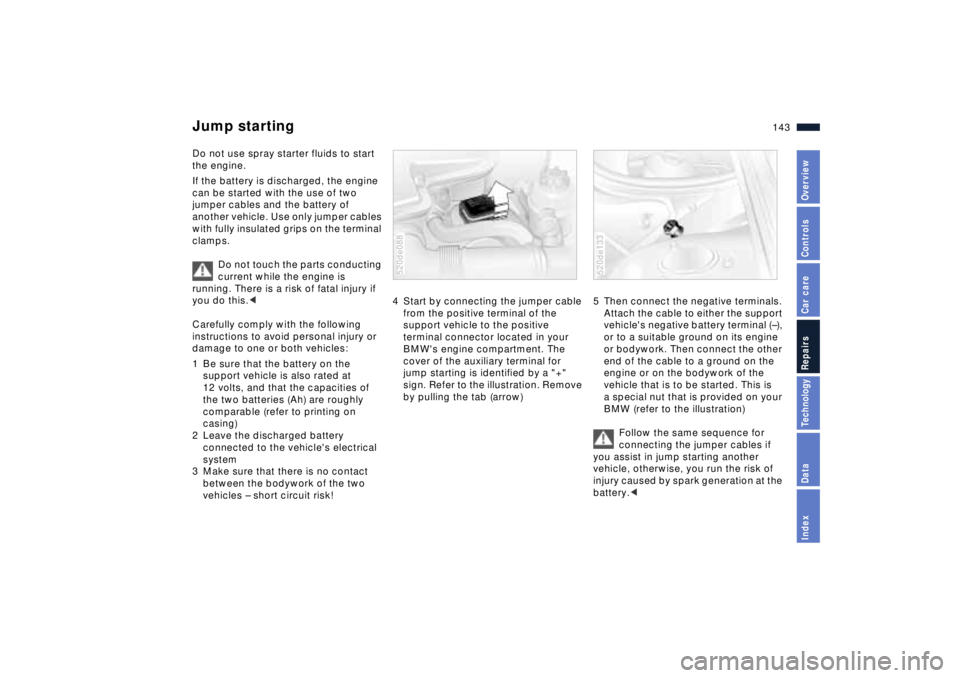
Closing the convertible top 4 Pull the convertible top on the
convertible top frame forward and
sideways (arrows) and, using a little
effort, swing it forward over the
window frame 520de054
5 Gripping the recessed handle, pull
the convertible top frame all the way
on top of the window frame
6 Place the Allen wrench (from the on-
board tool kit) into the support
7 If you keep turning the Allen wrench
counter-clockwise, you will hear the
convertible top lock with the window
frame.520de106
Page 143 of 170
143n
IndexDataTechnologyRepairsCar careControlsOverview
Do not use spray starter fluids to start
the engine.
If the battery is discharged, the engine
can be started with the use of two
jumper cables and the battery of
another vehicle. Use only jumper cables
with fully insulated grips on the terminal
clamps.
Do not touch the parts conducting
current while the engine is
running. There is a risk of fatal injury if
you do this.<
Carefully comply with the following
instructions to avoid personal injury or
damage to one or both vehicles:
1 Be sure that the battery on the
support vehicle is also rated at
12 volts, and that the capacities of
the two batteries (Ah) are roughly
comparable (refer to printing on
casing)
2 Leave the discharged battery
connected to the vehicle's electrical
system
3 Make sure that there is no contact
between the bodywork of the two
vehicles Ð short circuit risk!
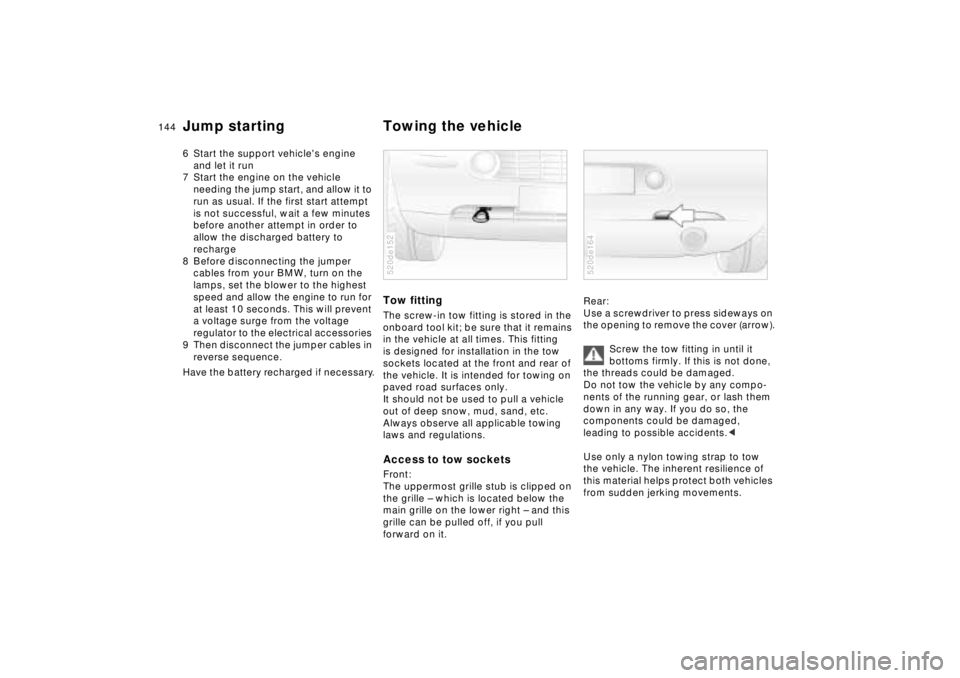
4 Start by connecting the jumper cable
from the positive terminal of the
support vehicle to the positive
terminal connector located in your
BMW's engine compartment. The
cover of the auxiliary terminal for
jump starting is identified by a "+"
sign. Refer to the illustration. Remove
by pulling the tab (arrow) 520de088
5 Then connect the negative terminals.
Attach the cable to either the support
vehicle's negative battery terminal (Ð),
or to a suitable ground on its engine
or bodywork. Then connect the other
end of the cable to a ground on the
engine or on the bodywork of the
vehicle that is to be started. This is
a special nut that is provided on your
BMW (refer to the illustration)
Follow the same sequence for
connecting the jumper cables if
you assist in jump starting another
vehicle, otherwise, you run the risk of
injury caused by spark generation at the
battery.<520de133
Jump starting
Page 144 of 170
144n
Jump starting Towing the vehicle6 Start the support vehicle's engine
and let it run
7 Start the engine on the vehicle
needing the jump start, and allow it to
run as usual. If the first start attempt
is not successful, wait a few minutes
before another attempt in order to
allow the discharged battery to
recharge
8 Before disconnecting the jumper
cables from your BMW, turn on the
lamps, set the blower to the highest
speed and allow the engine to run for
at least 10 seconds. This will prevent
a voltage surge from the voltage
regulator to the electrical accessories
9 Then disconnect the jumper cables in
reverse sequence.
Have the battery recharged if necessary.
Tow fittingThe screw-in tow fitting is stored in the
onboard tool kit; be sure that it remains
in the vehicle at all times. This fitting
is designed for installation in the tow
sockets located at the front and rear of
the vehicle. It is intended for towing on
paved road surfaces only.
It should not be used to pull a vehicle
out of deep snow, mud, sand, etc.
Always observe all applicable towing
laws and regulations.Access to tow socketsFront:
The uppermost grille stub is clipped on
the grille Ð which is located below the
main grille on the lower right Ð and this
grille can be pulled off, if you pull
forward on it.520de152
Rear:
Use a screwdriver to press sideways on
the opening to remove the cover (arrow).
Screw the tow fitting in until it
bottoms firmly. If this is not done,
the threads could be damaged.
Do not tow the vehicle by any compo-
nents of the running gear, or lash them
down in any way. If you do so, the
components could be damaged,
leading to possible accidents.<
Use only a nylon towing strap to tow
the vehicle. The inherent resilience of
this material helps protect both vehicles
from sudden jerking movements.520de164
Page 145 of 170
145n
IndexDataTechnologyRepairsCar careControlsOverview
Towing the vehicle
Avoid "off-center" towing. Be sure
that the tow rope is pulled tightly
when the towing vehicle begins to
move.<
The towed vehicle should always
be the lighter of the two vehicles.
If this is not the case, it is no longer
possible to control vehicle response.<
Tow-startingFor instructions on jump starting, refer
to page 143.
Never attempt to use your vehicle to
push another vehicle, since damage to
the energy-absorbing bumpers could
result.
Towing a vehicle1 Put the manual-shift gear lever in
neutral
2 Towing speed:
Max. 45 mph (70 km/h)
3 Towing distance:
Max. 95 miles (150 km)
4 Leave the ignition key in position 1
to ensure that the brake lamps, turn
signals, horn and windshield wipers
remain operative, and to prevent the
steering lock detent from engaging
5 Switch on the hazard-warning system
(comply with country-specific regula-
tions).
Find some means of identifying the
vehicle in tow, e. g. place a sign or
warning triangle in the rear window.
Make sure that the ignition key
remains in position 1 even
when the electrical system has failed
to prevent the steering lock from
engaging. The steering and brakes are
without power assist when the engine is
not running. This means that increased
effort is required for steering and
braking.<
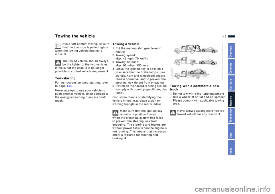
Towing with a commercial tow
truck>Do not tow with sling-type equipment
>Use a wheel lift or flat bed equipment
>Please comply with applicable towing
laws.
Never allow passengers to ride in a
towed vehicle for any reason.<520us014
Page 146 of 170
146n
Page 147 of 170
Overview
Controls and features
Operation, care
and maintenance
Owner service procedures
Technical data
Index Advanced technology
147n
IndexDataTechnologyRepairsCar careControlsOverview
Airbags148
Radio reception148
Dynamic Stability Control
(DSC)149
Safety belt tensioner149
Interior rearview mirror with
automatic dimmer150
Xenon lamps151
Technology
Page 148 of 170
148n
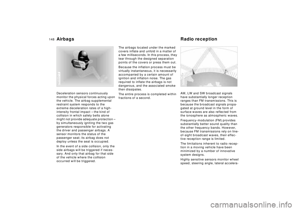
Deceleration sensors continuously
monitor the physical forces acting upon
the vehicle. The airbag supplemental
restraint system responds to the
extreme deceleration rates of a high-
intensity frontal impact Ð the kind of
collision in which safety belts alone
might not provide adequate protection Ð
by simultaneously igniting the two gas
generators responsible for activating
the driver and passenger airbags. A
sensor monitors the status of the
passenger seat; its airbag does not
deploy unless the seat is occupied.
In the event of a side collision, only the
side airbags will be triggered if neces-
sary. And only that airbag for that side
of the vehicle where the collision
occurred will be triggered.
390de012
The airbags located under the marked
covers inflate and unfold in a matter of
a few milliseconds. In this process, they
tear through the designed separation
points of the covers or press them out.
Because the inflation process must be
virtually instantaneous, it is necessarily
accompanied by a certain amount of
ignition and inflation noise. The gas
required to inflate the airbags is not
dangerous, and the associated smoke
then dissipates.
The entire process is completed within
fractions of a second.AM, LW and SW broadcast signals
have substantially longer reception
ranges than FM transmissions. This is
because the broadcast signals propa-
gated at ground level in the form of
surface waves are also reflected from
the ionosphere as atmospheric waves.
Frequency-modulation (FM) provides
substantially better sound quality than
the other frequency bands. However,
because FM transmissions rely on line-
of-sight broadcast waves, their effec-
tive reception range is limited.
The limitations inherent to radio recep-
tion in a moving vehicle have been
minimized by a number of innovative
system designs.
Highly sensitive sensors monitor wheel
speed, steering angle, lateral accelera-
360de084
Airbags Radio reception
Page 149 of 170
149n
IndexDataTechnologyRepairsCar careControlsOverview
tion, braking pressures and the
vehicle's yaw rate around its vertical
axis.
When the system detects substantial
differences in rotation rates between
wheels, it acts to inhibit uncontrolled
wheelspin by reducing the drive torque
transmitted to the affected wheel(s),
while also initiating selective braking
intervention as needed.
In addition, DSC permanently monitors
the vehicle's current operating condi-
tion and compares it with an ideal
status calculated based on sensor
signals. DSC reacts to deviations from
this ideal status such as incipient
understeer or oversteer by instanta-
neously reducing engine torque to
restore vehicle stability. This strategy
can be supplemented by selective
braking intervention, available at all four
wheels. DSC acts to prevent traction
loss and skids before the situation can
become critical.You may need some time to become
accustomed to this system's interven-
tion. However, it provides optimum
drive force and vehicle stability.
The braking intervention may be
accompanied by sounds specific to
the system.
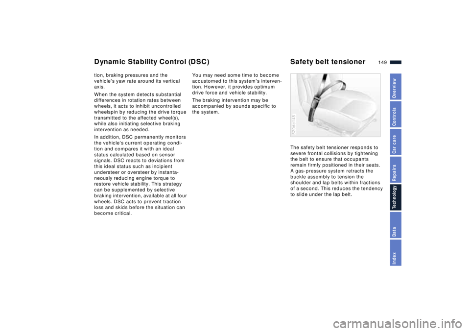
The safety belt tensioner responds to
severe frontal collisions by tightening
the belt to ensure that occupants
remain firmly positioned in their seats.
A gas-pressure system retracts the
buckle assembly to tension the
shoulder and lap belts within fractions
of a second. This reduces the tendency
to slide under the lap belt.
520de148
Dynamic Stability Control (DSC) Safety belt tensioner
Page 150 of 170
150n
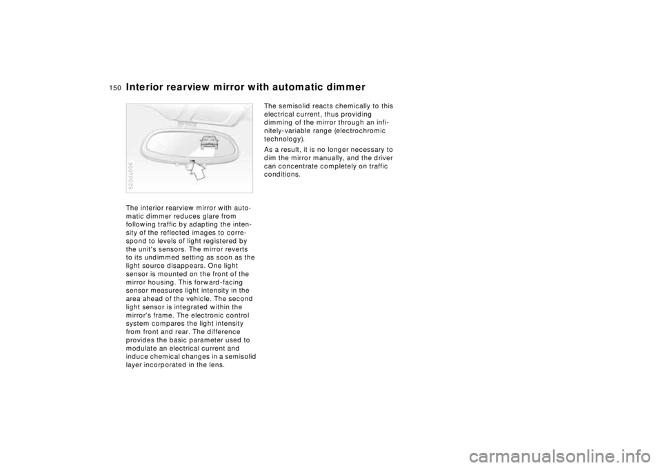
Interior rearview mirror with automatic dimmer The interior rearview mirror with auto-
matic dimmer reduces glare from
following traffic by adapting the inten-
sity of the reflected images to corre-
spond to levels of light registered by
the unit's sensors. The mirror reverts
to its undimmed setting as soon as the
light source disappears. One light
sensor is mounted on the front of the
mirror housing. This forward-facing
sensor measures light intensity in the
area ahead of the vehicle. The second
light sensor is integrated within the
mirror's frame. The electronic control
system compares the light intensity
from front and rear. The difference
provides the basic parameter used to
modulate an electrical current and
induce chemical changes in a semisolid
layer incorporated in the lens.520de096
The semisolid reacts chemically to this
electrical current, thus providing
dimming of the mirror through an infi-
nitely-variable range (electrochromic
technology).
As a result, it is no longer necessary to
dim the mirror manually, and the driver
can concentrate completely on traffic
conditions.