light BUICK ENCLAVE 2010 Owners Manual
[x] Cancel search | Manufacturer: BUICK, Model Year: 2010, Model line: ENCLAVE, Model: BUICK ENCLAVE 2010Pages: 438, PDF Size: 2.47 MB
Page 280 of 438
9-38 Driving and Operating
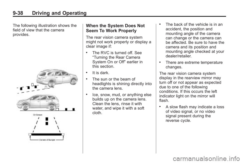
The following illustration shows the
field of view that the camera
provides.When the System Does Not
Seem To Work Properly
The rear vision camera system
might not work properly or display a
clear image if:
.The RVC is turned off. See
“Turning the Rear Camera
System On or Off”earlier in
this section.
.It is dark.
.The sun or the beam of
headlights is shining directly into
the camera lens.
.Ice, snow, mud, or anything else
builds up on the camera lens.
Clean the lens, rinse it with
water, and wipe it with a soft
cloth.
.The back of the vehicle is in an
accident, the position and
mounting angle of the camera
can change or the camera can
be affected. Be sure to have the
camera and its position and
mounting angle checked at your
dealer/retailer.
.There are extreme temperature
changes.
The rear vision camera system
display in the rearview mirror may
turn off or not appear as expected
due to one of the following
conditions. If this occurs the left
indicator light on the mirror will
flash.
.A slow flash may indicate a loss
of video signal, or no video
signal present during the
reverse cycle.
Page 281 of 438

Driving and Operating 9-39
.A fast flash may indicate that the
display has been on for the
maximum allowable time during
a reverse cycle, or the display
has reached an Over
Temperature limit.
The fast flash conditions are
used to protect the video device
from high temperature
conditions. Once conditions
return to normal the device will
reset and the green indicator will
stop flashing.
During any of these fault conditions,
the display will be blank and the
indicator will continue to flash as
long as the vehicle is in R (Reverse)
or until the conditions return to
normal.
Pressing and holding
zwhen the
left indicator light is flashing will turn
off the video display along with the
left indicator light.
Fuel
Use of the recommended fuel is an
important part of the proper
maintenance of this vehicle. To help
keep the engine clean and maintain
optimum vehicle performance, we
recommend the use of gasoline
advertised as TOP TIER Detergent
Gasoline.
Look for the TOP TIER label on the
fuel pump to ensure gasoline meets
enhanced detergency standards
developed by auto companies. A list
of marketers providing TOP TIER
Detergent Gasoline can be found at
www.toptiergas.com.
Page 285 of 438

Driving and Operating 9-43
While refueling, hang the tethered
fuel cap from the hook on the
fuel door.
{WARNING
Fuel can spray out on you if you
open the fuel cap too quickly.
If you spill fuel and then
something ignites it, you could be
badly burned. This spray can
happen if the tank is nearly full,
and is more likely in hot weather.
Open the fuel cap slowly and wait
for any hiss noise to stop. Then
unscrew the cap all the way.Be careful not to spill fuel. Do not
top off or overfill the tank and wait a
few seconds after you have finished
pumping before removing the
nozzle. Clean fuel from painted
surfaces as soon as possible.
See
Exterior Care on page 10‑88.
When replacing the fuel cap,
turn it clockwise until it clicks.
Make sure the cap is fully installed.
The diagnostic system can
determine if the fuel cap has been
left off or improperly installed. This
would allow fuel to evaporate into
the atmosphere. See Malfunction
Indicator Lamp on page 5‑18.
{WARNING
If a fire starts while you are
refueling, do not remove the
nozzle. Shut off the flow of fuel by
shutting off the pump or by
notifying the station attendant.
Leave the area immediately.
Notice: If a new fuel cap is
needed, be sure to get the right
type of cap from your dealer/
retailer. The wrong type fuel cap
might not fit properly, might
cause the malfunction indicator
lamp to light, and could damage
the fuel tank and emissions
system. See Malfunction Indicator
Lamp on page 5‑18.
Page 289 of 438
Driving and Operating 9-47
Tow/Haul Mode
Tow/Haul assists when pulling a
heavy trailer or a large or heavy
load. The purpose of the Tow/Haul
mode is to:
.Reduce the frequency and
improve the predictability of
transmission shifts.
.Provide the same solid shift feel
as when the vehicle is unloaded.
.Improve control of vehicle speed
while requiring less throttle pedal
activity.
.Increase the charging system
voltage to assist in recharging a
battery installed in a trailer.
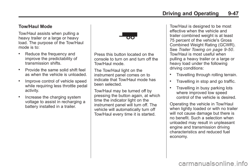
Press this button located on the
console to turn on and turn off the
Tow/Haul mode.
The Tow/Haul light on the
instrument panel comes on to
indicate that Tow/Haul mode has
been selected.
Tow/Haul may be turned off by
pressing the button again, at which
time the indicator light on the
instrument panel will turn off. The
vehicle will automatically turn off
Tow/Haul every time it is started.Tow/Haul is designed to be most
effective when the vehicle and
trailer combined weight is at least
75 percent of the vehicle's Gross
Combined Weight Rating (GCWR).
See
Trailer Towing
on page 9‑50.
Tow/Haul is most useful when
pulling a heavy trailer or a large or
heavy load under the following
driving conditions:
.Travelling through rolling terrain.
.Travelling in stop and go traffic.
.Travelling in busy parking lots
where improved low speed
control of the vehicle is desired.
Operating the vehicle in Tow/Haul
when lightly loaded or with no trailer
will not cause damage but there is
no benefit. Such a selection when
unloaded may result in unpleasant
engine and transmission driving
characteristics and reduced fuel
economy.
Page 296 of 438

9-54 Driving and Operating
Weight-Distributing Hitches and
Weight Carrying Hitches
A. Body-to-Ground Distance
B. Front of Vehicle
When using a weight-distributing
hitch, the hitch must be adjusted so
that the distance (A) remains the
same both before and after coupling
the trailer to the tow vehicle.
Safety Chains
Always attach chains between the
vehicle and the trailer. Cross the
safety chains under the tongue of
the trailer to help prevent the tongue
from contacting the road if it
becomes separated from the hitch.
Always leave just enough slack so
the rig can turn. Never allow safety
chains to drag on the ground.
Trailer Brakes
A loaded trailer that weighs more
than 450 kg (1,000 lbs) needs to
have its own brake system that is
adequate for the weight of the
trailer. Be sure to read and follow
the instructions for the trailer brakes
so they are installed, adjusted and
maintained properly.
Because the vehicle has antilock
brakes, do not try to tap into the
vehicle's hydraulic brake system.
If you do, both brake systems will
not work well, or at all.
Trailer Wiring Harness
Basic Trailer Wiring
The trailer wiring harness, with a
seven-pin connector, is located at
the rear of the vehicle and is tied to
the vehicle's frame. The harness
connector can be plugged into a
seven-pin universal heavy-duty
trailer connector available through
your dealer/retailer.
The seven-wire harness contains
the following trailer circuits:
.Yellow: Left Stop/Turn Signal
.Dark Green: Right Stop/Turn
Signal
.Brown: Taillamps
.Black: Ground
.Light Green: Back-up Lamps
.Red/Black: Battery Feed
.Dark Blue: Trailer Brake*
*The fuse for this circuit is installed
in the underhood electrical center,
but the wires are not connected.
Page 297 of 438

Driving and Operating 9-55
They should be connected by your
dealer/retailer or a qualified service
center.
If the back-up lamp circuit is not
functional, contact your dealer/
retailer.
If a remote (non-vehicle) battery is
being charged, press the Tow/Haul
mode switch located on the center
console near the climate controls.
This will boost the vehicle system
voltage and properly charge the
battery. If the trailer is too light for
Tow/Haul mode, turn on the
headlamps (Non-HID only) as a
second way to boost the vehicle
system and charge the battery.Electric Trailer Brake Control
Wiring Provisions
These wiring provisions for an
electric trailer brake controller are
included with the vehicle as part of
the trailer wiring package. The
instrument panel contains blunt cut
wires behind the steering column for
the electric trailer brake controller.
The harness contains the following
wires:
.Red/Black: Power Supply
.White: Brake Switch Signal
.Gray: Illumination
.Dark Blue: Trailer Brake Signal
.Black: Ground
The electric trailer brake controller
should be installed by your dealer/
retailer or a qualified service center.
Conversions and
Add-Ons
Add-On Electrical
Equipment
Notice: Do not add anything
electrical to the vehicle unless
you check with your dealer/
retailer first. Some electrical
equipment can damage the
vehicle and the damage would
not be covered by the vehicle's
warranty. Some add-on electrical
equipment can keep other
components from working as
they should.
Add-on equipment can drain the
vehicle battery, even if the vehicle is
not operating.
The vehicle has an airbag system.
Before attempting to add anything
electrical to the vehicle, see
Servicing the Airbag-Equipped
Vehicle
on page 3‑41and Adding
Equipment to the Airbag-Equipped
Vehicle on page 3‑42.
Page 299 of 438
Vehicle Care 10-1
Vehicle Care
General Information
General Information . . . . . . . . . . 10-2
California Proposition65 Warning . . . . . . . . . . . . . . . . . 10-3
California Perchlorate Materials Requirements . . . . 10-3
Accessories and Modifications . . . . . . . . . . . . . . . 10-3
Vehicle Checks
Doing Your OwnService Work . . . . . . . . . . . . . . . 10-4
Hood . . . . . . . . . . . . . . . . . . . . . . . . 10-4
Engine Compartment Overview . . . . . . . . . . . . . . . . . . . 10-6
Engine Cover . . . . . . . . . . . . . . . . 10-7
Engine Oil . . . . . . . . . . . . . . . . . . . 10-8
Engine Oil Life System . . . . . 10-10
Automatic Transmission Fluid . . . . . . . . . . . . . . . . . . . . . . 10-11
Engine Air Cleaner/Filter . . . . 10-12
Cooling System . . . . . . . . . . . . 10-14
Engine Coolant . . . . . . . . . . . . . 10-14
Engine Overheating . . . . . . . . 10-18 Overheated Engine
Protection
Operating Mode . . . . . . . . . . . 10-20
Power Steering Fluid . . . . . . . 10-20
Washer Fluid . . . . . . . . . . . . . . . 10-21
Brakes . . . . . . . . . . . . . . . . . . . . . 10-22
Brake Fluid . . . . . . . . . . . . . . . . . 10-23
Battery . . . . . . . . . . . . . . . . . . . . . 10-25
All-Wheel Drive . . . . . . . . . . . . . 10-25
Starter Switch Check . . . . . . . 10-25
Automatic Transmission Shift Lock Control System
Check . . . . . . . . . . . . . . . . . . . . . 10-26
Ignition Transmission Lock Check . . . . . . . . . . . . . . . . . . . . . 10-26
Park Brake and P (Park) Mechanism Check . . . . . . . . 10-26
Wiper Blade Replacement . . . . . . . . . . . . . . 10-27
Windshield Replacement . . . 10-28
Headlamp Aiming
Headlamp Aiming . . . . . . . . . . 10-28
Bulb Replacement
Bulb Replacement . . . . . . . . . . 10-28
Halogen Bulbs . . . . . . . . . . . . . . 10-28
High Intensity Discharge (HID) Lighting . . . . . . . . . . . . . 10-29 Taillamps, Turn Signal,
Sidemarker, and
Stoplamps . . . . . . . . . . . . . . . . 10-29
License Plate Lamp . . . . . . . . 10-30
Replacement Bulbs . . . . . . . . . 10-30
Electrical System
High Voltage Devices and Wiring . . . . . . . . . . . . . . . . . . . . . 10-30
Electrical System Overload . . . . . . . . . . . . . . . . . . 10-31
Fuses and Circuit Breakers . . . . . . . . . . . . . . . . . . 10-31
Engine Compartment Fuse Block . . . . . . . . . . . . . . . . . . . . . 10-31
Instrument Panel Fuse Block . . . . . . . . . . . . . . . . . . . . . 10-35
Wheels and Tires
Tires . . . . . . . . . . . . . . . . . . . . . . . . 10-37
Tire Sidewall Labeling . . . . . . 10-38
Tire Designations . . . . . . . . . . . 10-40
Tire Terminology and
Definitions . . . . . . . . . . . . . . . . 10-41
Tire Pressure . . . . . . . . . . . . . . . 10-44
Tire Pressure Monitor System . . . . . . . . . . . . . . . . . . . 10-45
Tire Pressure Monitor Operation . . . . . . . . . . . . . . . . . 10-46
Page 310 of 438
10-12 Vehicle Care
Notice:Use of the incorrect
automatic transmission fluid may
damage the vehicle, and the
damages may not be covered by
the vehicle's warranty. Always
use the automatic transmission
fluid listed in Recommended
Fluids and Lubricants
on
page 11‑7.
The transmission fluid will not reach
the end of the dipstick unless the
transmission is at operating
temperature. If you need to check
the transmission fluid level, please
take the vehicle to your dealer/
retailer.
Engine Air Cleaner/Filter
When to Inspect the Engine Air
Cleaner/Filter
Inspect the air cleaner/filter at the
Maintenance IIintervals and replace
it at the first oil change after each
80 000 km (50,000 mile) interval.
See Scheduled Maintenance
on
page 11‑2for more information.
If you are driving in dusty/dirty
conditions, inspect the filter at each
engine oil change.
See Engine Compartment Overview
on page 10‑6for the location of the
engine air cleaner/filter.
How to Inspect the Engine Air
Cleaner/Filter
To inspect the air cleaner/filter,
remove the filter from the vehicle
and lightly shake the filter (away
from vehicle) to release loose dust
and dirt. If the filter remains caked
with dirt, a new filter is required. To inspect or replace the engine air
cleaner/filter:
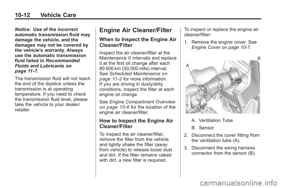
1. Remove the engine cover. See
Engine Cover on page 10‑7.
A. Ventilation Tube
B. Sensor
2. Disconnect the cover fitting from the ventilation tube (A).
3. Disconnect the wiring harness connector from the sensor (B).
Page 316 of 438

10-18 Vehicle Care
6. Fill the coolant recovery tank tothe FULL COLD mark.
7. Reinstall the cap on the coolant recovery tank but leave the
radiator pressure cap off.8. Start the engine and let it rununtil the upper radiator hose
feels warm. Any time during this
procedure, watch out for the
engine cooling fan(s).
9. If the coolant level inside the radiator filler neck is low, add
more of the proper DEX-COOL
coolant mixture through the filler
neck until the level is back up to
the base of the filler neck.
Replace the pressure cap. Be
sure to secure it tightly. Notice:
If the pressure cap is not
tightly installed, coolant loss and
possible engine damage may
occur. Be sure the cap is properly
and tightly secured.
Engine Overheating
The vehicle has several indicators
to warn of engine overheating.
There is an engine coolant
temperature gage on the instrument
panel cluster. See Engine Coolant
Temperature Gage on page 5‑15.
The vehicle may also display an
ENGINE OVERHEATED IDLE
ENGINE and ENGINE
OVERHEATED STOP ENGINE
message in the Driver Information
Center (DIC). See Warning Lights,
Gages, and Indicators
on
page 5‑12.
You may decide not to lift the hood
when this warning appears, but
instead get service help right away.
See Roadside Assistance Program
on page 13‑6.
Page 321 of 438
Vehicle Care 10-23
Some driving conditions or climates
can cause a brake squeal when the
brakes are first applied or lightly
applied. This does not mean
something is wrong with the brakes.
Properly torqued wheel nuts are
necessary to help prevent brake
pulsation. When tires are rotated,
inspect brake pads for wear and
evenly tighten wheel nuts in the
proper sequence to torque
specifications inCapacities and
Specifications on page 12‑2.
Brake linings should always be
replaced as complete axle sets.
Brake Pedal Travel
See your dealer/retailer if the brake
pedal does not return to normal
height, or if there is a rapid increase
in pedal travel. This could be a sign
that brake service might be
required.
Brake Adjustment
Every time the brakes are applied,
with or without the vehicle moving,
the brakes adjust for wear.
Replacing Brake System Parts
The braking system on a vehicle is
complex. Its many parts have to be
of top quality and work well together
if the vehicle is to have really good
braking. The vehicle was designed
and tested with top-quality brake
parts. When parts of the braking
system are replaced, be sure to get
new, approved replacement parts.
If this is not done, the brakes might
not work properly. For example,
installing disc brake pads that are
wrong for the vehicle, can change
the balance between the front and
rear brakes —for the worse. The
braking performance expected can
change in many other ways if the
wrong replacement brake parts are
installed.
Brake Fluid
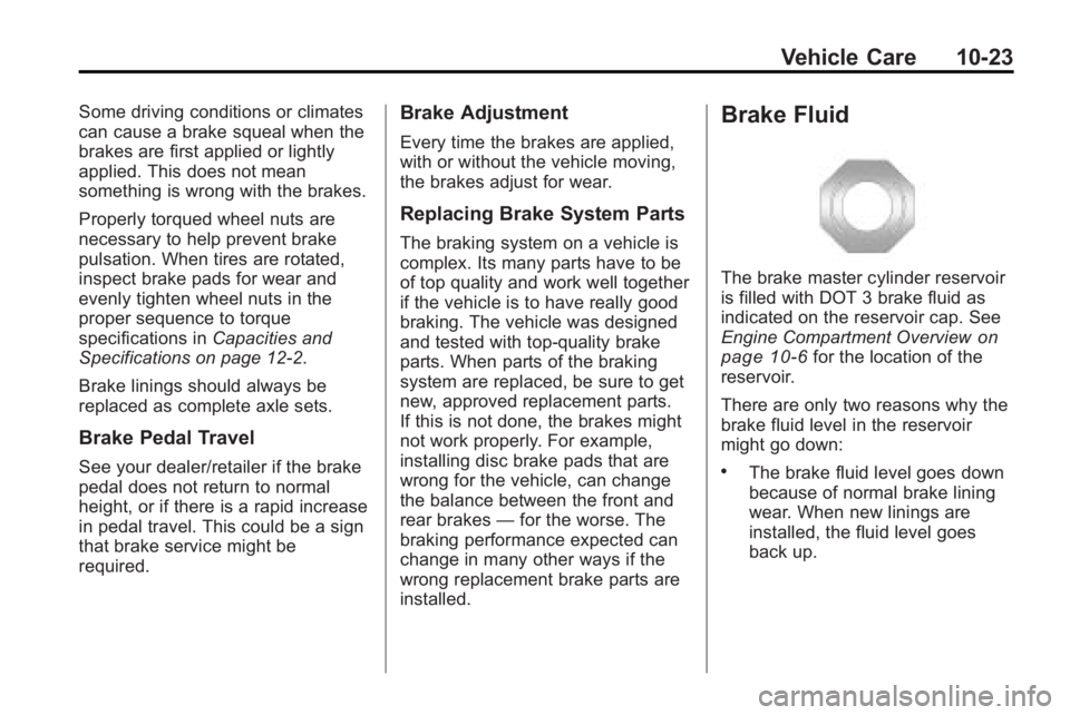
The brake master cylinder reservoir
is filled with DOT 3 brake fluid as
indicated on the reservoir cap. See
Engine Compartment Overview
on
page 10‑6for the location of the
reservoir.
There are only two reasons why the
brake fluid level in the reservoir
might go down:
.The brake fluid level goes down
because of normal brake lining
wear. When new linings are
installed, the fluid level goes
back up.