warning light BUICK ENCLAVE 2010 Service Manual
[x] Cancel search | Manufacturer: BUICK, Model Year: 2010, Model line: ENCLAVE, Model: BUICK ENCLAVE 2010Pages: 438, PDF Size: 2.47 MB
Page 273 of 438

Driving and Operating 9-31
The cruise control buttons are
located on left side of the steering
wheel.
T(On/Off):Press to turn cruise
control on and off. The indicator
comes on when cruise control is on.
+ RES (Resume/Accelerate):
Press to make the vehicle
accelerate or resume to a previously
set speed.
SET– :Press to set the speed or
make the vehicle decelerate.
[(Cancel): Press to cancel cruise
control. Setting Cruise Control
Cruise control will not work if the
parking brake is set, or if the master
cylinder brake fluid level is low.
The cruise control light on the
instrument panel cluster comes on
after the cruise control has been set
to the desired speed.
{WARNING
If you leave your cruise control on
when you are not using cruise,
you might hit a button and go into
cruise when you do not want to.
You could be startled and even
lose control. Keep the cruise
control switch off until you want to
use cruise control.
1. Press the
Ibutton.
2. Get up to the speed desired. 3. Press and release the
SET– button located on the
steering wheel.
4. Take your foot off the accelerator.
Resuming a Set Speed
If the cruise control is set at a
desired speed and then the brakes
are applied, the cruise control is
disengaged. But it does not need to
be reset.
Once the vehicle speed is 40 km/h
(25 mph) or greater, press the
+RES button on the steering wheel.
The vehicle returns to the previously
set speed and stays there.
Page 277 of 438
Driving and Operating 9-35
WARNING (Continued)
Your judged distances using the
screen will differ from actual
distances.
So if you do not use proper care
before backing up, you could hit a
vehicle, child, pedestrian,
bicyclist, or pet, resulting in
vehicle damage, injury, or death.
Even though the vehicle has the
RVC system, always check
carefully before backing up by
checking behind and around the
vehicle.
Vehicles Without Navigation
System
The rear vision camera system is
designed to help the driver when
backing up by displaying a view of
the area behind the vehicle. When
the key is in the ON/RUN position
and the driver shifts the vehicle into
R (Reverse), the video image
automatically appears on the inside
rear view mirror. Once the driver
shifts out of R (Reverse), the video
image automatically disappears
from the inside rear view mirror.
Turning the Rear Vision Camera
System Off or On
To turn off the rear vision camera
system, press and hold
z, located
on the inside rearview mirror, until
the left indicator light turns off. The
rear camera vision display is now
disabled. To turn the rear vision camera
system on again, press and
hold
zuntil the left indicator light
illuminates. The rear vision camera
system display is now enabled and
the display will appear in the mirror
normally.
Vehicles With Navigation
System
The rear vision camera system is
designed to help the driver when
backing up by displaying a view of
the area behind the vehicle. When
the driver shifts the vehicle into
R (Reverse), the video image
automatically appears on the
navigation screen. Once the driver
shifts out of R (Reverse), the
navigation screen will go back to the
last screen that had been displayed,
after a delay.
Page 285 of 438

Driving and Operating 9-43
While refueling, hang the tethered
fuel cap from the hook on the
fuel door.
{WARNING
Fuel can spray out on you if you
open the fuel cap too quickly.
If you spill fuel and then
something ignites it, you could be
badly burned. This spray can
happen if the tank is nearly full,
and is more likely in hot weather.
Open the fuel cap slowly and wait
for any hiss noise to stop. Then
unscrew the cap all the way.Be careful not to spill fuel. Do not
top off or overfill the tank and wait a
few seconds after you have finished
pumping before removing the
nozzle. Clean fuel from painted
surfaces as soon as possible.
See
Exterior Care on page 10‑88.
When replacing the fuel cap,
turn it clockwise until it clicks.
Make sure the cap is fully installed.
The diagnostic system can
determine if the fuel cap has been
left off or improperly installed. This
would allow fuel to evaporate into
the atmosphere. See Malfunction
Indicator Lamp on page 5‑18.
{WARNING
If a fire starts while you are
refueling, do not remove the
nozzle. Shut off the flow of fuel by
shutting off the pump or by
notifying the station attendant.
Leave the area immediately.
Notice: If a new fuel cap is
needed, be sure to get the right
type of cap from your dealer/
retailer. The wrong type fuel cap
might not fit properly, might
cause the malfunction indicator
lamp to light, and could damage
the fuel tank and emissions
system. See Malfunction Indicator
Lamp on page 5‑18.
Page 299 of 438
Vehicle Care 10-1
Vehicle Care
General Information
General Information . . . . . . . . . . 10-2
California Proposition65 Warning . . . . . . . . . . . . . . . . . 10-3
California Perchlorate Materials Requirements . . . . 10-3
Accessories and Modifications . . . . . . . . . . . . . . . 10-3
Vehicle Checks
Doing Your OwnService Work . . . . . . . . . . . . . . . 10-4
Hood . . . . . . . . . . . . . . . . . . . . . . . . 10-4
Engine Compartment Overview . . . . . . . . . . . . . . . . . . . 10-6
Engine Cover . . . . . . . . . . . . . . . . 10-7
Engine Oil . . . . . . . . . . . . . . . . . . . 10-8
Engine Oil Life System . . . . . 10-10
Automatic Transmission Fluid . . . . . . . . . . . . . . . . . . . . . . 10-11
Engine Air Cleaner/Filter . . . . 10-12
Cooling System . . . . . . . . . . . . 10-14
Engine Coolant . . . . . . . . . . . . . 10-14
Engine Overheating . . . . . . . . 10-18 Overheated Engine
Protection
Operating Mode . . . . . . . . . . . 10-20
Power Steering Fluid . . . . . . . 10-20
Washer Fluid . . . . . . . . . . . . . . . 10-21
Brakes . . . . . . . . . . . . . . . . . . . . . 10-22
Brake Fluid . . . . . . . . . . . . . . . . . 10-23
Battery . . . . . . . . . . . . . . . . . . . . . 10-25
All-Wheel Drive . . . . . . . . . . . . . 10-25
Starter Switch Check . . . . . . . 10-25
Automatic Transmission Shift Lock Control System
Check . . . . . . . . . . . . . . . . . . . . . 10-26
Ignition Transmission Lock Check . . . . . . . . . . . . . . . . . . . . . 10-26
Park Brake and P (Park) Mechanism Check . . . . . . . . 10-26
Wiper Blade Replacement . . . . . . . . . . . . . . 10-27
Windshield Replacement . . . 10-28
Headlamp Aiming
Headlamp Aiming . . . . . . . . . . 10-28
Bulb Replacement
Bulb Replacement . . . . . . . . . . 10-28
Halogen Bulbs . . . . . . . . . . . . . . 10-28
High Intensity Discharge (HID) Lighting . . . . . . . . . . . . . 10-29 Taillamps, Turn Signal,
Sidemarker, and
Stoplamps . . . . . . . . . . . . . . . . 10-29
License Plate Lamp . . . . . . . . 10-30
Replacement Bulbs . . . . . . . . . 10-30
Electrical System
High Voltage Devices and Wiring . . . . . . . . . . . . . . . . . . . . . 10-30
Electrical System Overload . . . . . . . . . . . . . . . . . . 10-31
Fuses and Circuit Breakers . . . . . . . . . . . . . . . . . . 10-31
Engine Compartment Fuse Block . . . . . . . . . . . . . . . . . . . . . 10-31
Instrument Panel Fuse Block . . . . . . . . . . . . . . . . . . . . . 10-35
Wheels and Tires
Tires . . . . . . . . . . . . . . . . . . . . . . . . 10-37
Tire Sidewall Labeling . . . . . . 10-38
Tire Designations . . . . . . . . . . . 10-40
Tire Terminology and
Definitions . . . . . . . . . . . . . . . . 10-41
Tire Pressure . . . . . . . . . . . . . . . 10-44
Tire Pressure Monitor System . . . . . . . . . . . . . . . . . . . 10-45
Tire Pressure Monitor Operation . . . . . . . . . . . . . . . . . 10-46
Page 316 of 438

10-18 Vehicle Care
6. Fill the coolant recovery tank tothe FULL COLD mark.
7. Reinstall the cap on the coolant recovery tank but leave the
radiator pressure cap off.8. Start the engine and let it rununtil the upper radiator hose
feels warm. Any time during this
procedure, watch out for the
engine cooling fan(s).
9. If the coolant level inside the radiator filler neck is low, add
more of the proper DEX-COOL
coolant mixture through the filler
neck until the level is back up to
the base of the filler neck.
Replace the pressure cap. Be
sure to secure it tightly. Notice:
If the pressure cap is not
tightly installed, coolant loss and
possible engine damage may
occur. Be sure the cap is properly
and tightly secured.
Engine Overheating
The vehicle has several indicators
to warn of engine overheating.
There is an engine coolant
temperature gage on the instrument
panel cluster. See Engine Coolant
Temperature Gage on page 5‑15.
The vehicle may also display an
ENGINE OVERHEATED IDLE
ENGINE and ENGINE
OVERHEATED STOP ENGINE
message in the Driver Information
Center (DIC). See Warning Lights,
Gages, and Indicators
on
page 5‑12.
You may decide not to lift the hood
when this warning appears, but
instead get service help right away.
See Roadside Assistance Program
on page 13‑6.
Page 322 of 438
10-24 Vehicle Care
.A fluid leak in the brake
hydraulic system can also cause
a low fluid level. Have the brake
hydraulic system fixed, since a
leak means that sooner or later
the brakes will not work well.
Do not top off the brake fluid.
Adding fluid does not correct a leak.
If fluid is added when the linings are
worn, there will be too much fluid
when new brake linings are
installed. Add or remove brake fluid,
as necessary, only when work is
done on the brake hydraulic system.
{WARNING
If too much brake fluid is added, it
can spill on the engine and burn,
if the engine is hot enough. You
or others could be burned, and
the vehicle could be damaged.
Add brake fluid only when work is
done on the brake hydraulic
system. When the brake fluid falls to a low
level, the brake warning light comes
on. See
Brake System Warning
Light on page 5‑21.
What to Add
Use only new DOT 3 brake fluid
from a sealed container. See
Recommended Fluids and
Lubricants on page 11‑7.
Always clean the brake fluid
reservoir cap and the area around
the cap before removing it. This
helps keep dirt from entering the
reservoir.{WARNING
With the wrong kind of fluid in the
brake hydraulic system, the
brakes might not work well. This
could cause a crash. Always use
the proper brake fluid. Notice:
.Using the wrong fluid can
badly damage brake
hydraulic system parts. For
example, just a few drops of
mineral-based oil, such as
engine oil, in the brake
hydraulic system can
damage brake hydraulic
system parts so badly that
they will have to be replaced.
Do not let someone put in
the wrong kind of fluid.
.If brake fluid is spilled on
the vehicle's painted
surfaces, the paint finish can
be damaged. Be careful not
to spill brake fluid on the
vehicle. If you do, wash it off
immediately.
Page 327 of 438
Vehicle Care 10-29
High Intensity Discharge
(HID) Lighting
{WARNING
The low beam high intensity
discharge lighting system
operates at a very high voltage.
If you try to service any of the
system components, you could be
seriously injured. Have your
dealer/retailer or a qualified
technician service them.
The up–level vehicle has HID
headlamps. The park lamp function
is also a function of the HID
headlamp. After an HID headlamp
bulb has been replaced, the beam
might be a slightly different shade
than it was originally. This is normal.
Taillamps, Turn Signal,
Sidemarker, and
Stoplamps
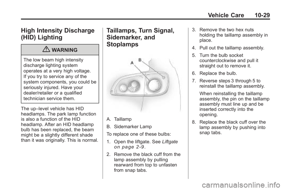
A. Taillamp
B. Sidemarker Lamp
To replace one of these bulbs:
1. Open the liftgate. See Liftgate
on page 2‑9.
2. Remove the black cuff from the lamp assembly by pulling
rearward from top to unfasten
from snap tabs. 3. Remove the two hex nuts
holding the taillamp assembly in
place.
4. Pull out the taillamp assembly.
5. Turn the bulb socket counterclockwise and pull it
straight out to remove it.
6. Replace the bulb.
7. Reverse steps 3 through 5 to reinstall the taillamp assembly.
When reinstalling the taillamp
assembly, the pin on the taillamp
assembly must line up and be
inserted correctly into the
opening.
8. Replace the black cuff over the lamp assembly by pushing into
snap tabs.
Page 344 of 438
10-46 Vehicle Care
Please note that the TPMS is
not a substitute for proper tire
maintenance, and it is the driver's
responsibility to maintain correct tire
pressure, even if under-inflation has
not reached the level to trigger
illumination of the TPMS low tire
pressure telltale.
Your vehicle has also been
equipped with a TPMS malfunction
indicator to indicate when the
system is not operating properly.
The TPMS malfunction indicator is
combined with the low tire pressure
telltale. When the system detects a
malfunction, the telltale will flash for
approximately one minute and then
remain continuously illuminated.
This sequence will continue upon
subsequent vehicle start-ups as
long as the malfunction exists.
When the malfunction indicator is
illuminated, the system may not
be able to detect or signal low
tire pressure as intended.TPMS malfunctions may occur for a
variety of reasons, including the
installation of replacement or
alternate tires or wheels on the
vehicle that prevent the TPMS from
functioning properly. Always check
the TPMS malfunction telltale after
replacing one or more tires or
wheels on your vehicle to ensure
that the replacement or alternate
tires and wheels allow the TPMS to
continue to function properly.
See
Tire Pressure Monitor
Operation
on page 10‑46for
additional information.
Federal Communications
Commission (FCC) and
Industry and Science Canada
See Radio Frequency Statementon
page 13‑16for information
regarding Part 15 of the Federal
Communications Commission (FCC)
Rules and RSS-210/211 of Industry
and Science Canada.
Tire Pressure Monitor
Operation
This vehicle may have a Tire
Pressure Monitor System (TPMS).
The TPMS is designed to warn the
driver when a low tire pressure
condition exists. TPMS sensors are
mounted onto each tire and wheel
assembly, excluding the spare tire
and wheel assembly, if the vehicle
has one. The TPMS sensors
monitor the air pressure in the
vehicle's tires and transmits the tire
pressure readings to a receiver
located in the vehicle.
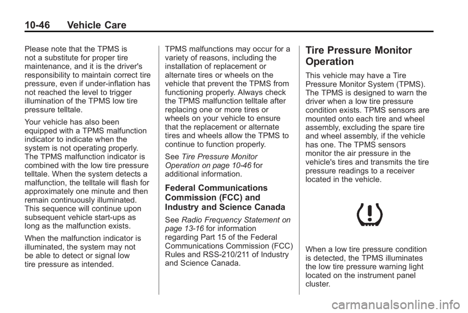
When a low tire pressure condition
is detected, the TPMS illuminates
the low tire pressure warning light
located on the instrument panel
cluster.
Page 345 of 438

Vehicle Care 10-47
At the same time a message to
check the pressure in a specific tire
appears on the Driver Information
Center (DIC) display. The low tire
pressure warning light and the DIC
warning message come on at each
ignition cycle until the tires are
inflated to the correct inflation
pressure. Using the DIC, tire
pressure levels can be viewed by
the driver. For additional information
and details about the DIC operation
and displays seeDriver Information
Center (DIC)
on page 5‑25and
Tire Messages on page 5‑37.
The low tire pressure warning light
may come on in cool weather when
the vehicle is first started, and then
turn off as you start to drive. This
could be an early indicator that the
air pressure in the tire(s) are getting
low and need to be inflated to the
proper pressure. A Tire and Loading Information
label, attached to your vehicle,
shows the size of your vehicle's
original equipment tires and the
correct inflation pressure for your
vehicle's tires when they are cold.
See
Vehicle Load Limits
on
page 9‑12, for an example of the
Tire and Loading Information label
and its location on your vehicle.
Also see Tire Pressure
on
page 10‑44.
Your vehicle's TPMS can warn you
about a low tire pressure condition
but it does not replace normal tire
maintenance. See Tire Inspection
on page 10‑50,Tire Rotationon
page 10‑50and Tires on
page 10‑37. Notice:
Using non-approved tire
sealants could damage the Tire
Pressure Monitor System (TPMS)
sensors. TPMS sensor damage
caused by using an incorrect tire
sealant is not covered by the
vehicle warranty. Always use the
GM approved tire sealant
available through your dealer/
retailer.
Factory-installed Tire Inflator Kits
use a GM approved liquid tire
sealant. Using non-approved tire
sealants could damage the TPMS
sensors. See Tire Sealant and
Compressor Kit
on page 10‑60for
information regarding the inflator kit
materials and instructions.
Page 346 of 438
10-48 Vehicle Care
TPMS Malfunction Light and
Message
The TPMS will not function properly
if one or more of the TPMS sensors
are missing or inoperable. When the
system detects a malfunction, the
low tire warning light flashes for
about one minute and then stays on
for the remainder of the ignition
cycle. A DIC warning message is
also displayed. The low tire warning
light and DIC warning message
come on at each ignition cycle until
the problem is corrected. Some of
the conditions that can cause the
malfunction light and DIC message
to come on are:
.One of the road tires has been
replaced with the spare tire,
if your vehicle has one. The
spare tire does not have a
TPMS sensor. The TPMS
malfunction light and DIC
message should go off once you
re-install the road tire containing
the TPMS sensor.
.The TPMS sensor matching
process was started but not
completed or not completed
successfully after rotating the
vehicle's tires. The DIC message
and TPMS malfunction light
should go off once the TPMS
sensor matching process is
performed successfully. See
“TPMS Sensor Matching
Process”later in this section.
.One or more TPMS sensors are
missing or damaged. The DIC
message and the TPMS
malfunction light should go off
when the TPMS sensors are
installed and the sensor
matching process is performed
successfully. See your dealer/
retailer for service.
.Replacement tires or wheels do
not match your vehicle's original
equipment tires or wheels. Tires
and wheels other than those
recommended for your vehicle
could prevent the TPMS from
functioning properly. See Buying
New Tires on page 10‑52.
.Operating electronic devices or
being near facilities using radio
wave frequencies similar to the
TPMS could cause the TPMS
sensors to malfunction.
If the TPMS is not functioning it
cannot detect or signal a low tire
condition. See your dealer/retailer
for service if the TPMS malfunction
light and DIC message comes on
and stays on.
TPMS Sensor Matching
Process
Each TPMS sensor has a unique
identification code. Any time you
rotate your vehicle's tires or replace
one or more of the TPMS sensors,
the identification codes will need to
be matched to the new tire/wheel
position. The sensors are matched
to the tire/wheel positions in the
following order: driver side front tire,
passenger side front tire, passenger
side rear tire, and driver side rear
tire using a TPMS diagnostic tool.
See your dealer/retailer for service.