batt 2 circuit BUICK ENCLAVE 2010 Owner's Manual
[x] Cancel search | Manufacturer: BUICK, Model Year: 2010, Model line: ENCLAVE, Model: BUICK ENCLAVE 2010Pages: 438, PDF Size: 2.47 MB
Page 32 of 438
2-4 Keys, Doors and Windows
&(Power Liftgate):Press and
hold until the liftgate begins to move
to open or close the liftgate. The
taillamps flash and a chime sounds
to indicate when the liftgate is
opening or closing.
L(Vehicle Locator/Panic
Alarm): Press and release to
locate the vehicle. The parking
lamps flash and the horn sounds
three times.
Press and hold
Lfor more than
two seconds to activate the panic
alarm. The parking lamps flash and
the horn sounds repeatedly for
30 seconds. The alarm turns off
when the ignition is moved to
ON/RUN or
Lis pressed again.
The ignition must be in LOCK/OFF
for the panic alarm to work.
Programming Transmitters to
the Vehicle
Only RKE transmitters programmed
to this vehicle will work. If a
transmitter is lost or stolen, a
replacement can be purchased and
programmed through your dealer/
retailer. When the replacement
transmitter is programmed to this
vehicle using the DIC, all remaining
transmitters must also be
reprogrammed. Any lost or stolen
transmitters will no longer work
once the new transmitter is
programmed. Each vehicle can
have up to eight transmitters
programmed to it. See “Relearn
Remote Key” underDriver
Information Center (DIC)
on
page 5‑25for instructions on how
to program transmitters to this
vehicle.
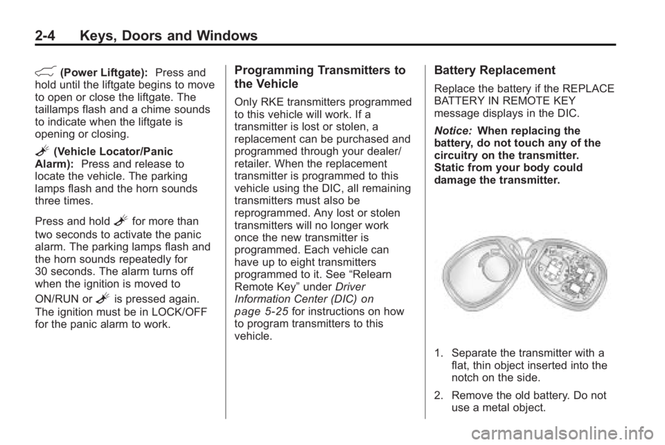
Battery Replacement
Replace the battery if the REPLACE
BATTERY IN REMOTE KEY
message displays in the DIC.
Notice: When replacing the
battery, do not touch any of the
circuitry on the transmitter.
Static from your body could
damage the transmitter.
1. Separate the transmitter with a flat, thin object inserted into the
notch on the side.
2. Remove the old battery. Do not use a metal object.
Page 41 of 438
Keys, Doors and Windows 2-13
during the ten second pre-alarm, the
alarm goes off. The headlamps flash
and the horn sounds for about
30 seconds, then turns off to save
the battery power.
The vehicle can be started with the
correct ignition key if the alarm has
been set off.
To avoid setting off the alarm by
accident:
.Lock the vehicle with the door
key after the doors are closed.
.Unlock the door with the RKE
transmitter. Unlocking a door any
other way sets off the alarm if
the system has been armed.
Press
Kor place the key in the
ignition and turn it to START to turn
off the alarm.
Testing the Alarm
To test the alarm:
1. From inside the vehicle, lower the driver side window and open
the driver door.
2. Press
Q.
3. Get out of the vehicle, close the door and wait for the security
light to go out.
4. Then reach in through the window, unlock the door with the
manual door lock and open the
door. This should set off the
alarm.
If the alarm does not sound when it
should, but the vehicle's headlamps
flash, check to see if the horn
works. The horn fuse may be blown.
To replace the fuse, see Fuses and
Circuit Breakers on page 10‑31.
If the alarm does not sound or the
vehicle's headlamps do not flash,
see your dealer/retailer for service.
Immobilizer
See Radio Frequency Statementon
page 13‑16for information
regarding Part 15 of the Federal
Communications Commission (FCC)
Rules and RSS-210/211 of Industry
and Science Canada.
Immobilizer Operation
This vehicle has PASS-Key®III+
(Personalized Automotive Security
System) theft-deterrent system.
PASS-Key
®III+ is a passive
theft-deterrent system.
The system is automatically armed
when the key is removed from the
ignition.
The system is automatically
disarmed when the key is turned to
ON/RUN, ACC/ACCESSORY or
START from the LOCK/OFF
position.
Page 189 of 438
Infotainment System 7-11
Radio Reception
Frequency interference and static
can occur during normal radio
reception if items such as cell phone
chargers, vehicle convenience
accessories, and external electronic
devices are plugged into the
accessory power outlet. If there is
interference or static, unplug the
item from the accessory power
outlet.
FM
FM signals only reach about 16 to
65 km (10 to 40 miles). Although the
radio has a built-in electronic circuit
that automatically works to reduce
interference, some static can occur,
especially around tall buildings or
hills, causing the sound to fade in
and out.
AM
The range for most AM stations is
greater than for FM, especially at
night. The longer range can cause
station frequencies to interfere with
each other. For better radioreception, most AM radio stations
boost the power levels during the
day, and then reduce these levels
during the night. Static can also
occur when things like storms and
power lines interfere with radio
reception. When this happens, try
reducing the treble on the radio.
XM™
Satellite Radio Service
XM Satellite Radio Service gives
digital radio reception from
coast-to-coast in the 48 contiguous
United States, and in Canada. Just
as with FM, tall buildings or hills can
interfere with satellite radio signals,
causing the sound to fade in and
out. In addition, traveling or standing
under heavy foliage, bridges,
garages, or tunnels may cause loss
of the XM signal for a period of time.
Cellular Phone Usage
Cellular phone usage may cause
interference with the vehicle's radio.
This interference may occur when
making or receiving phone calls,
charging the phone's battery, or simply having the phone on. This
interference can cause an increased
level of static while listening to the
radio. If static is received while
listening to the radio, unplug the
cellular phone and turn it off.
Multi-Band Antenna
The multi-band antenna is located
on the roof of the vehicle. This type
of antenna is used with the AM/FM
radio, as well as OnStar
®and the
XM™ Satellite Radio Service
System, if the vehicle has these
features. Keep this antenna clear of
snow and ice build up for clear radio
reception. If the vehicle has a
sunroof, the performance of the
radio system may be affected if the
sunroof is open. Loading items onto
the roof of the vehicle can interfere
with the performance of the radio
system and, if the vehicle has this
feature, OnStar
®. Make sure the
multi-band antenna is not
obstructed.
Page 296 of 438

9-54 Driving and Operating
Weight-Distributing Hitches and
Weight Carrying Hitches
A. Body-to-Ground Distance
B. Front of Vehicle
When using a weight-distributing
hitch, the hitch must be adjusted so
that the distance (A) remains the
same both before and after coupling
the trailer to the tow vehicle.
Safety Chains
Always attach chains between the
vehicle and the trailer. Cross the
safety chains under the tongue of
the trailer to help prevent the tongue
from contacting the road if it
becomes separated from the hitch.
Always leave just enough slack so
the rig can turn. Never allow safety
chains to drag on the ground.
Trailer Brakes
A loaded trailer that weighs more
than 450 kg (1,000 lbs) needs to
have its own brake system that is
adequate for the weight of the
trailer. Be sure to read and follow
the instructions for the trailer brakes
so they are installed, adjusted and
maintained properly.
Because the vehicle has antilock
brakes, do not try to tap into the
vehicle's hydraulic brake system.
If you do, both brake systems will
not work well, or at all.
Trailer Wiring Harness
Basic Trailer Wiring
The trailer wiring harness, with a
seven-pin connector, is located at
the rear of the vehicle and is tied to
the vehicle's frame. The harness
connector can be plugged into a
seven-pin universal heavy-duty
trailer connector available through
your dealer/retailer.
The seven-wire harness contains
the following trailer circuits:
.Yellow: Left Stop/Turn Signal
.Dark Green: Right Stop/Turn
Signal
.Brown: Taillamps
.Black: Ground
.Light Green: Back-up Lamps
.Red/Black: Battery Feed
.Dark Blue: Trailer Brake*
*The fuse for this circuit is installed
in the underhood electrical center,
but the wires are not connected.
Page 297 of 438

Driving and Operating 9-55
They should be connected by your
dealer/retailer or a qualified service
center.
If the back-up lamp circuit is not
functional, contact your dealer/
retailer.
If a remote (non-vehicle) battery is
being charged, press the Tow/Haul
mode switch located on the center
console near the climate controls.
This will boost the vehicle system
voltage and properly charge the
battery. If the trailer is too light for
Tow/Haul mode, turn on the
headlamps (Non-HID only) as a
second way to boost the vehicle
system and charge the battery.Electric Trailer Brake Control
Wiring Provisions
These wiring provisions for an
electric trailer brake controller are
included with the vehicle as part of
the trailer wiring package. The
instrument panel contains blunt cut
wires behind the steering column for
the electric trailer brake controller.
The harness contains the following
wires:
.Red/Black: Power Supply
.White: Brake Switch Signal
.Gray: Illumination
.Dark Blue: Trailer Brake Signal
.Black: Ground
The electric trailer brake controller
should be installed by your dealer/
retailer or a qualified service center.
Conversions and
Add-Ons
Add-On Electrical
Equipment
Notice: Do not add anything
electrical to the vehicle unless
you check with your dealer/
retailer first. Some electrical
equipment can damage the
vehicle and the damage would
not be covered by the vehicle's
warranty. Some add-on electrical
equipment can keep other
components from working as
they should.
Add-on equipment can drain the
vehicle battery, even if the vehicle is
not operating.
The vehicle has an airbag system.
Before attempting to add anything
electrical to the vehicle, see
Servicing the Airbag-Equipped
Vehicle
on page 3‑41and Adding
Equipment to the Airbag-Equipped
Vehicle on page 3‑42.
Page 299 of 438
Vehicle Care 10-1
Vehicle Care
General Information
General Information . . . . . . . . . . 10-2
California Proposition65 Warning . . . . . . . . . . . . . . . . . 10-3
California Perchlorate Materials Requirements . . . . 10-3
Accessories and Modifications . . . . . . . . . . . . . . . 10-3
Vehicle Checks
Doing Your OwnService Work . . . . . . . . . . . . . . . 10-4
Hood . . . . . . . . . . . . . . . . . . . . . . . . 10-4
Engine Compartment Overview . . . . . . . . . . . . . . . . . . . 10-6
Engine Cover . . . . . . . . . . . . . . . . 10-7
Engine Oil . . . . . . . . . . . . . . . . . . . 10-8
Engine Oil Life System . . . . . 10-10
Automatic Transmission Fluid . . . . . . . . . . . . . . . . . . . . . . 10-11
Engine Air Cleaner/Filter . . . . 10-12
Cooling System . . . . . . . . . . . . 10-14
Engine Coolant . . . . . . . . . . . . . 10-14
Engine Overheating . . . . . . . . 10-18 Overheated Engine
Protection
Operating Mode . . . . . . . . . . . 10-20
Power Steering Fluid . . . . . . . 10-20
Washer Fluid . . . . . . . . . . . . . . . 10-21
Brakes . . . . . . . . . . . . . . . . . . . . . 10-22
Brake Fluid . . . . . . . . . . . . . . . . . 10-23
Battery . . . . . . . . . . . . . . . . . . . . . 10-25
All-Wheel Drive . . . . . . . . . . . . . 10-25
Starter Switch Check . . . . . . . 10-25
Automatic Transmission Shift Lock Control System
Check . . . . . . . . . . . . . . . . . . . . . 10-26
Ignition Transmission Lock Check . . . . . . . . . . . . . . . . . . . . . 10-26
Park Brake and P (Park) Mechanism Check . . . . . . . . 10-26
Wiper Blade Replacement . . . . . . . . . . . . . . 10-27
Windshield Replacement . . . 10-28
Headlamp Aiming
Headlamp Aiming . . . . . . . . . . 10-28
Bulb Replacement
Bulb Replacement . . . . . . . . . . 10-28
Halogen Bulbs . . . . . . . . . . . . . . 10-28
High Intensity Discharge (HID) Lighting . . . . . . . . . . . . . 10-29 Taillamps, Turn Signal,
Sidemarker, and
Stoplamps . . . . . . . . . . . . . . . . 10-29
License Plate Lamp . . . . . . . . 10-30
Replacement Bulbs . . . . . . . . . 10-30
Electrical System
High Voltage Devices and Wiring . . . . . . . . . . . . . . . . . . . . . 10-30
Electrical System Overload . . . . . . . . . . . . . . . . . . 10-31
Fuses and Circuit Breakers . . . . . . . . . . . . . . . . . . 10-31
Engine Compartment Fuse Block . . . . . . . . . . . . . . . . . . . . . 10-31
Instrument Panel Fuse Block . . . . . . . . . . . . . . . . . . . . . 10-35
Wheels and Tires
Tires . . . . . . . . . . . . . . . . . . . . . . . . 10-37
Tire Sidewall Labeling . . . . . . 10-38
Tire Designations . . . . . . . . . . . 10-40
Tire Terminology and
Definitions . . . . . . . . . . . . . . . . 10-41
Tire Pressure . . . . . . . . . . . . . . . 10-44
Tire Pressure Monitor System . . . . . . . . . . . . . . . . . . . 10-45
Tire Pressure Monitor Operation . . . . . . . . . . . . . . . . . 10-46
Page 428 of 438
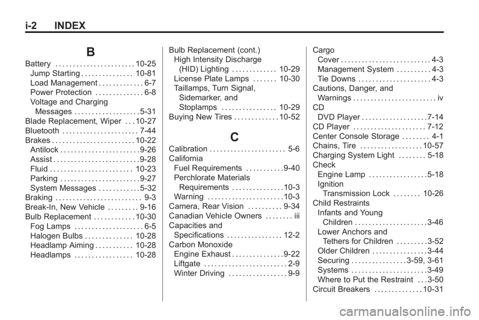
i-2 INDEX
B
Battery . . . . . . . . . . . . . . . . . . . . . . . 10-25Jump Starting . . . . . . . . . . . . . . . 10-81
Load Management . . . . . . . . . . . . . 6-7
Power Protection . . . . . . . . . . . . . . 6-8
Voltage and ChargingMessages . . . . . . . . . . . . . . . . . . . 5-31
Blade Replacement, Wiper . . . 10-27
Bluetooth . . . . . . . . . . . . . . . . . . . . . . 7-44
Brakes . . . . . . . . . . . . . . . . . . . . . . . . 10-22 Antilock . . . . . . . . . . . . . . . . . . . . . . . 9-26
Assist . . . . . . . . . . . . . . . . . . . . . . . . . 9-28
Fluid . . . . . . . . . . . . . . . . . . . . . . . . 10-23
Parking . . . . . . . . . . . . . . . . . . . . . . . 9-27
System Messages . . . . . . . . . . . . 5-32
Braking . . . . . . . . . . . . . . . . . . . . . . . . . 9-3
Break-In, New Vehicle . . . . . . . . . 9-16
Bulb Replacement . . . . . . . . . . . . 10-30
Fog Lamps . . . . . . . . . . . . . . . . . . . . 6-5
Halogen Bulbs . . . . . . . . . . . . . . 10-28
Headlamp Aiming . . . . . . . . . . . 10-28
Headlamps . . . . . . . . . . . . . . . . . 10-28 Bulb Replacement (cont.)
High Intensity Discharge
(HID) Lighting . . . . . . . . . . . . . 10-29
License Plate Lamps . . . . . . . 10-30
Taillamps, Turn Signal,
Sidemarker, and
Stoplamps . . . . . . . . . . . . . . . . 10-29
Buying New Tires . . . . . . . . . . . . . 10-52
C
Calibration . . . . . . . . . . . . . . . . . . . . . . 5-6
California Fuel Requirements . . . . . . . . . . . 9-40
Perchlorate MaterialsRequirements . . . . . . . . . . . . . . . 10-3
Warning . . . . . . . . . . . . . . . . . . . . . . 10-3
Camera, Rear Vision . . . . . . . . . . 9-34
Canadian Vehicle Owners . . . . . . . . iii
Capacities and Specifications . . . . . . . . . . . . . . . . 12-2
Carbon Monoxide Engine Exhaust . . . . . . . . . . . . . . . 9-22
Liftgate . . . . . . . . . . . . . . . . . . . . . . . . 2-9
Winter Driving . . . . . . . . . . . . . . . . . 9-9 Cargo
Cover . . . . . . . . . . . . . . . . . . . . . . . . . . 4-3
Management System . . . . . . . . . . 4-3
Tie Downs . . . . . . . . . . . . . . . . . . . . . 4-3
Cautions, Danger, and Warnings . . . . . . . . . . . . . . . . . . . . . . . . iv
CD
DVD Player . . . . . . . . . . . . . . . . . . . 7-14
CD Player . . . . . . . . . . . . . . . . . . . . . 7-12
Center Console Storage . . . . . . . . 4-1
Chains, Tire . . . . . . . . . . . . . . . . . . 10-57
Charging System Light . . . . . . . . 5-18
Check Engine Lamp . . . . . . . . . . . . . . . . . 5-18
IgnitionTransmission Lock . . . . . . . . 10-26
Child Restraints Infants and YoungChildren . . . . . . . . . . . . . . . . . . . . . 3-46
Lower Anchors and Tethers for Children . . . . . . . . . 3-52
Older Children . . . . . . . . . . . . . . . . 3-44
Securing . . . . . . . . . . . . . . . . 3-59, 3-61
Systems . . . . . . . . . . . . . . . . . . . . . . 3-49
Where to Put the Restraint . . . 3-50
Circuit Breakers . . . . . . . . . . . . . . 10-31