panel BUICK LUCERNE 2009 User Guide
[x] Cancel search | Manufacturer: BUICK, Model Year: 2009, Model line: LUCERNE, Model: BUICK LUCERNE 2009Pages: 436
Page 99 of 436
PASS-Key®III+ Electronic
Immobilizer Operation
Your vehicle is equipped with PASS-Key®III+
(Personalized Automotive Security System)
theft-deterrent system. PASS-Key
®III+ is a passive
theft-deterrent system.
The system is automatically armed when the key is
removed from the ignition.
You do not have to manually arm or disarm the system.
The security light will come on if there is a problem
with arming or disarming the theft-deterrent system.
When the PASS-Key
®III+ system senses that someone
is using the wrong key, it prevents the vehicle from
starting. Anyone using a trial-and-error method to start
the vehicle will be discouraged because of the high
number of electrical key codes.
When trying to start the vehicle if the engine does not
start and the security light on the instrument panel
cluster comes on, there may be a problem with your
theft-deterrent system. Turn the ignition off and try again.If the engine still does not start, and the key appears to
be not damaged, try another ignition key. At this time, you
may also want to check the fuse, seeFuses and Circuit
Breakers on page 5-101. If the engine still does not start
with the other key, your vehicle needs service. If your
vehicle does start, the �rst key may be faulty. See your
dealer/retailer who can service the PASS-Key
®III+ to
have a new key made. In an emergency, contact
Roadside Assistance. SeeRoadside Assistance
Program on page 7-7.
It is possible for the PASS-Key
®III+ decoder to “learn”
the transponder value of a new or replacement key.
Up to 10 keys may be programmed for the vehicle.
The following procedure is for programming additional
keys only. If all the currently programmed keys are lost
or do not operate, you must see your dealer/retailer or a
locksmith who can service PASS-Key
®III+ to have keys
made and programmed to the system.
See your dealer/retailer or a locksmith who can service
PASS-Key
®III+ to get a new key blank that is cut
exactly as the ignition key that operates the system.
2-19
Page 102 of 436
Retained Accessory Power (RAP)
The following accessories can be used for up to
10 minutes after the engine is turned off.
Audio System
Audio Steering Wheel (if equipped)
Clock
Power Windows
Sunroof (if equipped)
Power to these accessories works up to 10 minutes or
until the driver door is opened.The instrument panel cluster lights stay on for a
few seconds, then will go out. Once the driver door
is opened, the power shuts off to these accessories.
The vehicle has a feature designed to protect the battery
against drainage. For more information seeInadvertent
Power Battery Saver on page 3-19andElectric
Power Management on page 3-19.
Starting the Engine
Move the shift lever to P (Park) or N (Neutral). The
engine will not start in any other position. To restart
the engine when the vehicle is already moving, use
N (Neutral) only.
Notice:Do not try to shift to P (Park) if the vehicle
is moving. If you do, you could damage the
transmission. Shift to P (Park) only when the
vehicle is stopped.
2-22
Page 107 of 436

2 (Second):This position reduces vehicle speed even
more than 3 (Third) without using the brakes. You
can use 2 (Second) on hills. It can help control vehicle
speed as you go down steep mountain roads, but
then you would also want to use the brakes off and on.
Notice:Driving in 2 (Second) for more than
25 miles (40 km) or at speeds over 55 mph (90 km/h)
may damage the transmission. Also, shifting into
2 (Second) at speeds above 65 mph (105 km/h) can
cause damage. Drive in 3 (Third) or D (Drive)
instead of 2 (Second).
1 (First):This position reduces vehicle speed even
more than 2 (Second) without using the brakes. You can
use it on very steep hills, or in deep snow or mud. If the
shift lever is put in 1 (First) while going forward, the
transmission will not shift into �rst gear until the vehicle
is going slowly enough.
Notice:Spinning the tires or holding the vehicle in
one place on a hill using only the accelerator pedal
may damage the transmission. The repair will not be
covered by the vehicle warranty. If you are stuck, do
not spin the tires. When stopping on a hill, use the
brakes to hold the vehicle in place.Parking Brake
The parking brake pedal is
located to the left of the
regular brake pedal,
near the driver door.
To set the parking brake, hold the regular brake pedal
down, then push the parking brake pedal down.
If the ignition is on, the brake system warning light on
the instrument panel cluster should come on. If it
does not, you need to have the vehicle serviced.
2-27
Page 125 of 436
How the System Works
LDW uses a camera located between the inside
rearview mirror and the windshield to detect the lane
markings.
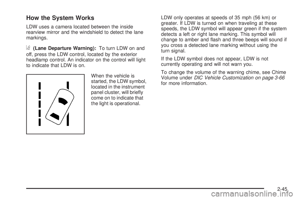
@(Lane Departure Warning):To turn LDW on and
off, press the LDW control, located by the exterior
headlamp control. An indicator on the control will light
to indicate that LDW is on.
When the vehicle is
started, the LDW symbol,
located in the instrument
panel cluster, will brie�y
come on to indicate that
the light is operational.LDW only operates at speeds of 35 mph (56 km) or
greater. If LDW is turned on when traveling at these
speeds, the LDW symbol will appear green if the system
detects a left or right lane marking. This symbol will
change to amber and �ash and three beeps will sound if
you cross a detected lane marking without using the
turn signal.
If the LDW symbol does not appear, LDW is not
currently operating and will not warn you.
To change the volume of the warning chime, see Chime
Volume underDIC Vehicle Customization on page 3-66
for more information.
2-45
Page 134 of 436

The garage door opener receiver (motor head unit)
could also have a row of dip switches that can be
used when programming the Universal Home
Remote. If the total number of switches on the motor
head and hand held transmitter are different, or if the
dip switch settings are different, use the dip switch
settings on the motor head unit to program the
Universal Home Remote. The motor head dip switch
settings can also be used when the original hand
held transmitter is not available.
The panel of switches might not appear exactly as
they do in the examples above, but they should
be similar.
The switch positions on the hand-held transmitter
could be labeled, as follows:
A switch in the up position could be labeled as
“Up,” “+,” or “On.”
A switch in the down position could be labeled
as “Down,” “−,” or “Off.”
A switch in the middle position could be labeled
as “Middle,” “0,” or “Neutral.” Example of Eight Dip Switches with Two Positions
Example of Eight Dip Switches with Three Positions
2-54
Page 139 of 436
Instrument Panel Overview...............................3-4
Hazard Warning Flashers................................3-6
Horn .............................................................3-6
Tilt Wheel.....................................................3-6
Power Tilt Wheel and Telescopic Steering
Column......................................................3-7
Heated Steering Wheel...................................3-7
Turn Signal/Multifunction Lever.........................3-8
Turn and Lane-Change Signals........................3-8
Headlamp High/Low-Beam Changer..................3-9
Flash-to-Pass.................................................3-9
Windshield Wipers..........................................3-9
Rainsense™ II Wipers...................................3-10
Windshield Washer.......................................3-11
Cruise Control..............................................3-12
Exterior Lamps.............................................3-15
Wiper Activated Headlamps............................3-16
Headlamps on Reminder................................3-16
Daytime Running Lamps (DRL).......................3-16
Fog Lamps ..................................................3-17
Cornering Lamps..........................................3-17
Exterior Lighting Battery Saver........................3-17
Instrument Panel Brightness...........................3-17
Courtesy Lamps...........................................3-18
Entry Lighting...............................................3-18
Delayed Entry Lighting...................................3-18
Theater Dimming..........................................3-18Delayed Exit Lighting.....................................3-18
Perimeter Lighting.........................................3-18
Front Reading Lamps....................................3-18
Electric Power Management...........................3-19
Inadvertent Power Battery Saver.....................3-19
Battery Run-Down Protection..........................3-20
Accessory Power Outlet(s).............................3-20
Ashtray(s)....................................................3-21
Climate Controls............................................3-21
Climate Control System.................................3-21
Dual Automatic Climate Control System...........3-24
Outlet Adjustment.........................................3-30
Passenger Compartment Air Filter...................3-30
Warning Lights, Gages, and Indicators............3-32
Instrument Panel Cluster................................3-33
Speedometer and Odometer...........................3-34
Trip Odometer..............................................3-34
Tachometer.................................................3-34
Safety Belt Reminders...................................3-35
Airbag Readiness Light..................................3-36
Passenger Airbag Status Indicator...................3-37
Charging System Light..................................3-38
Brake System Warning Light..........................3-38
Antilock Brake System (ABS) Warning Light.....3-39
Traction Control System (TCS) Warning Light . . .3-40
StabiliTrak
®Indicator Light.............................3-41
Section 3 Instrument Panel
3-1
Page 140 of 436
Lane Departure Warning Light........................3-41
Engine Coolant Temperature Warning Light......3-42
Engine Coolant Temperature Gage..................3-42
Tire Pressure Light.......................................3-43
Malfunction Indicator Lamp.............................3-43
Oil Pressure Light.........................................3-46
Security Light...............................................3-46
Fog Lamp Light............................................3-47
Cruise Control Light......................................3-47
Highbeam On Light.......................................3-47
Fuel Gage...................................................3-48
Driver Information Center (DIC).......................3-49
DIC Operation and Displays...........................3-49
DIC Compass..............................................3-54DIC Warnings and Messages.........................3-56
DIC Vehicle Customization.............................3-66
Audio System(s).............................................3-75
Setting the Clock..........................................3-76
Radio(s)......................................................3-78
Using an MP3..............................................3-88
XM Radio Messages.....................................3-92
Navigation/Radio System...............................3-93
Bluetooth
®...................................................3-93
Theft-Deterrent Feature................................3-104
Audio Steering Wheel Controls......................3-104
Radio Reception.........................................3-105
Backglass Antenna......................................3-106
XM™ Satellite Radio Antenna System............3-106
Section 3 Instrument Panel
3-2
Page 142 of 436

Instrument Panel Overview
3-4
Page 143 of 436
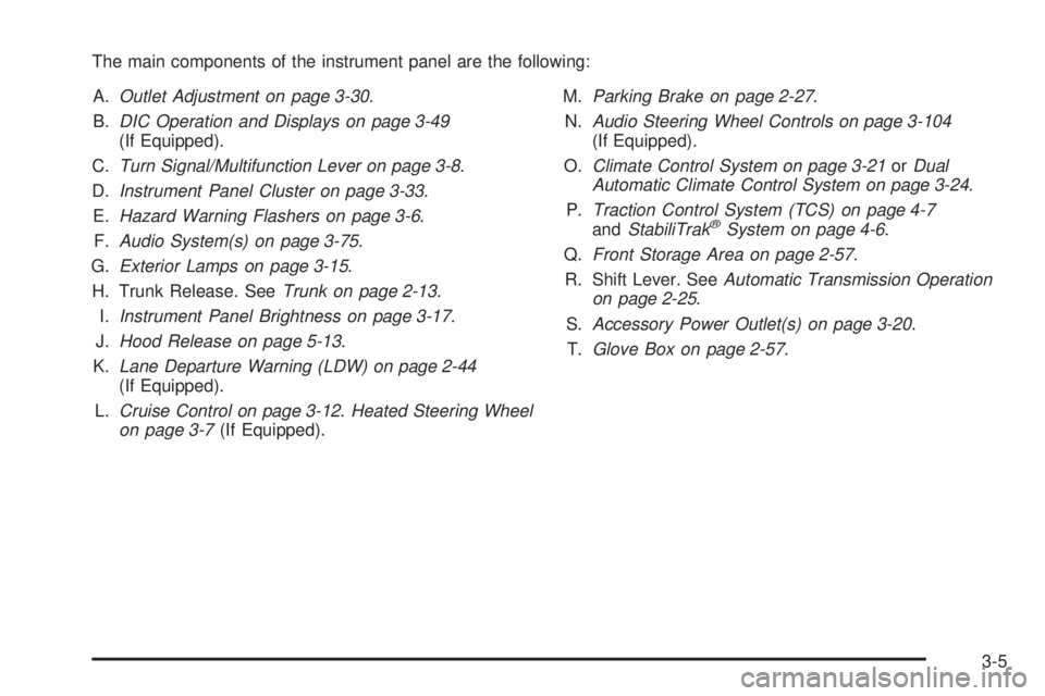
The main components of the instrument panel are the following:
A.Outlet Adjustment on page 3-30.
B.DIC Operation and Displays on page 3-49
(If Equipped).
C.Turn Signal/Multifunction Lever on page 3-8.
D.Instrument Panel Cluster on page 3-33.
E.Hazard Warning Flashers on page 3-6.
F.Audio System(s) on page 3-75.
G.Exterior Lamps on page 3-15.
H. Trunk Release. SeeTrunk on page 2-13.
I.Instrument Panel Brightness on page 3-17.
J.Hood Release on page 5-13.
K.Lane Departure Warning (LDW) on page 2-44
(If Equipped).
L.Cruise Control on page 3-12.Heated Steering Wheel
on page 3-7(If Equipped).M.Parking Brake on page 2-27.
N.Audio Steering Wheel Controls on page 3-104
(If Equipped).
O.Climate Control System on page 3-21orDual
Automatic Climate Control System on page 3-24.
P.Traction Control System (TCS) on page 4-7
andStabiliTrak
®System on page 4-6.
Q.Front Storage Area on page 2-57.
R. Shift Lever. SeeAutomatic Transmission Operation
on page 2-25.
S.Accessory Power Outlet(s) on page 3-20.
T.Glove Box on page 2-57.
3-5
Page 144 of 436

Hazard Warning Flashers
The hazard warning �ashers let you warn others that
you have a problem.
The hazard warning �asher button is located in the
center of the instrument panel above the radio.
|:Press to make the front and rear turn signal lamps
�ash on and off. Press the button again to turn the
�ashers off.
When the hazard warning �ashers are on, the turn
signals will not work.
Horn
Press near or on the horn symbols on the steering
wheel pad to sound the horn.
Tilt Wheel
A tilt wheel allows the steering wheel to be adjusted.
The tilt lever is located on
the left side of the steering
column.
To tilt the wheel, hold the wheel and pull the lever
toward you. Then move the wheel to a comfortable
position and release the lever to lock the wheel in place.
Do not adjust the steering wheel while driving.
3-6