clock BUICK LUCERNE 2010 Owner's Guide
[x] Cancel search | Manufacturer: BUICK, Model Year: 2010, Model line: LUCERNE, Model: BUICK LUCERNE 2010Pages: 474
Page 356 of 474
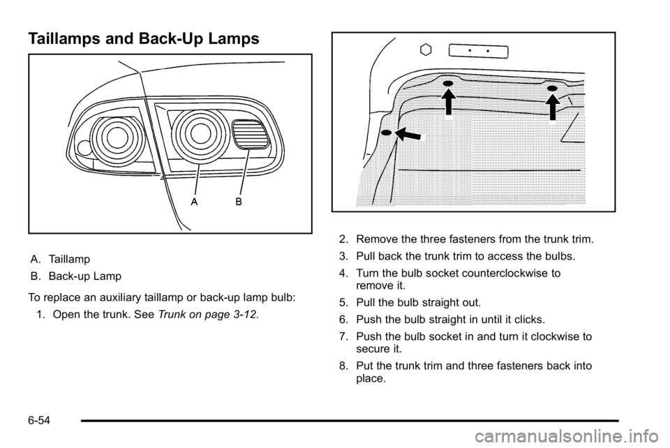
Taillamps and Back-Up Lamps
A. Taillamp
B. Back-up Lamp
To replace an auxiliary taillamp or back-up lamp bulb: 1. Open the trunk. See Trunk on page 3‑12.
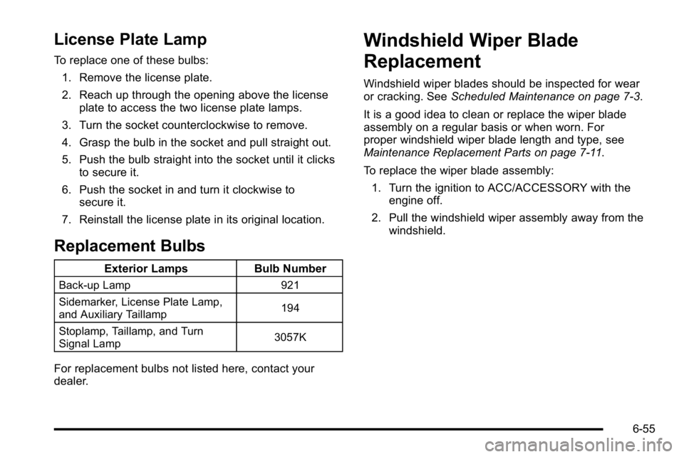
2. Remove the three fasteners from the trunk trim.
3. Pull back the trunk trim to access the bulbs.
4. Turn the bulb socket counterclockwise to
remove it.
5. Pull the bulb straight out.
6. Push the bulb straight in until it clicks.
7. Push the bulb socket in and turn it clockwise to secure it.
8. Put the trunk trim and three fasteners back into place.
6-54
Page 357 of 474
License Plate Lamp
To replace one of these bulbs:1. Remove the license plate.
2. Reach up through the opening above the license plate to access the two license plate lamps.
3. Turn the socket counterclockwise to remove.
4. Grasp the bulb in the socket and pull straight out.
5. Push the bulb straight into the socket until it clicks to secure it.
6. Push the socket in and turn it clockwise to secure it.
7. Reinstall the license plate in its original location.
Replacement Bulbs
Exterior Lamps Bulb Number
Back-up Lamp 921
Sidemarker, License Plate Lamp,
and Auxiliary Taillamp 194
Stoplamp, Taillamp, and Turn
Signal Lamp 3057K
For replacement bulbs not listed here, contact your
dealer.
Windshield Wiper Blade
Replacement
Windshield wiper blades should be inspected for wear
or cracking. See
Scheduled Maintenance on page 7‑3.
It is a good idea to clean or replace the wiper blade
assembly on a regular basis or when worn. For
proper windshield wiper blade length and type, see
Maintenance Replacement Parts on page 7‑11.
To replace the wiper blade assembly: 1. Turn the ignition to ACC/ACCESSORY with the engine off.
2. Pull the windshield wiper assembly away from the windshield.
6-55
Page 387 of 474

Always do a safety check first. SeeIf a Tire Goes Flaton page 6‑81. Do not remove any objects that have
penetrated the tire.
1. Remove the tire sealant and compressor kit from its storage location. See Tire Sealant and
Compressor Kit Storage on page 6‑90.
2. Unwrap the sealant/air hose (F) and the power plug (G).
3. Place the kit on the ground.
Make sure the tire valve stem is positioned close to
the ground so the hose will reach it.
4. Remove the valve stem cap from the flat tire by turning it counterclockwise.
5. Attach the sealant/air hose (F) onto the tire valve stem. Turn it clockwise until it is tight.
6. Plug the power plug (G) into the accessory power outlet in the vehicle. Unplug all items from other
accessory power outlets. See Accessory Power
Outlet(s) on page 4‑17. If the vehicle has an accessory power outlet, do
not use the cigarette lighter.
If the vehicle only has a cigarette lighter, use the
cigarette lighter.
Do not pinch the power plug cord in the door or
window.
7. Start the vehicle. The vehicle must be running while using the air compressor.
8. Turn the selector switch (B) clockwise to the Sealant + Air position.
9. Press the on/off (A) button to turn the tire sealant and compressor kit on.
The compressor will inject sealant and air into
the tire.
The pressure gauge (D) will initially show a high
pressure while the compressor pushes the sealant
into the tire. Once the sealant is completely
dispersed into the tire, the pressure will quickly
drop and start to rise again as the tire inflates with
air only.
6-85
Page 388 of 474
10. Inflate the tire to the recommended inflationpressure using the pressure gauge (D). The
recommended inflation pressure can be found on
the Tire and Loading Information label. See
Inflation - Tire Pressure on page 6‑65.
The pressure gauge (D) may read higher than the
actual tire pressure while the compressor is on.
Turn the compressor off to get an accurate
pressure reading. The compressor may be turned
on/off until the correct pressure is reached.
Notice: If the recommended pressure cannot be
reached after approximately 25 minutes, the vehicle
should not be driven farther. The tire is too severely
damaged and the tire sealant and compressor kit
cannot inflate the tire. Remove the power plug from
the accessory power outlet and unscrew the
inflating hose from the tire valve. See Roadside
Assistance Program on page 8‑8.
11. Press the on/off button (A) to turn the tire sealant and compressor kit off.
The tire is not sealed and will continue to leak
air until the vehicle is driven and the sealant is
distributed in the tire, therefore, Steps 12
through 18 must be done immediately after
Step 11.
Be careful while handling the tire sealant and
compressor kit as it could be warm after usage. 12. Unplug the power plug (G) from the accessory
power outlet in the vehicle.
13. Turn the sealant/air hose (F) counterclockwise to remove it from the tire valve stem.
14. Replace the tire valve stem cap.
15. Replace the sealant/air hose (F), and the power plug (G) back in their original location.
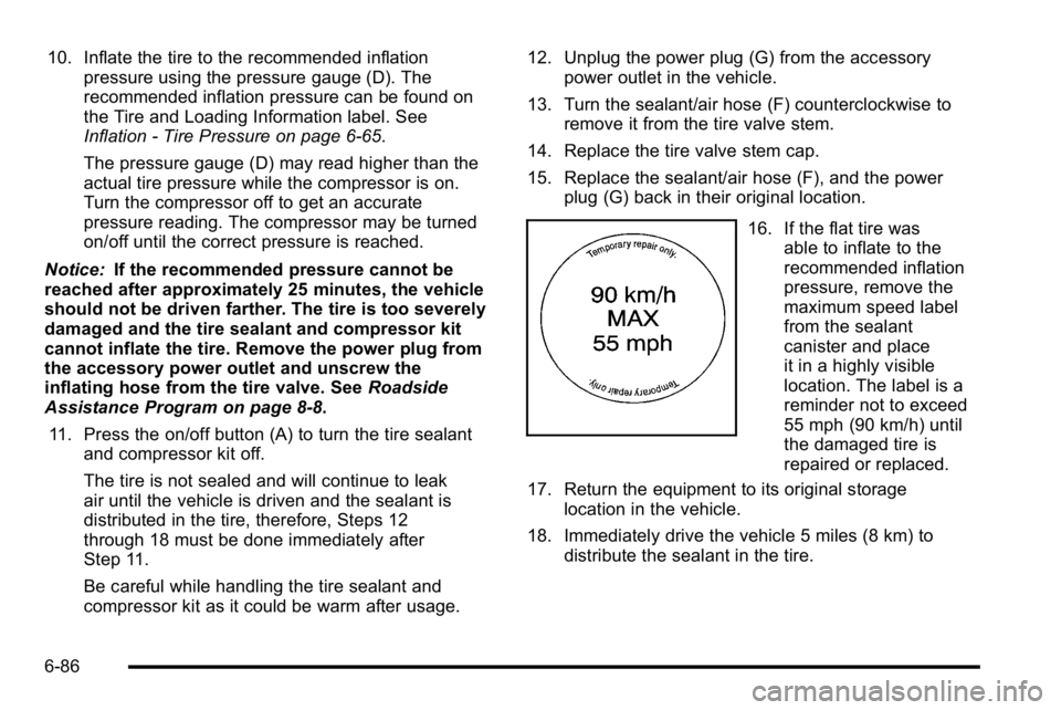
16. If the flat tire wasable to inflate to the
recommended inflation
pressure, remove the
maximum speed label
from the sealant
canister and place
it in a highly visible
location. The label is a
reminder not to exceed
55 mph (90 km/h) until
the damaged tire is
repaired or replaced.
17. Return the equipment to its original storage location in the vehicle.
18. Immediately drive the vehicle 5 miles (8 km) to distribute the sealant in the tire.
6-86
Page 390 of 474

3. Place the kit on the ground.Make sure the tire valve stem is positioned close to
the ground so the hose will reach it.
4. Remove the tire valve stem cap from the flat tire by turning it counterclockwise.
5. Attach the air only hose (E) onto the tire valve stem by turning it clockwise until it is tight.
6. Plug the power plug (G) into the accessory power outlet in the vehicle. Unplug all items from other
accessory power outlets. See Accessory Power
Outlet(s) on page 4‑17.
If the vehicle has an accessory power outlet, do
not use the cigarette lighter.
If the vehicle only has a cigarette lighter, use the
cigarette lighter.
Do not pinch the power plug cord in the door or
window.
7. Start the vehicle. The vehicle must be running while using the air compressor.
8. Turn the selector switch (B) counterclockwise to the Air Only position.
9. Press the on/off (A) button to turn the compressor on.
The compressor will inflate the tire with air only. 10. Inflate the tire to the recommended inflation
pressure using the pressure gauge (D). The
recommended inflation pressure can be found on
the Tire and Loading Information label. See
Inflation - Tire Pressure on page 6‑65.
The pressure gauge (D) may read higher than the
actual tire pressure while the compressor is on.
Turn the compressor off to get an accurate
reading. The compressor may be turned on/off until
the correct pressure is reached.
11. Press the on/off button (A) to turn the tire sealant and compressor kit off.
Be careful while handling the tire sealant and
compressor kit as it could be warm after usage.
12. Unplug the power plug (G) from the accessory power outlet in the vehicle.
13. Disconnect the air only hose (E) from the tire valve stem, by turning it counterclockwise, and replace
the tire valve stem cap.
14. Replace the air only hose (E) and the power plug (G) and cord back in its original location.
15. Place the equipment in the original storage location in the vehicle.
6-88
Page 392 of 474

Tire Sealant and Compressor Kit
Storage
The tire sealant and compressor kit is located in the
trunk.1. Open the trunk. See Trunk on page 3‑12
2. Lift the cover.
3. Turn the retainer clockwise and remove the tire sealant and compressor kit.
To store the tire sealant and compressor kit, reverse the
steps.
Changing a Flat Tire
If a tire goes flat, avoid further tire and wheel damage
by driving slowly to a level place. Turn on the hazard
warning flashers. See Hazard Warning Flashers
on
page 4‑3.
{WARNING:
Changing a tire can be dangerous. The vehicle
can slip off the jack and roll over or fall on you or
other people. You and they could be badly injured
or even killed. Find a level place to change your
tire. To help prevent the vehicle from moving:
1. Set the parking brake firmly.
2. Put the shift lever in P (Park). (Continued)
6-90
Page 394 of 474
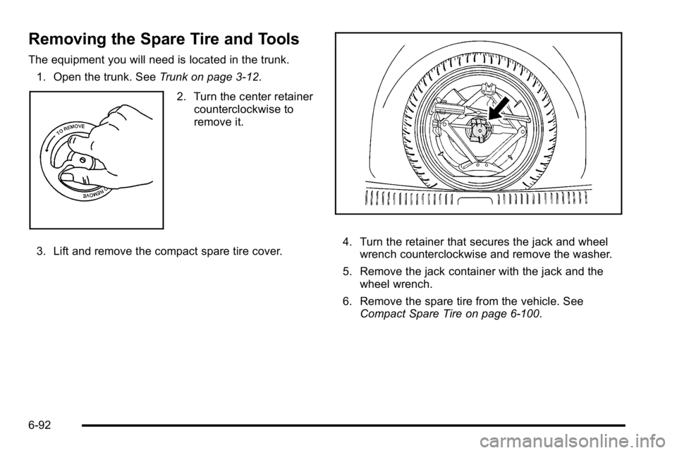
Removing the Spare Tire and Tools
The equipment you will need is located in the trunk.1. Open the trunk. See Trunk on page 3‑12.
2. Turn the center retainer
counterclockwise to
remove it.
3. Lift and remove the compact spare tire cover.
4. Turn the retainer that secures the jack and wheel wrench counterclockwise and remove the washer.
5. Remove the jack container with the jack and the wheel wrench.
6. Remove the spare tire from the vehicle. See Compact Spare Tire on page 6‑100.
6-92
Page 395 of 474
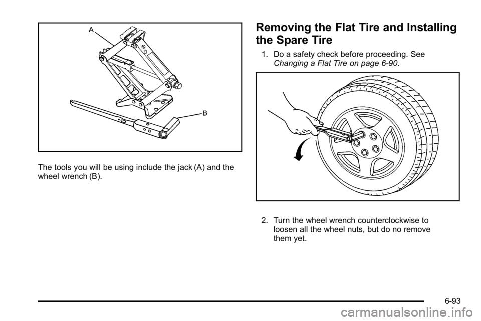
The tools you will be using include the jack (A) and the
wheel wrench (B).
Removing the Flat Tire and Installing
the Spare Tire
1. Do a safety check before proceeding. SeeChanging a Flat Tire on page 6‑90.
2. Turn the wheel wrench counterclockwise toloosen all the wheel nuts, but do no remove
them yet.
6-93
Page 396 of 474
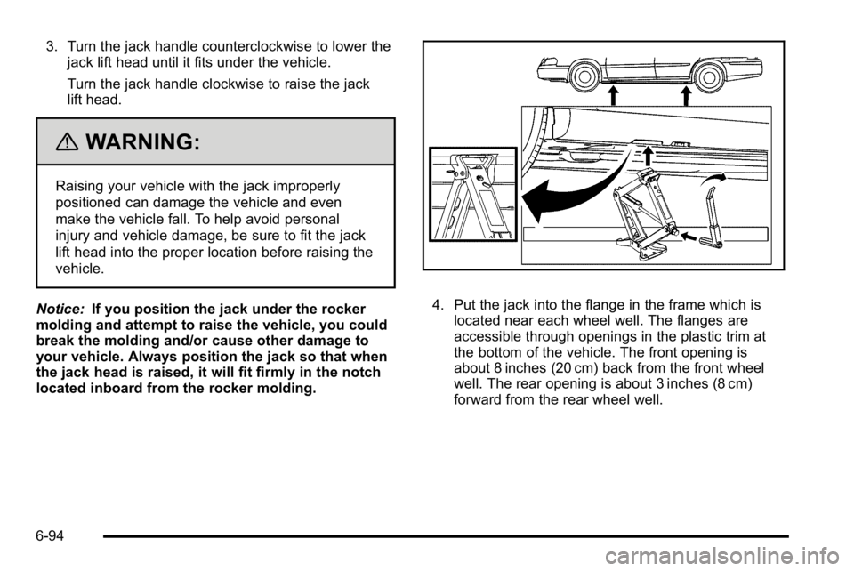
3. Turn the jack handle counterclockwise to lower thejack lift head until it fits under the vehicle.
Turn the jack handle clockwise to raise the jack
lift head.
{WARNING:
Raising your vehicle with the jack improperly
positioned can damage the vehicle and even
make the vehicle fall. To help avoid personal
injury and vehicle damage, be sure to fit the jack
lift head into the proper location before raising the
vehicle.
Notice: If you position the jack under the rocker
molding and attempt to raise the vehicle, you could
break the molding and/or cause other damage to
your vehicle. Always position the jack so that when
the jack head is raised, it will fit firmly in the notch
located inboard from the rocker molding.
4. Put the jack into the flange in the frame which is located near each wheel well. The flanges are
accessible through openings in the plastic trim at
the bottom of the vehicle. The front opening is
about 8 inches (20 cm) back from the front wheel
well. The rear opening is about 3 inches (8 cm)
forward from the rear wheel well.
6-94
Page 397 of 474
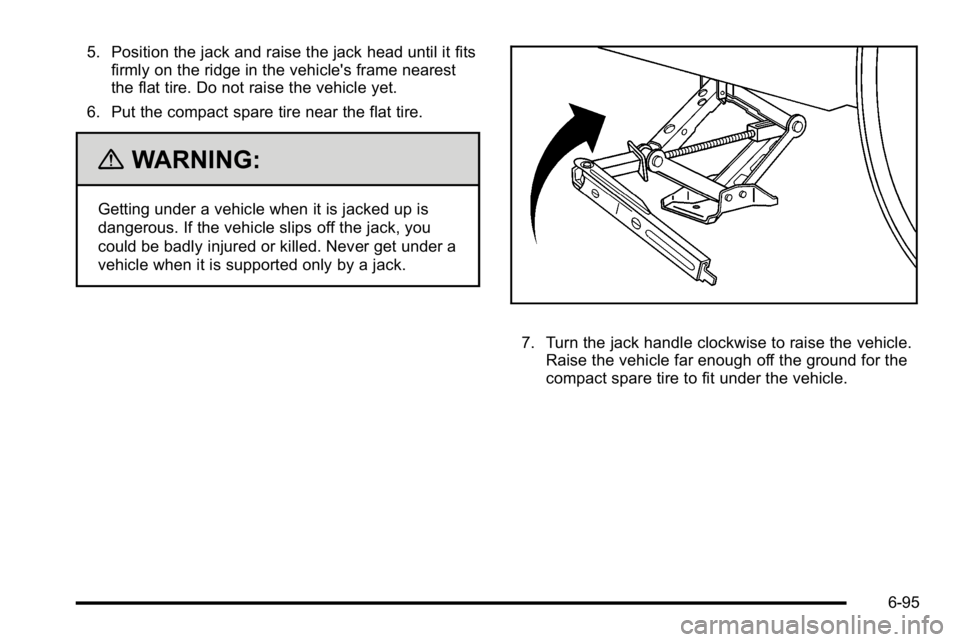
5. Position the jack and raise the jack head until it fitsfirmly on the ridge in the vehicle's frame nearest
the flat tire. Do not raise the vehicle yet.
6. Put the compact spare tire near the flat tire.
{WARNING:
Getting under a vehicle when it is jacked up is
dangerous. If the vehicle slips off the jack, you
could be badly injured or killed. Never get under a
vehicle when it is supported only by a jack.
7. Turn the jack handle clockwise to raise the vehicle. Raise the vehicle far enough off the ground for the
compact spare tire to fit under the vehicle.
6-95