ECU BUICK RANDEZVOUS 2007 Repair Manual
[x] Cancel search | Manufacturer: BUICK, Model Year: 2007, Model line: RANDEZVOUS, Model: BUICK RANDEZVOUS 2007Pages: 528, PDF Size: 2.99 MB
Page 445 of 528
For vehicles with aluminum wheels, remove
the center cap by tapping the back of the cap
with the folding wrench.
3. Remove the J-hook and the wing nut from the
back of the jack access door. Assemble the
wing nut and the J-hook.
4. Install the wing nut and the J-hook to the
D-ring through the center hole of the tire.
5. Tighten the wing nut to secure the tire to
the �oor.
Push and pull on the tire to make sure the tire
is secure and does not move.
6. Put back all tools as they were stored in the
jack storage compartment and put the
compartment cover back on.
Slip the tabs on the side of the compartment
cover into the cover opening. Push the cover in
place and push down the tabs on the cover
so that it rests in the groove. This secures the
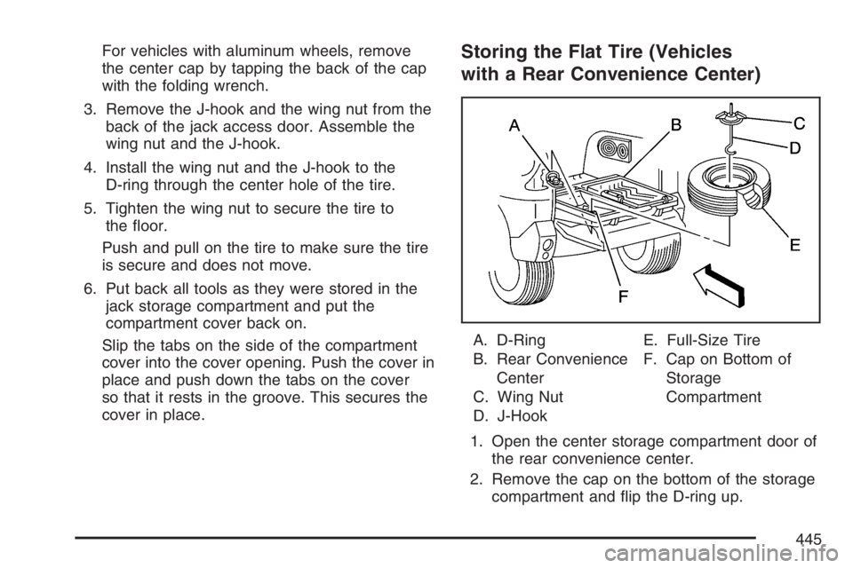
cover in place.Storing the Flat Tire (Vehicles
with a Rear Convenience Center)
A. D-Ring
B. Rear Convenience
Center
C. Wing Nut
D. J-HookE. Full-Size Tire
F. Cap on Bottom of
Storage
Compartment
1. Open the center storage compartment door of
the rear convenience center.
2. Remove the cap on the bottom of the storage
compartment and �ip the D-ring up.
445
Page 446 of 528
3. Lay the tire on top of the center storage
compartment with the valve stem down.
Make sure you can see the D-ring through
the center hole of the tire.
4. Remove the J-hook and the wing nut from the
back of the jack access door. Assemble the
wing nut and the J-hook.
5. Install the wing nut and the J-hook to the
D-ring through the center hole of the tire.
6. Tighten the wing nut to secure the tire to
the �oor.
Push and pull on the tire to make sure the tire
is secure and does not move.
7. Put back all tools as they were stored in the
jack storage compartment and put the
compartment cover back on.
Slip the tabs on the side of the compartment
cover into the cover opening. Push the cover in
place and push down the tabs on the cover
so that it rests in the groove. This secures the
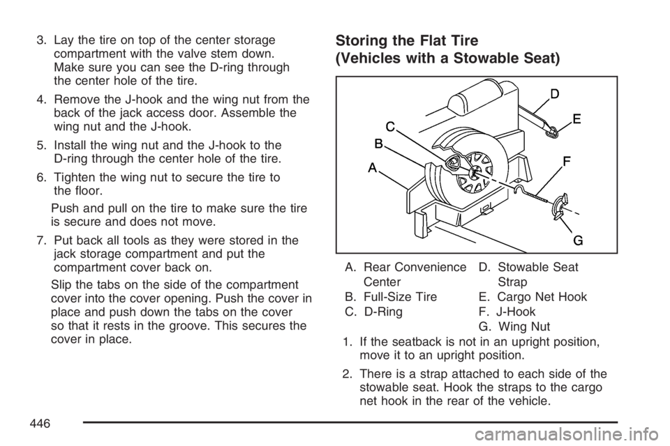
cover in place.Storing the Flat Tire
(Vehicles with a Stowable Seat)
A. Rear Convenience
Center
B. Full-Size Tire
C. D-RingD. Stowable Seat
Strap
E. Cargo Net Hook
F. J-Hook
G. Wing Nut
1. If the seatback is not in an upright position,
move it to an upright position.
2. There is a strap attached to each side of the
stowable seat. Hook the straps to the cargo
net hook in the rear of the vehicle.
446
Page 447 of 528
3. Flip the D-ring so it is pointing outward.
4. Open the convenience center cover.
5. Stand the full-size tire up, in the tray against
the back of the seat with the valve stem
pointing out.
6. Remove the J-hook and the wing nut from the
back of the jack access door. Assemble the
wing nut and the J-hook.
7. Install the wing nut and the J-hook to the
D-ring through the center hole of the tire.
8. Tighten the wing nut to secure the tire to the
seatback.
Push and pull on the tire to make sure the tire
is secure and does not move.
9. Put back all tools as they were stored in the
jack storage compartment and put the
compartment cover back on.
Slip the tabs on the side of the compartment
cover into the cover opening. Push the cover in
place and push down the tabs on the cover
so that it rests in the groove. This secures the
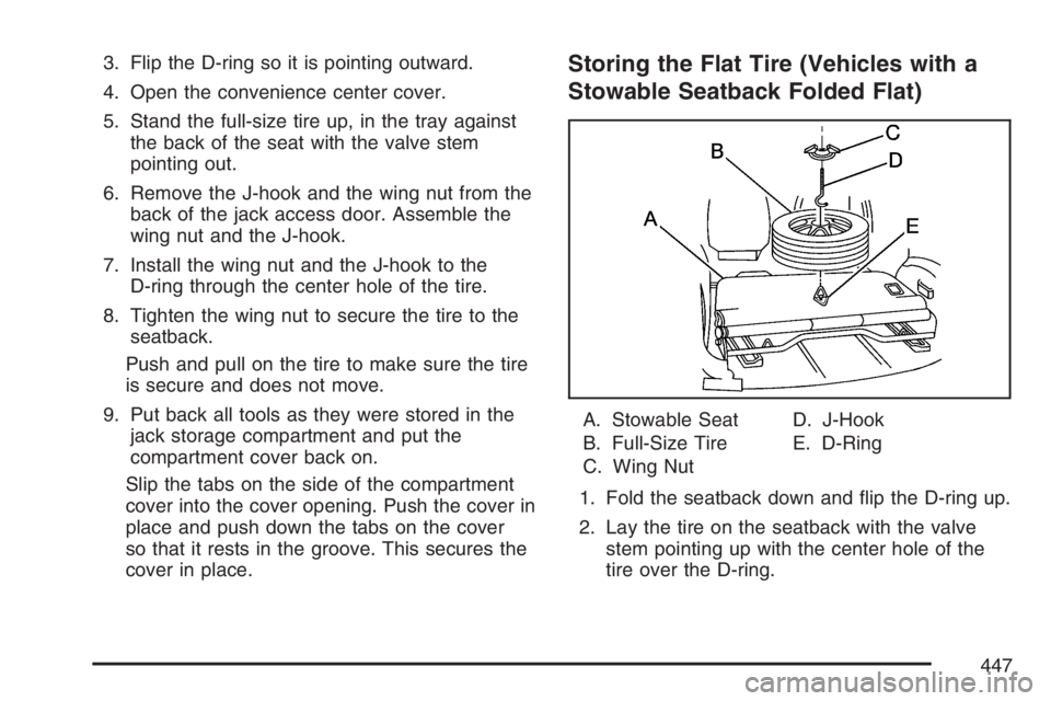
cover in place.Storing the Flat Tire (Vehicles with a
Stowable Seatback Folded Flat)
A. Stowable Seat
B. Full-Size Tire
C. Wing NutD. J-Hook
E. D-Ring
1. Fold the seatback down and �ip the D-ring up.
2. Lay the tire on the seatback with the valve
stem pointing up with the center hole of the
tire over the D-ring.
447
Page 448 of 528
3. Remove the J-hook and the wing nut from the
back of the jack access door. Assemble the
wing nut and the J-hook.
4. Install the wing nut and the J-hook to the
D-ring through the center hole of the tire.
5. Tighten the wing nut to secure the tire to the
seatback.
6. Push and pull on the tire to make sure the tire
is secure and does not move.
7. Put back all tools as they were stored in the
jack storage compartment and put the
compartment cover back on.
Slip the tabs on the side of the compartment
cover into the cover opening. Push the cover in
place and push down the tabs on the cover
so that it rests in the groove. This secures the
cover in place.Storing the Spare Tire and Tools
{CAUTION:
Storing a jack, a tire, or other equipment
in the passenger compartment of the
vehicle could cause injury. In a sudden
stop or collision, loose equipment could
strike someone. Store all these in the
proper place.
448
Page 449 of 528

{CAUTION:
The underbody-mounted spare tire needs
to be stored with the valve stem pointing
down. If the spare tire is stored with
the valve stem pointing upwards, its
secondary latch will not work properly and
the spare tire could loosen and suddenly
fall from your vehicle. If this happened
when your vehicle was being driven, the
tire might contact a person or another
vehicle, causing injury and, of course,
damage to itself as well. Be sure the
underbody-mounted spare tire is stored
with its valve stem pointing down.
1. Lay the compact spare tire on the ground at
the rear of the vehicle. Position the compact
spare tire so that the valve stem is pointed
down facing the rear of the vehicle.
2. Lower the cable to the ground. SeeRemoving
the Spare Tire and Tools on page 429.3. Tilt the retainer downward and slip it through
the center hole of the spare tire.
Make sure the retainer is fully seated across
the underside of the wheel.
4. Attach the folding wrench to the hoist shaft.
5. Turn the folding wrench clockwise to lift
the spare tire.
6. When the tire reaches the stabilizer bar, move
the tire over the bar, then continue to turn the
folding wrench clockwise to lift the spare tire.
7. When the tire is almost in the stored position,
turn the tire so that the valve stem is towards
the rear of the vehicle.
This will help when you check and maintain
tire pressure in the spare.
8. Raise the tire fully against the underside of the
vehicle. Continue turning the folding wrench
until you feel more than two clicks. This
indicates that the compact spare tire is secure
and the cable is tight. The spare tire hoist
cannot be overtightened.
449
Page 450 of 528
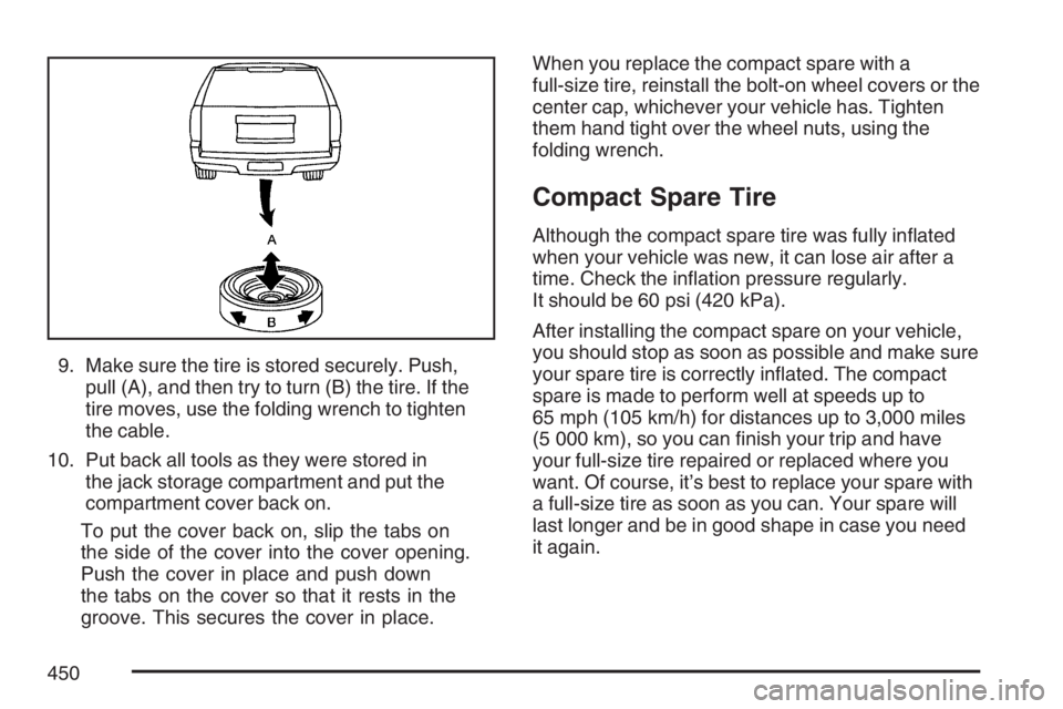
9. Make sure the tire is stored securely. Push,
pull (A), and then try to turn (B) the tire. If the
tire moves, use the folding wrench to tighten
the cable.
10. Put back all tools as they were stored in
the jack storage compartment and put the
compartment cover back on.
To put the cover back on, slip the tabs on
the side of the cover into the cover opening.
Push the cover in place and push down
the tabs on the cover so that it rests in the
groove. This secures the cover in place.When you replace the compact spare with a
full-size tire, reinstall the bolt-on wheel covers or the
center cap, whichever your vehicle has. Tighten
them hand tight over the wheel nuts, using the
folding wrench.
Compact Spare Tire
Although the compact spare tire was fully in�ated
when your vehicle was new, it can lose air after a
time. Check the in�ation pressure regularly.
It should be 60 psi (420 kPa).
After installing the compact spare on your vehicle,
you should stop as soon as possible and make sure
your spare tire is correctly in�ated. The compact
spare is made to perform well at speeds up to
65 mph (105 km/h) for distances up to 3,000 miles
(5 000 km), so you can �nish your trip and have
your full-size tire repaired or replaced where you
want. Of course, it’s best to replace your spare with
a full-size tire as soon as you can. Your spare will
last longer and be in good shape in case you need
it again.
450
Page 465 of 528
Fuse Usage
26HVAC Mode and Temperature
Motors and Head-Up Display
28 Accessory Power
29 Windshield Wipers and Washer
30Instrument Panel Cluster,
Body Control Module (BCM),
PASS-Key
®III
31 Park Lock Ignition Key Solenoid
32 Rear Window Wiper/Washer
34 Power Sunroof
35 Power Windows
36Map Lamps, Courtesy Lamps and
Instrument Panel Lights
37 Radio
38 UQ3 Radio Ampli�er
39 Head-Up Display
40 Hazard Flashers
Fuse Usage
41Instrument Panel Cluster, Climate
Control, Security LED and Remote
Keyless Entry Mode
42 PASS-Key
®III
44 Body Control Module (BCM)
46Automatic Occupant Sensing
Module
Relay Usage
20 Rear Defogger Relay
23 Ignition Relay
27 Accessory Relay
33 Retained Accessory Power Relay
43 Accessory Diode
45 Back-Up Lamps
465
Page 481 of 528

At Each Fuel Fill
It is important to perform these underhood checks
at each fuel �ll.
Engine Oil Level Check
Check the engine oil level and add the proper oil if
necessary. SeeEngine Oil on page 365for
further details.
Notice:It is important to check your oil
regularly and keep it at the proper level. Failure
to keep your engine oil at the proper level
can cause damage to your engine not covered
by your warranty.
Engine Coolant Level Check
Check the engine coolant level and add
DEX-COOL®coolant mixture if necessary. See
Engine Coolant on page 375for further details.
Windshield Washer Fluid Level Check
Check the windshield washer �uid level in
the windshield washer �uid reservoir and add the
proper �uid if necessary.
At Least Once a Month
Tire In�ation Check
Visually inspect your vehicle’s tires and make sure
they are in�ated to the correct pressures. Do not
forget to check the spare tire. SeeIn�ation - Tire
Pressure on page 413. Check to make sure the
spare tire is stored securely. SeeChanging a Flat
Tire on page 428.
Tire Wear Inspection
Tire rotation may be required for high mileage
highway drivers prior to the Engine Oil Life System
service noti�cation. Check the tires for wear
and, if necessary, rotate the tires. SeeTire
Inspection and Rotation on page 416.
481
Page 498 of 528

Roadside Assistance Program
In the U.S. call1-800-252-1112.
In Canada call1-800-268-6800.
Service available 24 hours a day, 365 days a year.
As the proud owner of a new Buick vehicle, you
are automatically enrolled in the Roadside
Assistance program. This value-added service is
intended to provide you with peace of mind as you
drive in the city or travel the open road.
Who is Covered?
Roadside Assistance coverage is for the vehicle
operator, regardless of ownership. A person driving
this vehicle without the consent of the owner is
not eligible for coverage.The following services are provided in the U.S.
during the Bumper-to-Bumper warranty period and,
in Canada, during the Base Warranty coverage
period of the New Vehicle Limited Warranty, up to
a maximum coverage of $100.
Fuel Delivery:Delivery of enough fuel for the
customer to get to the nearest service station
(approximately $5 in the U.S. and 10 litres
in Canada). Service to provide diesel may be
restricted. For safety reasons, propane
and other alternative fuels will not be provided
through this service.
Lock-out Service:To ensure security, the
driver must present the vehicle registration and
personal ID before lock-out service is provided.
Lock-out service will be covered at no charge if
you are unable to gain entry into your vehicle. If
your vehicle will not start, Roadside
Assistance will arrange to have your vehicle
towed to the nearest authorized dealership. In
the U.S., replacement keys made at the
customer’s expense will be covered within
10 miles (16 km).
498
Page 500 of 528
Alternative Service:There may be times,
when Roadside Assistance cannot provide
timely assistance, your advisor may authorize
you to secure local emergency road service,
and you will be reimbursed up to $100 upon
submission of the original receipt to Roadside
Assistance.
In many instances, mechanical failures are covered
under Buick’s Bumper-to-Bumper warranty for U.S.
customers, and the duration of the Base Warranty
Coverage for Canadian customers of the new
Vehicle Limited Warranty. However, any cost for
parts and labor for non-warranty repairs are the
responsibility of the driver.
For prompt and efficient assistance when calling,
please provide the following to the Roadside
Assistance Representative:
Your name, home address, and home
telephone number.
Telephone number of your location.
Location of the vehicle.
Model, year, color, and license plate number.
Odometer reading, Vehicle Identi�cation
Number, and delivery date of the vehicle.
Description of the problem.
While we hope you never have the occasion to
use our service, it is added security while traveling
for you and your family. Remember, we are
only a phone call away. U.S. customers call Buick
Roadside Assistance:1-800-252-1112, TTY
users, call1-888-889-2438, Canadian customers
call1-800-268-6800.
Buick and General Motors of Canada Limited
reserve the right to limit services or reimbursement
to an owner or driver when, in their sole
discretion, the claims become excessive in
frequency or type of occurrence.
Roadside Assistance is not part of or included in
the coverage provided by the New Vehicle Limited
Warranty. Buick and General Motors of Canada
Limited reserve the right to make any changes or
discontinue the Roadside Assistance program
at any time without noti�cation.
500