window CADILLAC CTS 2008 2.G Owner's Guide
[x] Cancel search | Manufacturer: CADILLAC, Model Year: 2008, Model line: CTS, Model: CADILLAC CTS 2008 2.GPages: 490, PDF Size: 2.59 MB
Page 369 of 490
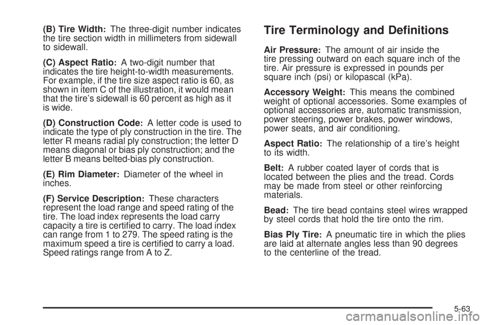
(B) Tire Width:The three-digit number indicates
the tire section width in millimeters from sidewall
to sidewall.
(C) Aspect Ratio
:A two-digit number that
indicates the tire height-to-width measurements.
For example, if the tire size aspect ratio is 60, as
shown in item C of the illustration, it would mean
that the tire’s sidewall is 60 percent as high as it
is wide.
(D) Construction Code
:A letter code is used to
indicate the type of ply construction in the tire. The
letter R means radial ply construction; the letter D
means diagonal or bias ply construction; and the
letter B means belted-bias ply construction.
(E) Rim Diameter
:Diameter of the wheel in
inches.
(F) Service Description
:These characters
represent the load range and speed rating of the
tire. The load index represents the load carry
capacity a tire is certi�ed to carry. The load index
can range from 1 to 279. The speed rating is the
maximum speed a tire is certi�ed to carry a load.
Speed ratings range from A to Z.
Tire Terminology and De�nitions
Air Pressure:The amount of air inside the
tire pressing outward on each square inch of the
tire. Air pressure is expressed in pounds per
square inch (psi) or kilopascal (kPa).
Accessory Weight
:This means the combined
weight of optional accessories. Some examples of
optional accessories are, automatic transmission,
power steering, power brakes, power windows,
power seats, and air conditioning.
Aspect Ratio
:The relationship of a tire’s height
to its width.
Belt
:A rubber coated layer of cords that is
located between the plies and the tread. Cords
may be made from steel or other reinforcing
materials.
Bead
:The tire bead contains steel wires wrapped
by steel cords that hold the tire onto the rim.
Bias Ply Tire
:A pneumatic tire in which the plies
are laid at alternate angles less than 90 degrees
to the centerline of the tread.
5-63
Page 392 of 490
Using the Tire Sealant and
Compressor Kit
Follow these directions closely for correct sealant
usage.
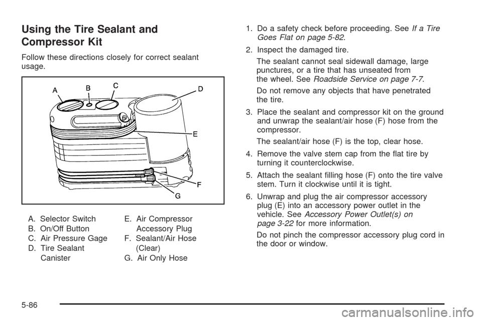
A. Selector Switch
B. On/Off Button
C. Air Pressure Gage
D. Tire Sealant
CanisterE. Air Compressor
Accessory Plug
F. Sealant/Air Hose
(Clear)
G. Air Only Hose1. Do a safety check before proceeding. SeeIf a Tire
Goes Flat on page 5-82.
2. Inspect the damaged tire.
The sealant cannot seal sidewall damage, large
punctures, or a tire that has unseated from
the wheel. SeeRoadside Service on page 7-7.
Do not remove any objects that have penetrated
the tire.
3. Place the sealant and compressor kit on the ground
and unwrap the sealant/air hose (F) hose from the
compressor.
The sealant/air hose (F) is the top, clear hose.
4. Remove the valve stem cap from the �at tire by
turning it counterclockwise.
5. Attach the sealant �lling hose (F) onto the tire valve
stem. Turn it clockwise until it is tight.
6. Unwrap and plug the air compressor accessory
plug (E) into an accessory power outlet in the
vehicle. SeeAccessory Power Outlet(s) on
page 3-22for more information.
Do not pinch the compressor accessory plug cord in
the door or window.
5-86
Page 402 of 490

7. Plug the air compressor accessory plug (C) into an
accessory power outlet in the vehicle. SeeAccessory
Power Outlet(s) on page 3-22for more information.
Do not slam door or close window on the
compressor accessory plug cord.
{CAUTION:
Idling the engine in a closed-in place or with
the climate control system off can cause
deadly carbon monoxide (CO). SeeEngine
Exhaust on page 2-48.
8. Start the vehicle. SeeStarting the Engine on
page 2-35for more information. The vehicle must
be running while using the air compressor.
{CAUTION:
Overin�ation could cause the tire to rupture,
and you or others could be injured. Be sure to
read the in�ator instructions, and in�ate the
tire to its recommended pressure. Do not
exceed 36 psi (248 kPa).
9. Push the On/Off switch to the I (on) position.
The tire sealant and compressor kit will inject
sealant and air into the tire.
The pressure gage (E) will initially show a high
pressure while the compressor pushes the sealant
into the tire. Once the sealant is completely
dispersed into the tire, the pressure will quickly drop
and start to rise again as the tire in�ates with air only.
5-96
Page 405 of 490

Using the Air Compressor without
Sealant to In�ate an Underin�ated Tire
(Not Punctured)
To use the air compressor to in�ate a tire with air only
and not sealant:
1. Unlock the air only (F) from the sealant canister (B)
by pulling up on the lever.
2. Pull the air only hose (F) from the sealant
canister (B).3. Remove the tire valve stem cap by turning it
counterclockwise.
4. Push the air only hose (F) onto the tire valve stem
and push the lever down to secure in place.
5. Remove the air compressor accessory plug (C)
from the unit.
6. Plug the air compressor accessory plug (C) into an
accessory power outlet in the vehicle. SeeAccessory
Power Outlet(s) on page 3-22for more information.
Do not slam the door or close the window on the
compressor accessory plug cord.
{CAUTION:
Idling the engine in a closed-in place or with
the climate control system off can cause
deadly carbon monoxide (CO). SeeEngine
Exhaust on page 2-48.
7. Start the vehicle. SeeStarting the Engine on
page 2-35for more information. The vehicle must
be running while using the air compressor.
5-99
Page 418 of 490

Appearance Care
Interior Cleaning
Your vehicle’s interior will continue to look its best if it is
cleaned often. Although not always visible, dust and dirt
can accumulate on your upholstery. Dirt can damage
carpet, fabric, leather, and plastic surfaces. Regular
vacuuming is recommended to remove particles from
your upholstery. It is important to keep your upholstery
from becoming and remaining heavily soiled. Soils should
be removed as quickly as possible. Your vehicle’s interior
may experience extremes of heat that could cause stains
to set rapidly.
Lighter colored interiors may require more frequent
cleaning. Use care because newspapers and garments
that transfer color to your home furnishings may also
transfer color to your vehicle’s interior.
When cleaning your vehicle’s interior, only use cleaners
speci�cally designed for the surfaces being cleaned.
Permanent damage may result from using cleaners on
surfaces for which they were not intended. Use glass
cleaner only on glass. Remove any accidental over-spray
from other surfaces immediately. To prevent over-spray,
apply cleaner directly to the cleaning cloth.Notice:If you use abrasive cleaners when cleaning
glass surfaces on your vehicle, you could scratch
the glass and/or cause damage to the rear window
defogger. When cleaning the glass on your
vehicle, use only a soft cloth and glass cleaner.
Many cleaners contain solvents that may become
concentrated in your vehicle’s breathing space.
Before using cleaners, read and adhere to all safety
instructions on the label. While cleaning your vehicle’s
interior, maintain adequate ventilation by opening
your vehicle’s doors and windows.
Dust may be removed from small buttons and knobs
using a small brush with soft bristles.
Your dealer/retailer has a product for cleaning your
vehicle’s glass. Should it become necessary, you can
also obtain a product from your dealer/retailer to remove
odors from your vehicle’s upholstery.
5-112
Page 428 of 490
Electrical System
Add-On Electrical Equipment
Notice:Do not add anything electrical to your
vehicle unless you check with your dealer/retailer
�rst. Some electrical equipment can damage
your vehicle and the damage would not be covered
by your warranty. Some add-on electrical equipment
can keep other components from working as they
should.
Add-on equipment can drain your vehicle’s battery, even
if your vehicle is not operating.
Your vehicle has an airbag system. Before attempting to
add anything electrical to your vehicle, seeServicing
Your Airbag-Equipped Vehicle on page 1-70.
Windshield Wiper Fuses
The windshield wiper motor is protected by an internal
circuit breaker. If the wiper motor overheats due to
heavy snow, the wipers will stop until the motor cools
and will then restart.
Power Windows and Other Power
Options
Circuit breakers in the fuse block protect the power
windows and other power accessories. When the current
load is too heavy, the circuit breaker opens and closes,
protecting the circuit until the problem is �xed or
goes away.
5-122
Page 433 of 490

Relays Usage
FUEL/PUMP Fuel Pump
LCK Lock
LF FRT/
PWR/SEATLeft Front Power Seat
LF/POS/LP Left Position LampRelays Usage
PWR CLMN Power Steering Column
PWR/WNDW Power Window
REAR/FOG Not Used
RT FRT/
PWR/SEATRight Front Power Seat
5-127
Page 434 of 490
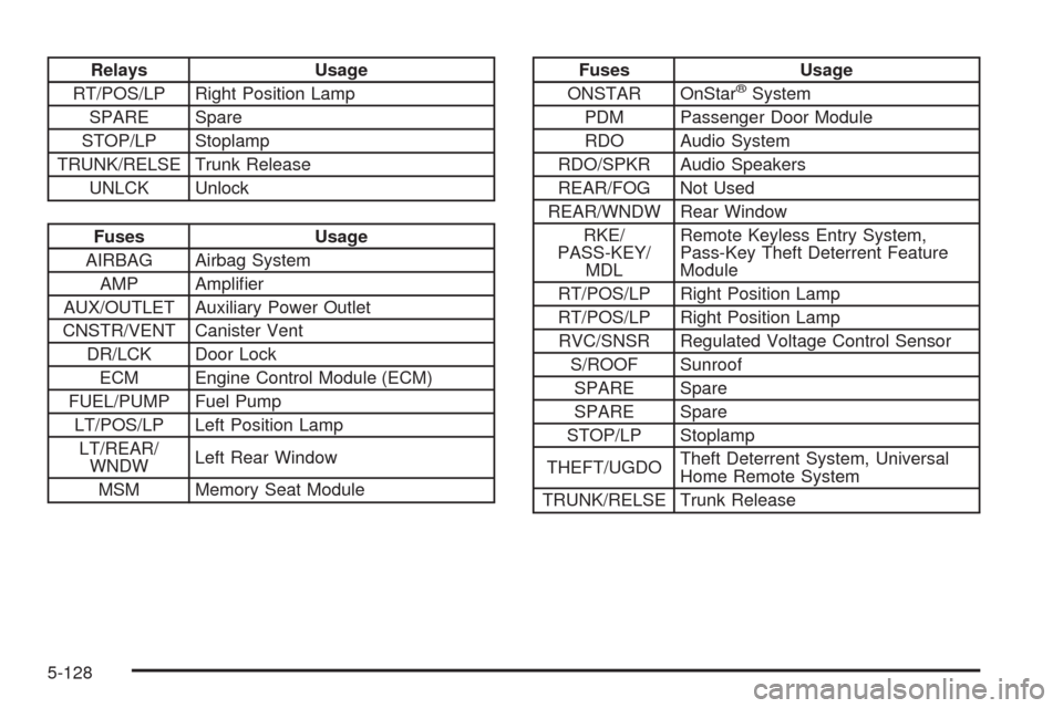
Relays Usage
RT/POS/LP Right Position Lamp
SPARE Spare
STOP/LP Stoplamp
TRUNK/RELSE Trunk Release
UNLCK Unlock
Fuses Usage
AIRBAG Airbag System
AMP Ampli�er
AUX/OUTLET Auxiliary Power Outlet
CNSTR/VENT Canister Vent
DR/LCK Door Lock
ECM Engine Control Module (ECM)
FUEL/PUMP Fuel Pump
LT/POS/LP Left Position Lamp
LT/REAR/
WNDWLeft Rear Window
MSM Memory Seat Module
Fuses Usage
ONSTAR OnStar®System
PDM Passenger Door Module
RDO Audio System
RDO/SPKR Audio Speakers
REAR/FOG Not Used
REAR/WNDW Rear Window
RKE/
PASS-KEY/
MDLRemote Keyless Entry System,
Pass-Key Theft Deterrent Feature
Module
RT/POS/LP Right Position Lamp
RT/POS/LP Right Position Lamp
RVC/SNSR Regulated Voltage Control Sensor
S/ROOF Sunroof
SPARE Spare
SPARE Spare
STOP/LP Stoplamp
THEFT/UGDOTheft Deterrent System, Universal
Home Remote System
TRUNK/RELSE Trunk Release
5-128
Page 480 of 490
Customer Assistance Information (cont.)
Customer Satisfaction Procedure..................... 7-2
GM Mobility Reimbursement Program............... 7-7
Reporting Safety Defects to General Motors.....7-17
Reporting Safety Defects to the
Canadian Government..............................7-17
Reporting Safety Defects to the
United States Government.........................7-16
Roadside Service.......................................... 7-7
Service Publications Ordering Information........7-17
D
Daytime Running Lamps..................................3-18
Defensive Driving............................................. 4-2
Delayed Locking.............................................2-19
DIC Compass.................................................3-53
Diesel
Running Out of Fuel....................................2-49
Disc, MP3....................................................3-106
Doing Your Own Service Work........................... 5-5
Door
Central Door Unlocking System.....................2-19
Delayed Locking..........................................2-19
Locks........................................................2-18
Power Door Locks.......................................2-19
Programmable Automatic Door Locks.............2-20
Rear Door Security Locks.............................2-20Driver Information Center (DIC).........................3-48
DIC Operation and Displays..........................3-48
DIC Vehicle Customization............................3-69
DIC Warnings and Messages........................3-56
Driving
At Night.....................................................4-14
Before a Long Trip......................................4-16
Defensive..................................................... 4-2
Drunken....................................................... 4-2
Highway Hypnosis.......................................4-16
Hill and Mountain Roads..............................4-16
In Rain and on Wet Roads...........................4-15
Rocking Your Vehicle to Get it Out.................4-22
Winter........................................................4-17
Dual Climate Control System............................3-24
E
EDR .............................................................7-18
Electrical System
Add-On Equipment.....................................5-122
Fuses and Circuit Breakers.........................5-123
Power Windows and Other Power Options....5-122
Rear Compartment Fuse Block....................5-126
Underhood Fuse Block...............................5-123
Windshield Wiper Fuses.............................5-122
4
Page 486 of 490
Power (cont.)
Lumbar Controls........................................... 1-6
Retained Accessory (RAP)............................2-35
Seat ............................................................ 1-5
Steering Fluid.............................................5-39
Tilt Wheel and Telescopic Steering Column....... 3-7
Windows....................................................2-25
Privacy..........................................................7-18
Event Data Recorders..................................7-19
Navigation System.......................................7-20
OnStar .......................................................7-20
Radio Frequency Identi�cation.......................7-20
Programmable Automatic Door Locks.................2-20
R
Radio Frequency Identi�cation (RFID), Privacy....7-20
Radio(s)........................................................3-83
Radios
Navigation/Radio System,
see Navigation Manual............................3-111
Reception.................................................3-125
Theft-Deterrent..........................................3-124
Rainsense™ Wipers........................................3-10
Reading Lamps..............................................3-21
Rear Axle......................................................5-51
Limited-Slip.................................................. 4-7
Rear Door Security Locks................................2-20Rearview Mirror, Automatic Dimming with
OnStar
®.....................................................2-50
Reclining Seatbacks.......................................... 1-8
Recommended Fluids and Lubricants.................6-14
Recreational Vehicle Towing.............................4-28
Remote, Keyless Access System........................ 2-9
Remote Keyless Entry (RKE) System.................. 2-6
Remote Keyless Entry (RKE) System, Operation . . . 2-7
Remote Vehicle Start.......................................2-16
Removing the Flat Tire and Installing the
Spare Tire................................................5-105
Removing the Spare Tire and Tools.................5-104
Replacement Bulbs.........................................5-57
Replacement Parts, Maintenance......................6-16
Reporting Safety Defects
Canadian Government..................................7-17
General Motors...........................................7-17
United States Government............................7-16
Restraint System Check
Checking the Restraint Systems....................1-72
Replacing Restraint System Parts
After a Crash..........................................1-73
Retained Accessory Power (RAP)......................2-35
Roadside
Service........................................................ 7-7
Rocking Your Vehicle to Get it Out....................4-22
Routing, Engine Drive Belt...............................6-17
Running Out of Fuel........................................2-49
10