CADILLAC CTS 2012 2.G Owners Manual
Manufacturer: CADILLAC, Model Year: 2012, Model line: CTS, Model: CADILLAC CTS 2012 2.GPages: 496, PDF Size: 6.36 MB
Page 121 of 496

Black plate (1,1)Cadillac CTS/CTS-V Owner Manual (Include Mex) - 2012
Storage 4-1
Storage
Storage Compartments
Instrument Panel Storage . . . . . 4-1
Glove Box . . . . . . . . . . . . . . . . . . . . 4-1
Cupholders . . . . . . . . . . . . . . . . . . . 4-1
Center Console Storage . . . . . . 4-2
Additional Storage Features
Cargo Cover (Wagon) . . . . . . . . . 4-2
Cargo Management System(Wagon Only) . . . . . . . . . . . . . . . . 4-3
Cargo Net (Wagon) . . . . . . . . . . . 4-4
Convenience Net (Sedan and Coupe) . . . . . . . . . . . . . . . . . . . . . . 4-6
Roof Rack System
Roof Rack System (Wagon) . . . 4-6
Storage
Compartments
Instrument Panel Storage
There is a storage area below the
climate control system. To access,
push the cover.
Glove Box
To open, press the button. Use the
key to lock and unlock. The glove
box has a shelf that can be removed
by pulling it out.
Cupholders
There are cupholders in the front of
the center console. Push the
cover (A) to open.
There are also cupholders in the
rear center armrest. Pull the armrest
down to use.
Page 122 of 496
Black plate (2,1)Cadillac CTS/CTS-V Owner Manual (Include Mex) - 2012
4-2 Storage
Center Console Storage
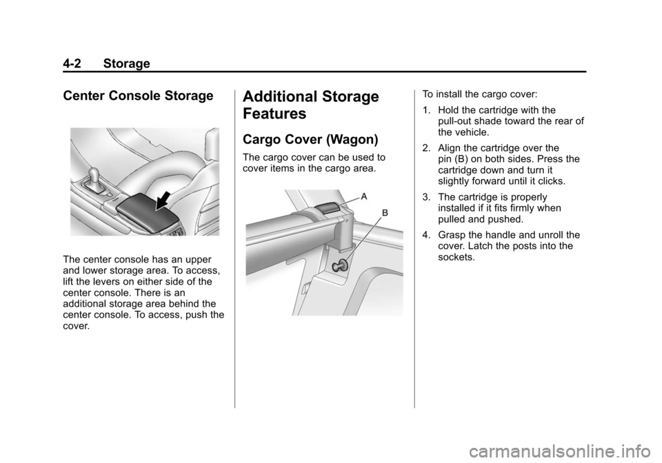
The center console has an upper
and lower storage area. To access,
lift the levers on either side of the
center console. There is an
additional storage area behind the
center console. To access, push the
cover.
Additional Storage
Features
Cargo Cover (Wagon)
The cargo cover can be used to
cover items in the cargo area.
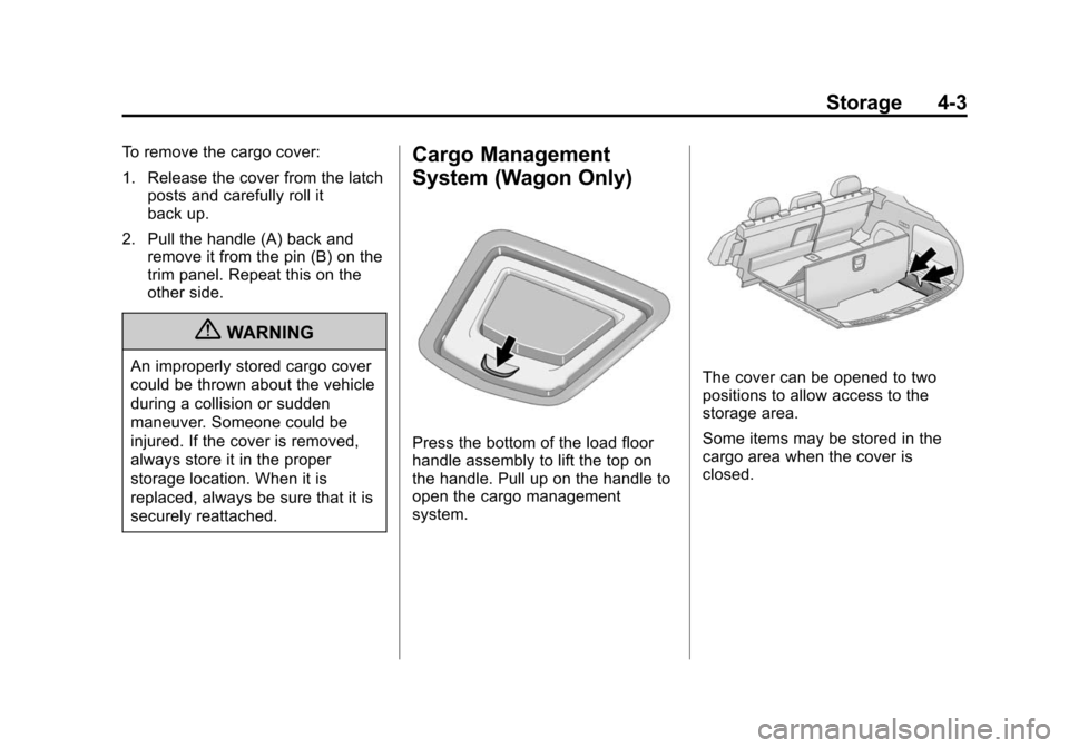
To install the cargo cover:
1. Hold the cartridge with thepull-out shade toward the rear of
the vehicle.
2. Align the cartridge over the pin (B) on both sides. Press the
cartridge down and turn it
slightly forward until it clicks.
3. The cartridge is properly installed if it fits firmly when
pulled and pushed.
4. Grasp the handle and unroll the cover. Latch the posts into the
sockets.
Page 123 of 496
Black plate (3,1)Cadillac CTS/CTS-V Owner Manual (Include Mex) - 2012
Storage 4-3
To remove the cargo cover:
1. Release the cover from the latchposts and carefully roll it
back up.
2. Pull the handle (A) back and remove it from the pin (B) on the
trim panel. Repeat this on the
other side.
{WARNING
An improperly stored cargo cover
could be thrown about the vehicle
during a collision or sudden
maneuver. Someone could be
injured. If the cover is removed,
always store it in the proper
storage location. When it is
replaced, always be sure that it is
securely reattached.
Cargo Management
System (Wagon Only)
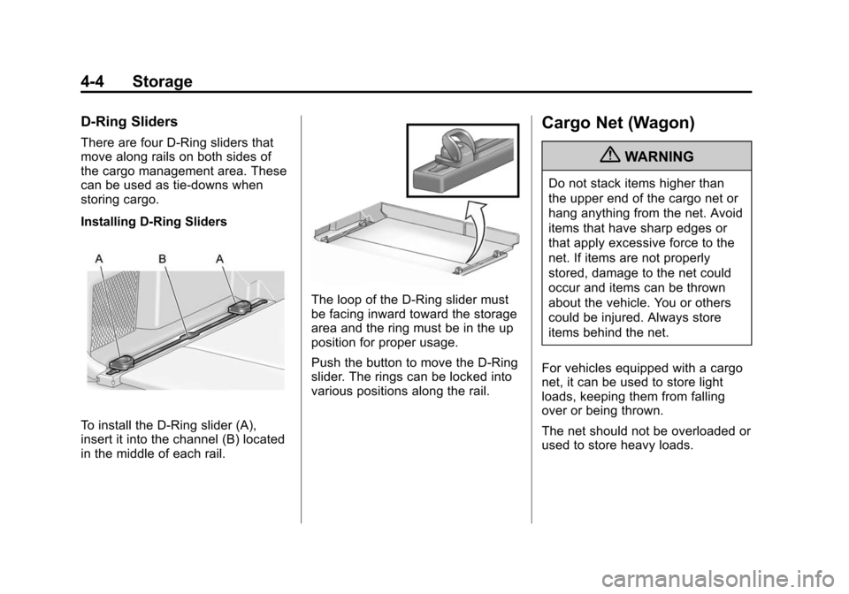
Press the bottom of the load floor
handle assembly to lift the top on
the handle. Pull up on the handle to
open the cargo management
system.
The cover can be opened to two
positions to allow access to the
storage area.
Some items may be stored in the
cargo area when the cover is
closed.
Page 124 of 496
Black plate (4,1)Cadillac CTS/CTS-V Owner Manual (Include Mex) - 2012
4-4 Storage
D-Ring Sliders
There are four D-Ring sliders that
move along rails on both sides of
the cargo management area. These
can be used as tie-downs when
storing cargo.
Installing D-Ring Sliders
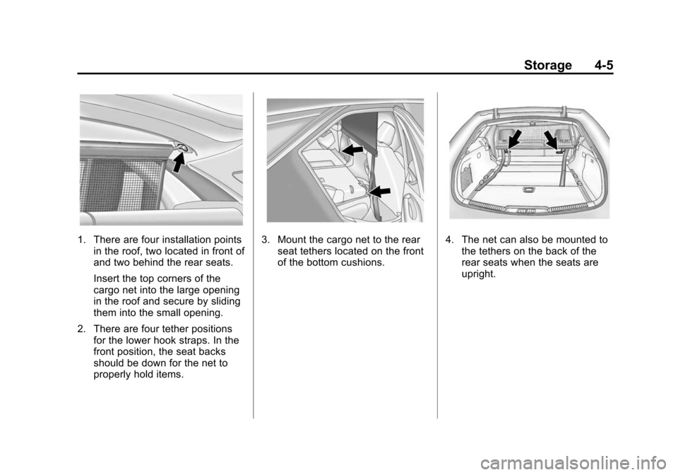
To install the D-Ring slider (A),
insert it into the channel (B) located
in the middle of each rail.
The loop of the D-Ring slider must
be facing inward toward the storage
area and the ring must be in the up
position for proper usage.
Push the button to move the D-Ring
slider. The rings can be locked into
various positions along the rail.
Cargo Net (Wagon)
{WARNING
Do not stack items higher than
the upper end of the cargo net or
hang anything from the net. Avoid
items that have sharp edges or
that apply excessive force to the
net. If items are not properly
stored, damage to the net could
occur and items can be thrown
about the vehicle. You or others
could be injured. Always store
items behind the net.
For vehicles equipped with a cargo
net, it can be used to store light
loads, keeping them from falling
over or being thrown.
The net should not be overloaded or
used to store heavy loads.
Page 125 of 496
Black plate (5,1)Cadillac CTS/CTS-V Owner Manual (Include Mex) - 2012
Storage 4-5
1. There are four installation pointsin the roof, two located in front of
and two behind the rear seats.
Insert the top corners of the
cargo net into the large opening
in the roof and secure by sliding
them into the small opening.
2. There are four tether positions for the lower hook straps. In the
front position, the seat backs
should be down for the net to
properly hold items.3. Mount the cargo net to the rearseat tethers located on the front
of the bottom cushions.4. The net can also be mounted tothe tethers on the back of the
rear seats when the seats are
upright.
Page 126 of 496

Black plate (6,1)Cadillac CTS/CTS-V Owner Manual (Include Mex) - 2012
4-6 Storage
5. Pull on the straps to tightenthe net.
Convenience Net (Sedan
and Coupe)
The vehicle may have a
convenience net in the rear. Put
small loads behind the net. It can
also be positioned into an envelope
style to hold smaller items. The net
is not for heavier loads. Store items
as far forward as you can.
Roof Rack System
Roof Rack System
(Wagon)
{WARNING
If something is carried on top of
the vehicle that is longer or wider
than the roof rack —like paneling,
plywood, or a mattress —the
wind can catch it while the vehicle
is being driven. The item being
carried could be violently torn off,
and this could cause a collision
and damage the vehicle. Never
carry something longer or wider
than the roof rack on top of the
vehicle unless using a GM
certified accessory carrier.
For vehicles with a roof rack, the
rack can be used to load items. For
roof racks that do not have
crossrails included, GM Certified crossrails can be purchased as an
accessory. See your dealer for
additional information.
Notice:
Loading cargo on the
roof rack that weighs more than
75 kg (165 lbs) or hangs over the
rear or sides of the vehicle may
damage the vehicle. Load cargo
so that it rests evenly between
the crossrails, making sure to
fasten cargo securely.
To prevent damage or loss of cargo
when driving, check to make sure
crossrails and cargo are securely
fastened. Loading cargo on the roof
rack will make the vehicle’ s center
of gravity higher. Avoid high speeds,
sudden starts, sharp turns, sudden
braking or abrupt maneuvers,
otherwise it may result in loss of
control. If driving for a long distance,
on rough roads, or at high speeds,
occasionally stop the vehicle to
make sure the cargo remains in its
place.
Page 127 of 496
Black plate (7,1)Cadillac CTS/CTS-V Owner Manual (Include Mex) - 2012
Storage 4-7
Do not exceed the maximum vehicle
capacity when loading the vehicle.
For more information on vehicle
capacity and loading, seeVehicle
Load Limits on page 9‑11.
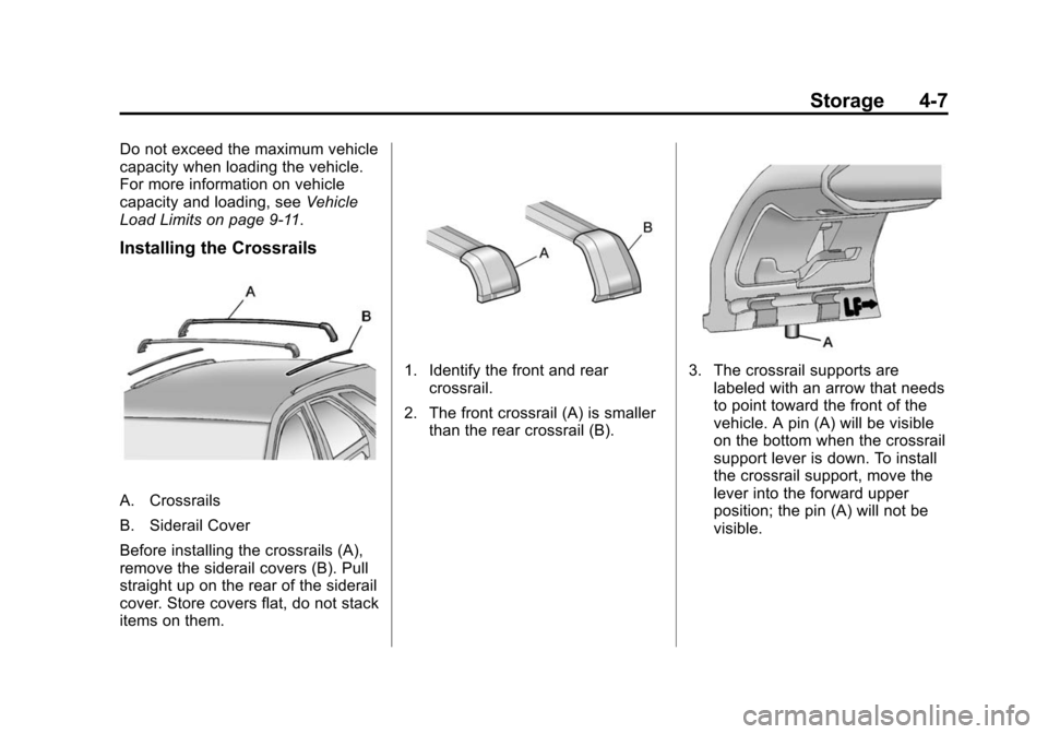
Installing the Crossrails
A. Crossrails
B. Siderail Cover
Before installing the crossrails (A),
remove the siderail covers (B). Pull
straight up on the rear of the siderail
cover. Store covers flat, do not stack
items on them.
1. Identify the front and rear crossrail.
2. The front crossrail (A) is smaller than the rear crossrail (B).3. The crossrail supports arelabeled with an arrow that needs
to point toward the front of the
vehicle. A pin (A) will be visible
on the bottom when the crossrail
support lever is down. To install
the crossrail support, move the
lever into the forward upper
position; the pin (A) will not be
visible.
Page 128 of 496
Black plate (8,1)Cadillac CTS/CTS-V Owner Manual (Include Mex) - 2012
4-8 Storage
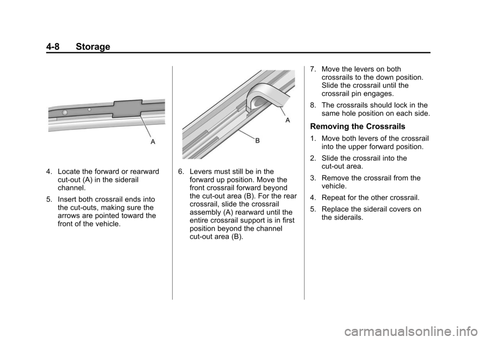
4. Locate the forward or rearwardcut-out (A) in the siderail
channel.
5. Insert both crossrail ends into the cut-outs, making sure the
arrows are pointed toward the
front of the vehicle.6. Levers must still be in theforward up position. Move the
front crossrail forward beyond
the cut-out area (B). For the rear
crossrail, slide the crossrail
assembly (A) rearward until the
entire crossrail support is in first
position beyond the channel
cut-out area (B). 7. Move the levers on both
crossrails to the down position.
Slide the crossrail until the
crossrail pin engages.
8. The crossrails should lock in the same hole position on each side.
Removing the Crossrails
1. Move both levers of the crossrail
into the upper forward position.
2. Slide the crossrail into the cut-out area.
3. Remove the crossrail from the vehicle.
4. Repeat for the other crossrail.
5. Replace the siderail covers on the siderails.
Page 129 of 496

Black plate (1,1)Cadillac CTS/CTS-V Owner Manual (Include Mex) - 2012
Instruments and Controls 5-1
Instruments and
Controls
Controls
Steering Wheel Adjustment . . . 5-2
Steering Wheel Controls . . . . . . 5-3
Heated Steering Wheel . . . . . . . 5-4
Horn . . . . . . . . . . . . . . . . . . . . . . . . . . 5-4
Windshield Wiper/Washer . . . . . 5-4
Rear Window Wiper/Washer . . . . . . . . . . . . . . . . . . . . . . 5-6
Headlamp Washer . . . . . . . . . . . . 5-7
Compass . . . . . . . . . . . . . . . . . . . . . 5-7
Clock . . . . . . . . . . . . . . . . . . . . . . . . . 5-8
Power Outlets . . . . . . . . . . . . . . . . . 5-9
Cigarette Lighter . . . . . . . . . . . . . . 5-9
Ashtrays . . . . . . . . . . . . . . . . . . . . . 5-10
Warning Lights, Gauges, and
Indicators
Warning Lights, Gauges, and Indicators . . . . . . . . . . . . . . . . . . 5-10
Instrument Cluster . . . . . . . . . . . 5-11
Speedometer . . . . . . . . . . . . . . . . 5-13
Odometer . . . . . . . . . . . . . . . . . . . . 5-13
Trip Odometer . . . . . . . . . . . . . . . 5-13
Tachometer . . . . . . . . . . . . . . . . . . 5-13 Fuel Gauge . . . . . . . . . . . . . . . . . . 5-13
Boost Gauge . . . . . . . . . . . . . . . . 5-14
Engine Speed Limiter . . . . . . . . 5-14
Engine Oil Pressure
Gauge . . . . . . . . . . . . . . . . . . . . . . 5-15
Engine Coolant Temperature Gauge . . . . . . . . . . . . . . . . . . . . . . 5-16
Safety Belt Reminders . . . . . . . 5-16
Airbag Readiness Light . . . . . . 5-17
Passenger Airbag Status Indicator . . . . . . . . . . . . . . . . . . . . 5-18
Charging System Light . . . . . . 5-19
Malfunction Indicator Lamp . . . . . . . . . . . . . 5-19
Brake System Warning Light . . . . . . . . . . . . . . . . . . . . . . . 5-22
Antilock Brake System (ABS) Warning Light . . . . . . . . . . . . . . 5-23
Up-Shift Light . . . . . . . . . . . . . . . . 5-23
StabiliTrak
®OFF Light . . . . . . . 5-23
Traction Control System (TCS)/StabiliTrak
®Light . . . . 5-24
Engine Coolant Temperature Warning Light . . . . . . . . . . . . . . 5-24
Tire Pressure Light . . . . . . . . . . 5-25
Engine Oil Pressure Light . . . . 5-25
Security Light . . . . . . . . . . . . . . . . 5-26
High-Beam On Light . . . . . . . . . 5-26 Front Fog Lamp Light . . . . . . . . 5-26
Lamps On Reminder . . . . . . . . . 5-26
Cruise Control Light . . . . . . . . . 5-27
Information Displays
Driver Information
Center (DIC) . . . . . . . . . . . . . . . 5-27
Vehicle Messages
Vehicle Messages . . . . . . . . . . . 5-31
Battery Voltage and ChargingMessages . . . . . . . . . . . . . . . . . . 5-31
Brake System Messages . . . . 5-32
Compass Messages . . . . . . . . . 5-34
Cruise Control Messages . . . . 5-34
Door Ajar Messages . . . . . . . . . 5-34
Engine Cooling System Messages . . . . . . . . . . . . . . . . . . 5-35
Engine Oil Messages . . . . . . . . 5-35
Engine Power Messages . . . . 5-36
Fuel System Messages . . . . . . 5-36
Key and Lock Messages . . . . . 5-37
Lamp Messages . . . . . . . . . . . . . 5-39
Object Detection System Messages . . . . . . . . . . . . . . . . . . 5-39
Ride Control System Messages . . . . . . . . . . . . . . . . . . 5-40
Airbag System Messages . . . . 5-43
Page 130 of 496
Black plate (2,1)Cadillac CTS/CTS-V Owner Manual (Include Mex) - 2012
5-2 Instruments and Controls
Anti-theft Alarm SystemMessages . . . . . . . . . . . . . . . . . . 5-43
Service Vehicle Messages . . . 5-43
Tire Messages . . . . . . . . . . . . . . . 5-43
Transmission Messages . . . . . 5-44
Vehicle Speed Messages . . . . 5-45
Washer Fluid Messages . . . . . 5-45
Vehicle Personalization
Vehicle Personalization . . . . . . 5-46
Universal Remote System
Universal Remote System . . . 5-53
Universal Remote System Programming . . . . . . . . . . . . . . . 5-53
Universal Remote System Operation . . . . . . . . . . . . . . . . . . 5-57
Controls
Steering Wheel
Adjustment
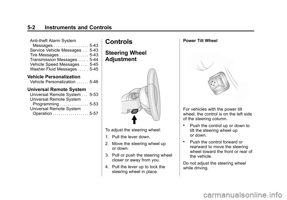
To adjust the steering wheel:
1. Pull the lever down.
2. Move the steering wheel up
or down.
3. Pull or push the steering wheel closer or away from you.
4. Pull the lever up to lock the steering wheel in place. Power Tilt Wheel
For vehicles with the power tilt
wheel, the control is on the left side
of the steering column.
.Push the control up or down to
tilt the steering wheel up
or down.
.Push the control forward or
rearward to move the steering
wheel toward the front or rear of
the vehicle.
Do not adjust the steering wheel
while driving.