clock CADILLAC CTS 2013 2.G User Guide
[x] Cancel search | Manufacturer: CADILLAC, Model Year: 2013, Model line: CTS, Model: CADILLAC CTS 2013 2.GPages: 478, PDF Size: 7.7 MB
Page 223 of 478
Black plate (35,1)Cadillac CTS/CTS-V Owner Manual - 2013 - crc2 - 8/22/12
Infotainment System 7-35
When a device is first connected to
the 3.5 mm (1/8 in) input jack or the
USB port (if equipped) the
infotainment system automatically
switches to that device. If an
auxiliary device has already been
connected, press the AUX or CD/
AUX button.
3.5 mm Jack
Connect a 3.5 mm (1/8 in) cable to
the auxiliary input jack to use a
portable audio player.
Playback of an audio device that is
connected to the 3.5 mm (1/8 in)
jack can only be controlled using
the controls on the device.
VOL/
O(Volume/Power):Turn
clockwise or counterclockwise to
increase or decrease the volume of
the portable player. Use the portable
device to make additional volume
adjustments.
CD or CD/AUX (CD/Auxiliary):
Press to play a CD when a portable
audio device is playing. Press again
to start playing audio from the connected portable audio player. If a
portable audio player is not
connected,
“No Aux Device”
displays.
USB Port
The USB connector uses the USB
standards, 1.1 and 2.0.
USB Supported Devices
.USB Flash Drives
.Portable USB Hard Drives
.Fifth generation or later iPods*
.First, Second, or Third
generation iPod nanos*
.iPod classics*
*For proper operation, make sure
the iPod has the latest firmware
from Apple
®. The iPod firmware can
be updated using the latest iTunes
application. See www.apple.com/
itunes. Connecting a USB Storage Device
Connect the USB storage device to
the USB port in the center console.
Some USB devices may not be
supported.
Playing an MP3/WMA from a USB
Storage Device
See
MP3 on page 7‑23 for more
information.
Connecting an iPod
To connect the iPod, connect one
end of the special iPod connection
cable to the iPod’s dock connector.
Connect the other end to both the
USB port and the auxiliary input jack
in the center console. The USB port
and the auxiliary input jack are in
the center console bin. If the vehicle
is on and the USB connection
works, a GM logo may appear on
the iPod. The iPod's music
information will be shown on the
radio’s display and the music begins
playing through the vehicle's audio
system.
Page 292 of 478

Black plate (50,1)Cadillac CTS/CTS-V Owner Manual - 2013 - crc2 - 8/22/12
9-50 Driving and Operating
WARNING (Continued)
.Fuel can spray out if the fuel
cap is opened too quickly.
This spray can happen if the
tank is nearly full, and is
more likely in hot weather.
Open the fuel cap slowly and
wait for any hiss noise to stop
then unscrew the cap all
the way
The cap is behind a locking fuel
door on the passenger side of the
vehicle.
To open the fuel door, push the
rearward center edge in and release
and it will open.
To remove the tethered fuel cap,
turn it slowly counterclockwise.
While refueling, hang the tethered
fuel cap from the hook on the
fuel door.
If the fuel cap is not installed
properly, a message will appear on
the Driver Information Center
display. SeeFuel System Messages
on page 5‑36.
When reinstalling the cap, turn it
clockwise until it clicks once,
otherwise the malfunction indicator
lamp could turn on. See Malfunction
Indicator Lamp on page 5‑19. Be careful not to spill fuel. Do not
top off or overfill the tank and wait a
few seconds after you have finished
pumping before removing the
nozzle. Clean fuel from painted
surfaces as soon as possible. See
Exterior Care on page 10‑105.
When replacing the fuel cap, turn it
clockwise until it clicks once. Make
sure the cap is fully installed. The
diagnostic system can determine if
the fuel cap has been left off or
improperly installed. This would
allow fuel to evaporate into the
atmosphere. See
Malfunction
Indicator Lamp on page 5‑19.
{WARNING
If a fire starts while you are
refueling, do not remove the
nozzle. Shut off the flow of fuel by
shutting off the pump or by
notifying the station attendant.
Leave the area immediately.
Page 319 of 478

Black plate (19,1)Cadillac CTS/CTS-V Owner Manual - 2013 - crc2 - 8/22/12
Vehicle Care 10-19
If coolant is needed, add the proper
DEX-COOL coolant mixture at the
coolant surge tank.
If no coolant is visible in the surge
tank, add coolant as follows:
1. Remove the coolant surge tankpressure cap when the cooling
system, including the coolant
surge tank pressure cap and
upper radiator hose, is no longer
hot. Turn the pressure cap
slowly counterclockwise about
one-quarter turn and then stop.
If you hear a hiss, wait for that to
stop. A hiss means there is still
some pressure left.
2. Keep turning the pressure capslowly and remove it.
3. Fill the coolant surge tank withthe proper mixture, to slightly
above the FROID/FULL COLD
line on the side of the coolant
surge tank.
4. With the coolant surge tank pressure cap off, start the
engine and let it run until you
can feel the upper radiator hose
getting hot. The upper radiator
hose is the top hose coming out
of the radiator, on the passenger
side of the vehicle. Watch out for
the engine cooling fans.
By this time, the coolant level
inside the coolant surge tank
may be lower. If the level is
lower, add more of the proper
mixture to the coolant surge tank
until the level reaches the
FROID/FULL COLD line on the
side of the coolant surge tank.
5. Replace the pressure cap. Be sure the pressure cap is
hand-tight and fully seated.
Page 320 of 478

Black plate (20,1)Cadillac CTS/CTS-V Owner Manual - 2013 - crc2 - 8/22/12
10-20 Vehicle Care
Notice:If the pressure cap is not
tightly installed, coolant loss and
possible engine damage may
occur. Be sure the cap is properly
and tightly secured.
Recheck the coolant level in the
bottle next time you use your
vehicle to ensure the system is full
when cold.
Checking Coolant in the
Intercooler System (CTS-V)
The vehicle must be on a level
surface when checking the coolant
level.
The super charged engine
intercooler coolant fill neck is in the
engine compartment on the
passenger side of the vehicle. See
Engine Compartment Overview on
page 10‑5.
On the coolant fill neck, there is a
cold fill region between the two
horizontal lines shown.
Check to see if coolant is visible in
the coolant fill neck. If the coolant is
not visible or below the cold fill region in the fill neck, add a 50/
50 mixture of clean, drinkable water
and DEX-COOL coolant at the
coolant fill bottle, but be sure the
cooling system is cool before this
is done.
Adding Coolant to the
Intercooler System
Coolant (CTS-V)
1. Remove the intercooler system
pressure cap when the
intercooler system hoses are no
longer hot. Turn the pressure
cap slowly counterclockwise about one-quarter of a turn.
If you hear a hiss, wait for that to
stop. This allows any pressure
still left to be vented.
2. Keep turning the pressure cap slowly and remove it.
3. Add the proper DEX-COOL coolant mixture to the fill neck
until the coolant is within the
cold fill region.
With the intercooler system
pressure cap off, start the
engine and let it run for a couple
of minutes. Then turn the engine
off. By this time, the coolant
level inside the fill neck may be
lower. If the level drops where
coolant is no longer within the
cold fill region of the fill neck
with the engine off, add more of
the DEX-COOL coolant mixture
to the fill neck until the level is
again visible in the cold fill
region.
4. Replace the pressure cap tightly.
Page 332 of 478
Black plate (32,1)Cadillac CTS/CTS-V Owner Manual - 2013 - crc2 - 8/22/12
10-32 Vehicle Care
High Intensity Discharge
(HID) Lighting
{WARNING
The high intensity discharge
lighting system operates at a very
high voltage. If you try to service
any of the system components,
you could be seriously injured.
Have your dealer or a qualified
technician service them.
After an HID headlamp bulb has
been replaced, the beam might be a
slightly different shade than it was
originally. This is normal.
LED Lighting
This vehicle has several LED lamps.
For replacement of any LED lighting
assembly, contact your dealer.
Fog Lamps
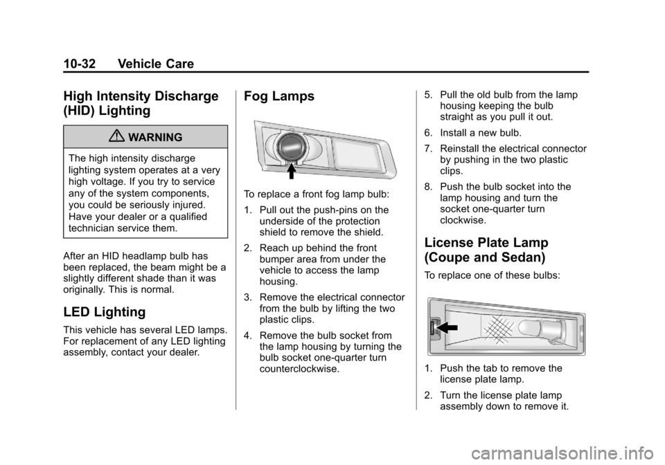
To replace a front fog lamp bulb:
1. Pull out the push-pins on the underside of the protection
shield to remove the shield.
2. Reach up behind the front bumper area from under the
vehicle to access the lamp
housing.
3. Remove the electrical connector from the bulb by lifting the two
plastic clips.
4. Remove the bulb socket from the lamp housing by turning the
bulb socket one-quarter turn
counterclockwise. 5. Pull the old bulb from the lamp
housing keeping the bulb
straight as you pull it out.
6. Install a new bulb.
7. Reinstall the electrical connector by pushing in the two plastic
clips.
8. Push the bulb socket into the lamp housing and turn the
socket one-quarter turn
clockwise.
License Plate Lamp
(Coupe and Sedan)
To replace one of these bulbs:
1. Push the tab to remove the
license plate lamp.
2. Turn the license plate lamp assembly down to remove it.
Page 333 of 478
Black plate (33,1)Cadillac CTS/CTS-V Owner Manual - 2013 - crc2 - 8/22/12
Vehicle Care 10-33
3. Turn the socketcounterclockwise and remove it.
4. Pull the bulb straight out to remove it.
5. Push the new bulb straight into the socket.
6. Reverse Steps 1 through 3 to reinstall the license plate lamp
assembly.
License Plate Lamp
(Wagon)
To replace one of these bulbs:
1. Open the liftgate. See Liftgate
on page 2‑19.
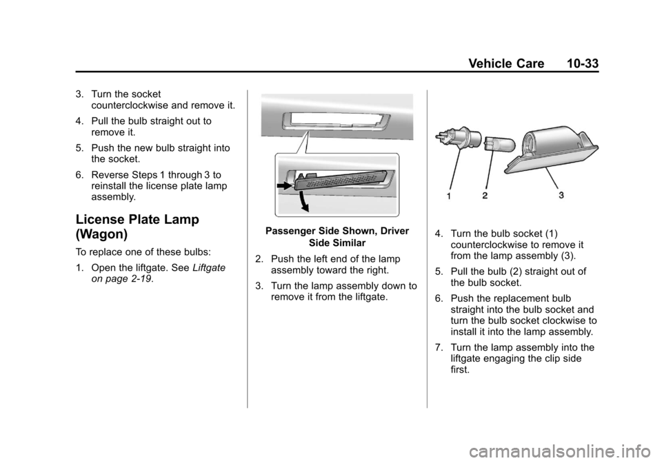
Passenger Side Shown, Driver
Side Similar
2. Push the left end of the lamp assembly toward the right.
3. Turn the lamp assembly down to remove it from the liftgate.4. Turn the bulb socket (1)counterclockwise to remove it
from the lamp assembly (3).
5. Pull the bulb (2) straight out of the bulb socket.
6. Push the replacement bulb straight into the bulb socket and
turn the bulb socket clockwise to
install it into the lamp assembly.
7. Turn the lamp assembly into the liftgate engaging the clip side
first.
Page 384 of 478
Black plate (84,1)Cadillac CTS/CTS-V Owner Manual - 2013 - crc2 - 8/22/12
10-84 Vehicle Care
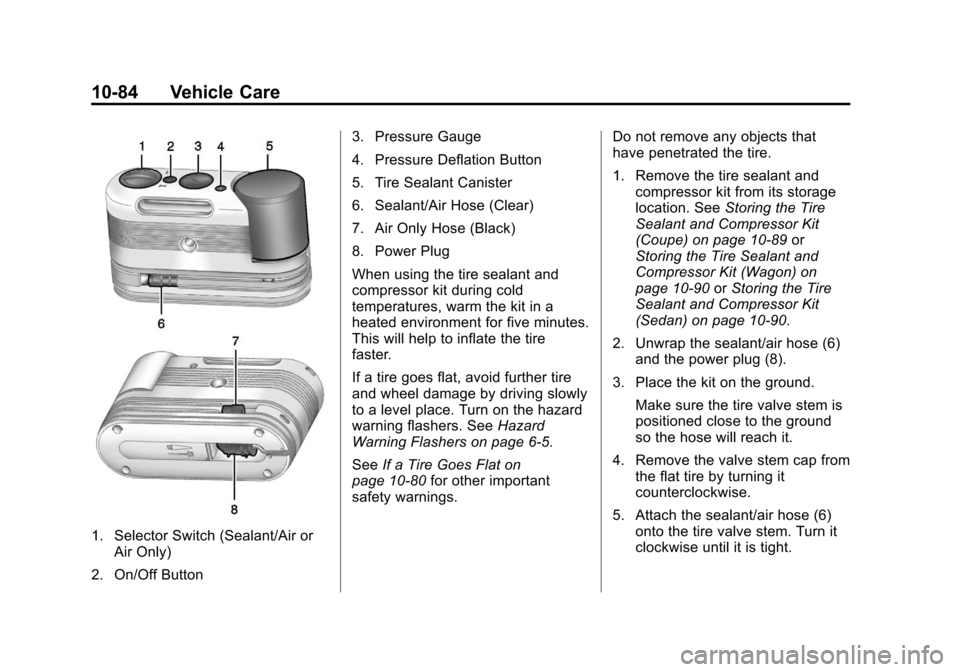
1. Selector Switch (Sealant/Air orAir Only)
2. On/Off Button 3. Pressure Gauge
4. Pressure Deflation Button
5. Tire Sealant Canister
6. Sealant/Air Hose (Clear)
7. Air Only Hose (Black)
8. Power Plug
When using the tire sealant and
compressor kit during cold
temperatures, warm the kit in a
heated environment for five minutes.
This will help to inflate the tire
faster.
If a tire goes flat, avoid further tire
and wheel damage by driving slowly
to a level place. Turn on the hazard
warning flashers. See
Hazard
Warning Flashers on page 6‑5.
See If a Tire Goes Flat on
page 10‑80 for other important
safety warnings. Do not remove any objects that
have penetrated the tire.
1. Remove the tire sealant and
compressor kit from its storage
location. See Storing the Tire
Sealant and Compressor Kit
(Coupe) on page 10‑89 or
Storing the Tire Sealant and
Compressor Kit (Wagon) on
page 10‑90 orStoring the Tire
Sealant and Compressor Kit
(Sedan) on page 10‑90.
2. Unwrap the sealant/air hose (6) and the power plug (8).
3. Place the kit on the ground. Make sure the tire valve stem is
positioned close to the ground
so the hose will reach it.
4. Remove the valve stem cap from the flat tire by turning it
counterclockwise.
5. Attach the sealant/air hose (6) onto the tire valve stem. Turn it
clockwise until it is tight.
Page 385 of 478
Black plate (85,1)Cadillac CTS/CTS-V Owner Manual - 2013 - crc2 - 8/22/12
Vehicle Care 10-85
6. Plug the power plug (8) into theaccessory power outlet in the
vehicle. Unplug all items from
other accessory power outlets.
See Power Outlets on page 5‑9.
If the vehicle has an accessory
power outlet, do not use the
cigarette lighter.
If the vehicle only has a cigarette
lighter, use the cigarette lighter.
Do not pinch the power plug
cord in the door or window.
7. Start the vehicle. The vehicle must be running while using the
air compressor.
8. Press and turn the selector switch (1) counterclockwise to
the Sealant + Air position.
9. Press the on/off button (2) to turn the tire sealant and
compressor kit on.
The compressor will inject
sealant and air into the tire. The pressure gauge (3) will
initially show a high pressure
while the compressor pushes the
sealant into the tire. Once the
sealant is completely dispersed
into the tire, the pressure will
quickly drop and start to rise
again as the tire inflates with
air only.
10. Inflate the tire to the recommended inflation
pressure using the pressure
gauge (3). The recommended
inflation pressure can be found
on the Tire and Loading
Information label. See Tire
Pressure on page 10‑66.
The pressure gauge (3) may
read higher than the actual tire
pressure while the compressor
is on. Turn the compressor off
to get an accurate pressure
reading. The compressor may
be turned on/off until the
correct pressure is reached. Notice:
If the recommended
pressure cannot be reached after
approximately 25 minutes, the
vehicle should not be driven
farther. The tire is too severely
damaged and the tire sealant and
compressor kit cannot inflate the
tire. Remove the power plug from
the accessory power outlet and
unscrew the inflating hose from
the tire valve. See Roadside
Service (U.S. and Canada) on
page 13‑7 orRoadside Service
(Mexico) on page 13‑9.
11. Press the on/off button (2) to turn the tire sealant and
compressor kit off.
The tire is not sealed and will
continue to leak air until the
vehicle is driven and the
sealant is distributed in the tire,
therefore, Steps 12–18 must be
done immediately after
Step 11.
Page 386 of 478

Black plate (86,1)Cadillac CTS/CTS-V Owner Manual - 2013 - crc2 - 8/22/12
10-86 Vehicle Care
Be careful while handling the
tire sealant and compressor kit
as it could be warm after
usage.
12. Unplug the power plug (8) from the accessory power outlet in
the vehicle.
13. Turn the sealant/air hose (6) counterclockwise to remove it
from the tire valve stem.
14. Replace the tire valve stem cap.
15. Replace the sealant/air hose (6), and the power plug (8)
back in their original location.
16. If the flat tire was able to inflateto the recommended inflation
pressure, remove the
maximum speed label from the sealant canister (5) and place it
in a highly visible location. Do
not exceed the speed on this
label until the damaged tire is
repaired or replaced.
17. Return the equipment to its original storage location in the
vehicle.
18. Immediately drive the vehicle 8 km (5 mi) to distribute the
sealant in the tire.
19. Stop at a safe location and check the tire pressure. Refer
to Steps 1–11 under “Using the
Tire Sealant and Compressor
Kit without Sealant to Inflate a
Tire (Not Punctured).”
If the tire pressure has fallen
more than 68 kPa (10 psi)
below the recommended
inflation pressure, stop driving
the vehicle. The tire is too
severely damaged and the tire
sealant cannot seal the tire. See
Roadside Service (U.S.
and Canada) on page 13‑7 or
Roadside Service (Mexico) on
page 13‑9.
If the tire pressure has not
dropped more than 68 kPa
(10 psi) from the recommended
inflation pressure, inflate the
tire to the recommended
inflation pressure.
20. Wipe off any sealant from the wheel, tire, and vehicle.
21. Dispose of the used sealant canister (5) and sealant/air
hose (6) assembly at a local
dealer or in accordance with
local state codes and practices.
22. Replace with a new canister assembly available from your
dealer.
Page 388 of 478

Black plate (88,1)Cadillac CTS/CTS-V Owner Manual - 2013 - crc2 - 8/22/12
10-88 Vehicle Care
2. Unwrap the air only hose (7) andthe power plug (8).
3. Place the kit on the ground. Make sure the tire valve stem is
positioned close to the ground
so the hose will reach it.
4. Remove the tire valve stem cap from the flat tire by turning it
counterclockwise.
5. Attach the air only hose (7) onto the tire valve stem by turning it
clockwise until it is tight.
6. Plug the power plug (8) into the accessory power outlet in the
vehicle. Unplug all items from
other accessory power outlets.
See Power Outlets on page 5‑9.
If the vehicle has an accessory
power outlet, do not use the
cigarette lighter.
If the vehicle only has a cigarette
lighter, use the cigarette lighter.
Do not pinch the power plug
cord in the door or window. 7. Start the vehicle. The vehicle
must be running while using the
air compressor.
8. Press and turn the selector switch (1) clockwise to the Air
Only position.
9. Press the on/off button (2) to turn the compressor on.
The compressor will inflate the
tire with air only.
10. Inflate the tire to the recommended inflation
pressure using the pressure
gauge (3). The recommended
inflation pressure can be found
on the Tire and Loading
Information label. See Tire
Pressure on page 10‑66.
The pressure gauge (3) may
read higher than the actual tire
pressure while the compressor
is on. Turn the compressor off
to get an accurate reading. The
compressor may be turned on/
off until the correct pressure is
reached. If you inflate the tire higher
than the recommended
pressure you can adjust the
excess pressure by pressing
the pressure deflation
button (4) until the proper
pressure reading is reached.
This option is only functional
when using the air only
hose (7).
11. Press the on/off button (2) to turn the tire sealant and
compressor kit off.
Be careful while handling the
tire sealant and compressor kit
as it could be warm after
usage.
12. Unplug the power plug (8) from the accessory power outlet in
the vehicle.
13. Disconnect the air only hose (7) from the tire valve stem, by
turning it counterclockwise, and
replace the tire valve stem cap.