fuses CADILLAC CTS V 2007 1.G Owners Manual
[x] Cancel search | Manufacturer: CADILLAC, Model Year: 2007, Model line: CTS V, Model: CADILLAC CTS V 2007 1.GPages: 518, PDF Size: 2.77 MB
Page 113 of 518

Testing the Alarm
1. Roll down the window, then get out of the
vehicle, keeping the door open.
2. From outside of the vehicle, with the door
open, lock the vehicle using the power door
lock switch or the RKE transmitter and close
the door. Wait approximately 30 seconds
until the security light goes off.
3. Reach in and unlock the door using the
manual lock and open the door. The horn
will sound and the exterior lamps will �ash.
The alarm can be turned off by unlocking the
driver’s door with the key, using the unlock button
on the RKE transmitter or by starting the car
with a valid key.
If the alarm does not sound when it should, check
to see if the horn works. The horn fuse may be
blown. To replace the fuse, seeFuses and Circuit
Breakers on page 447. If the fuse does not need
to be replaced, you may need to have your vehicle
serviced.
To reduce the possibility of theft, always arm the
theft-deterrent system when leaving your vehicle.
Immobilizer
This device complies with Part 15 of the FCC
Rules. Operation is subject to the following
two conditions:
1. This device may not cause interference.
2. This device must accept any interference
received, including interference that may
cause undesired operation.
This device complies with RSS-210 of Industry
Canada. Operation is subject to the following
two conditions:
1. This device may not cause interference.
2. This device must accept any interference
received, including interference that may
cause undesired operation of the device.
Changes or modi�cations to this system by other
than an authorized service facility could void
authorization to use this equipment.
113
Page 114 of 518

Immobilizer Operation
Your vehicle has a
passive theft-deterrent
system.
The system works when the key is turned to ON.
The key uses a transponder that matches an
immobilizer control unit in your vehicle. Only the
correct key will start the vehicle. If the key is ever
damaged, you may not be able to start your vehicle.When trying to start the vehicle, if the engine does
not start and the security light comes on, the
key may have a damaged transponder. Turn the
ignition off and try again.
If the engine still does not start, and the key
appears to be undamaged, try another ignition
key. At this time, you may also want to check
the fuse. SeeFuses and Circuit Breakers on
page 447. If the engine still does not start with the
other key, your vehicle needs service. If your
vehicle does start, the �rst key may be faulty.
See your dealer who can service the
theft-deterrent system and have a new key made.
It is possible for the theft-deterrent system decoder
to learn the transponder value of a new or
replacement key. Up to 10 additional keys may be
programmed for the vehicle. The following
procedure is for programming additional keys only.
114
Page 171 of 518

Turn Signal/Multifunction Lever
The lever on the left side of the steering column
includes the following:
GTurn and Lane-Change Signals. See
Turn and Lane-Change Signals on page 171.
OHeadlamps. SeeHeadlamps on page 180.
3Headlamp High/Low Beam-Changer.
SeeHeadlamp High/Low-Beam Changer
on page 172.
Flash-To-Pass Feature. SeeFlash-to-Pass on
page 172.
-Fog Lamps. SeeFog Lamps on page 183.
ICruise Control. SeeCruise Control on
page 176.
Turn and Lane-Change Signals
To signal a turn, move the lever all the way up or
down. The lever returns automatically when
the turn is complete.
An arrow on the
instrument panel
cluster �ashes in the
direction of the turn
or lane change.
Raise or lower the lever until the arrow starts to
�ash to signal a lane change. Hold it there until the
lane change is complete. The lever returns to its
original position when it is released.
Rapid �ashing of arrows when signaling for a turn
or lane change may be caused by a burned-out
signal bulb. Other driver’s will not see the signal.
Replace burned-out bulbs to help avoid possible
accidents. Check the fuse and for burned-out bulbs
if the arrow fails to work when signaling a turn.
SeeFuses and Circuit Breakers on page 447for
more information.
171
Page 187 of 518

There are two accessory power outlets. The front
accessory power outlet is located in the ashtray
on the instrument panel below the climate control
system. The outlet will have a cigarette lighter
if your vehicle has this option. Remove the
cigarette lighter to access the outlet.
The rear accessory power outlet is located on the
back of the center console.
To use an outlet, remove the protective cap.
When not in use, always cover the outlet with the
protective cap. The accessory power outlet is
operational at all times.
Notice:If electrical devices are left plugged
into a power outlet, the battery may drain
causing your vehicle not to start or damage to
the battery. This would not be covered by
the warranty. Always unplug all electrical
devices when turning off your vehicle.Certain electrical accessories may not be
compatible with the accessory power outlet and
could result in blown vehicle or adapter fuses.
If you experience a problem see your dealer for
additional information on accessory power outlets.
Notice:Adding any electrical equipment to
your vehicle may damage it or keep other
components from working as they should.
The repairs would not be covered by your
warranty. Do not use equipment exceeding
maximum amperage rating of 20 amperes.
Check with your dealer/retailer before adding
electrical equipment.
Notice:Improper use of the power outlet can
cause damage not covered by your warranty.
Do not hang any type of accessory or
accessory bracket from the plug because the
power outlets are designed for accessory
power plugs only.
187
Page 331 of 518

Sheet Metal Damage................................. 442
Finish Damage.......................................... 442
Underbody Maintenance............................ 443
Chemical Paint Spotting............................ 443
Vehicle Care/Appearance Materials............ 444
Vehicle Identi�cation.................................. 445
Vehicle Identi�cation Number (VIN)........... 445
Service Parts Identi�cation Label............... 445Electrical System........................................ 446
Add-On Electrical Equipment..................... 446
Windshield Wiper Fuses............................ 446
Power Windows and Other Power
Options.................................................. 446
Fuses and Circuit Breakers....................... 447
Underhood Fuse Block.............................. 447
Rear Underseat Fuse Block....................... 451
Capacities and Speci�cations.................... 457
Section 5 Service and Appearance Care
331
Page 375 of 518

Battery
Your vehicle has a maintenance free battery.
When it is time for a new battery, get one that has
the replacement number shown on the original
battery’s label. We recommend an ACDelco
®
replacement battery. SeeEngine Compartment
Overview on page 342for battery location.
Warning:Battery posts, terminals, and related
accessories contain lead and lead compounds,
chemicals known to the State of California
to cause cancer and reproductive harm. Wash
hands after handling.
{CAUTION:
Batteries have acid that can burn you and
gas that can explode. You can be badly
hurt if you are not careful. SeeJump
Starting on page 376for tips on working
around a battery without getting hurt.
After a power loss, such as disconnecting the
battery or removing the maxi fuses in the power
distribution fuse block, the following steps must be
performed to calibrate the electronic throttle control.
If this is not done, the engine will not run properly.
1. Turn the ignition key to ON. Do not start the
engine.
2. Leave the ignition in ON for at least
three minutes so that the electronic throttle
control will cycle and re-learn its home
position.
3. Turn the ignition to OFF.
4. Start and run the engine for at least
30 seconds.
375
Page 446 of 518

Electrical System
Add-On Electrical Equipment
Notice:Do not add anything electrical to your
vehicle unless you check with your dealer
�rst. Some electrical equipment can damage
your vehicle and the damage would not
be covered by your warranty. Some add-on
electrical equipment can keep other
components from working as they should.
Add-on equipment can drain your vehicle’s battery,
even if your vehicle is not operating.
Your vehicle has an airbag system. Before
attempting to add anything electrical to your
vehicle, seeServicing Your Airbag-Equipped
Vehicle on page 88.
Windshield Wiper Fuses
The windshield wiper motor is protected by an
internal circuit breaker. If the wiper motor
overheats due to heavy snow, the wipers will stop
until the motor cools and will then restart.
Power Windows and Other Power
Options
Circuit breakers protect the power windows and
power seats. When the current load is too
heavy, the circuit breaker opens and closes,
protecting the circuit until the problem is �xed or
goes away.
446
Page 447 of 518

Fuses and Circuit Breakers
The wiring circuits in your vehicle are protected
from short circuits by a combination of fuses
and circuit breakers. This greatly reduces
the chance of �res caused by electrical problems.
Look at the silver-colored band inside the fuse.
If the band is broken or melted, replace the fuse.
Be sure you replace a bad fuse with a new
one of the identical size and rating. If a fuse blows,
see your dealer for service immediately.
If you ever have a problem on the road and don’t
have a spare fuse, you can “borrow” one that has
the same amperage. Pick some feature of your
vehicle that you can get along without – like the
radio or cigarette lighter – and use its fuse, if it is the
correct amperage. Replace it as soon as you can.
The fuses are located in three fuse blocks,
one located in the engine compartment on the
passenger’s side and the other two under the
rear seat.
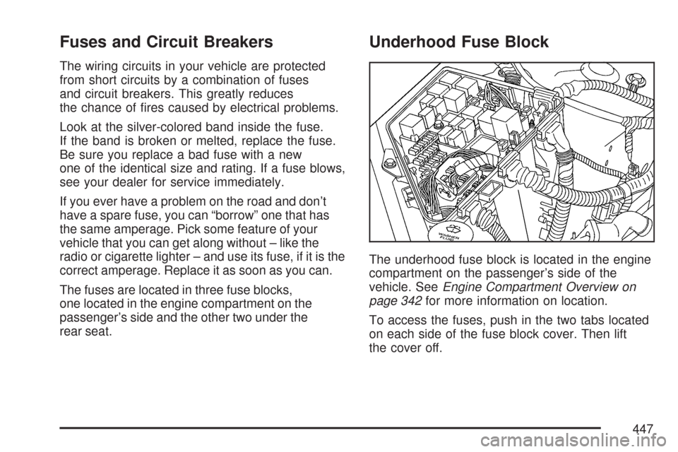
Underhood Fuse Block
The underhood fuse block is located in the engine
compartment on the passenger’s side of the
vehicle. SeeEngine Compartment Overview on
page 342for more information on location.
To access the fuses, push in the two tabs located
on each side of the fuse block cover. Then lift
the cover off.
447
Page 449 of 518

Wiring
HarnessesUsage
BODY W/H Wiring Harness Connection
BODY W/H Wiring Harness Connection
ENG W/H Engine Wiring Harness Connection
J Cases Usage
R REARRRPDB (Passenger’s Side Rear
Power Distribution Box)
R REARRRPDB (Passenger’s Side Rear
Power Distribution Box)
L REARLRPDB (Driver’s Side Rear Power
Distribution Box)
L REARLRPDB (Driver’s Side Rear Power
Distribution Box)
HI FAN High Cooling Fan Motor
LO FAN Low Cooling Fan Motor
BLOWER PWM Fan Motor Assembly
STARTER Starter Solenoid
ABS Anti-Lock Brake System
Fuses Usage
RT PARKPassenger’s Side Taillamp
Assembly, Front Sidemarker and
Front Parking Lamp Assembly
HORN Dual Horn Assembly
Fuses Usage
LT HI BEAM Driver’s Side High-Beam Headlamp
LT LOW BEAM Driver’s Side Low-Beam Headlamp
RT LOW BEAMPassenger’s Side Low-Beam
Headlamp
RT HI BEAMPassenger’s Side High-Beam
Headlamp
TOSManual Transmission Output Speed
Sensor
SPARE Not Used
THEFTECM (Engine Control Module),
TCM (Transmission Control Module),
PASS-Key
®III+ Module
LT PARKDriver’s Side Taillamp Assembly,
Front Sidemarker and Front Parking
Lamp Assembly
DIMMINGRear License Plate Assembly, Dash
Integrated Module (DIM)
DIM/ALDLDIM, ALDL (Assembly Line
Data Link)
FLASHER Turn Signal/Hazard Flasher Module
ECM Electronic Control Module
STRG CTLSTurn Signal Switch, Cruise Control
Switch
HTR VLV/
CLTCHClutch Switch (Normal Closed),
Clutch Switch (Normal Open),
Jumper to Start Relay Coil for
Automatic Transmission
449
Page 450 of 518

Fuses Usage
WASH NOZDriver’s and Passenger’s Side
Heated Washer Nozzles
PRE O2/CAMDriver’s & Passenger’s Side Oxygen
Sensors, CAM Phaser, Canister
Purge
TCM/IPCTransmission Control Module,
Engine Control Module, Instrument
Panel Cluster
SPARE Not Used
IGN MOD/MAF Mass Air�ow Sensor
ELEC PRNDL Electronic PRNDL (Export)
SPARE Not Used
SPARE Not Used
IGN SWIgnition Switch (Power to IGN-3 and
CRANK)
VOLT CHECK DIM (Dash Integration Module)
ECM/TCMTCM (Transmission Control Module),
ECM (Engine Control Module), IPC
(Instrument Panel Cluster),
PASS-Key
®III+ Module
WPR MOD Windshield Wiper Module Assembly
ODD INJ/COILOdd Ignition Coils, Fuel Injectors,
Odd Injection Coils
COMP CLUTCH Compressor Clutch
Fuses Usage
WPR SW Windshield Wiper/Washer Switch
FOG LAMP Fog Lamps
OUTLETCenter Console Accessory Power
Outlet
POST 02Driver’s and Passenger’s Side
Oxygen Sensors, LRPDB (Pusher
Cooling Fan Relay)
I/P OUTLETInstrument Panel Accessory Power
Outlet
CCP Climate Control
EVEN INJ/COIL Even Injection Coils
SPARE Not Used
SPARE Not Used
SPARE Not Used
SPARE Not Used
Circuit
BreakersUsage
HDLP WASH
C/B-OPTHeadlamp Washer Motor
Misc. Usage
FUSE PULLER Fuse Puller
450