engine CADILLAC ELR 2015 Manual PDF
[x] Cancel search | Manufacturer: CADILLAC, Model Year: 2015, Model line: ELR, Model: CADILLAC ELR 2015Pages: 407, PDF Size: 41.85 MB
Page 292 of 407

Black plate (31,1)Cadillac ELR Owner Manual (GMNA-Localizing-U.S./Canada-7695154) -
2015 - CRC - 4/25/14
Vehicle Care 10-31
Mini
Fuses Amps Usage
4 15A Ignition Coils/ Injectors
5 10A Column Lock
6a –Empty
6b –Empty
7 –Empty
8 –Empty
9 7.5A Heated Mirrors
10 5A Air Conditioning Control Module
11 7.5A Traction Power Inverter Module –
Battery
12 –Not Used
13 10A Cabin Heater Pump and Valve
14 –Not Used Mini
Fuses Amps Usage
15 15A Traction Power Inverter Module
and Transmission
Control Module –
Battery
17 5A Engine Control Module–Battery
22 10A Left High-Beam Headlamp
24 –Empty
25 –Empty
26 –Not Used
31 5A Adaptive Cruise Control/Auto
Headlamp
32 5A Vehicle Integration
Control Module
33 10A Run/Crank for Heated Steering
Wheel Mini
Fuses Amps Usage
34 10A Vehicle Integration
Control Module –
Battery
35 –Not Used
36 10A Power Electronics Coolant Pump
37 5A Cabin Heater Control Module
38 10A Rechargeable Energy Storage
System (High
Voltage Battery)
Coolant Pump
39 10A Rechargeable Energy Storage
System (High
Voltage Battery)
Control Module
40 10A Front Windshield Washer
ProCarManuals.com
Page 293 of 407
Black plate (32,1)Cadillac ELR Owner Manual (GMNA-Localizing-U.S./Canada-7695154) -
2015 - CRC - 4/25/14
10-32 Vehicle Care
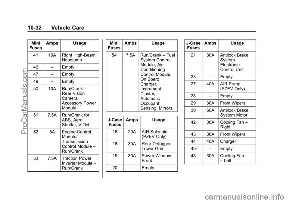
Mini
Fuses Amps Usage
41 10A Right High-Beam Headlamp
46 –Empty
47 –Empty
49 –Empty
50 10A Run/Crank –
Rear Vision
Camera,
Accessory Power
Module
51 7.5A Run/Crank for ABS, Aero
Shutter, VITM
52 5A Engine Control Module/
Transmission
Control Module –
Run/Crank
53 7.5A Traction Power Inverter Module –
Run/Crank Mini
Fuses Amps Usage
54 7.5A Run/Crank –Fuel
System Control
Module, Air
Conditioning
Control Module,
On Board
Charger,
Instrument
Cluster,
Automatic
Occupant
Sensing, Mirrors
J-Case Fuses Amps Usage
16 20A AIR Solenoid (PZEV Only)
18 30A Rear Defogger Lower Grid
19 30A Power Window –
Front
20 –Empty J-Case
Fuses Amps Usage
21 30A Antilock Brake System
Electronic
Control Unit
23 –Empty
27 40A AIR Pump (PZEV Only)
28 –Empty
29 30A Front Wipers
30 60A Antilock Brake System Motor
42 30A Cooling Fan –
Right
43 30A Front Wipers
44 40A Charger
45 –Empty
48 30A Cooling Fan –Left
ProCarManuals.com
Page 295 of 407

Black plate (34,1)Cadillac ELR Owner Manual (GMNA-Localizing-U.S./Canada-7695154) -
2015 - CRC - 4/25/14
10-34 Vehicle Care
A fuse puller is in the engine
compartment fuse block.
The vehicle may not be equipped
with all of the fuses, relays, and
features shown.Fuses Amps Usage
F1 20A Power Outlet/ Cigarette Lighter
–Top of IP
Storage Bin
F2 15A Infotainment (HMI, CD) Fuses Amps Usage
F3 10A Instrument Cluster
F4 10A Infotainment Display, Steering
Wheel Control
Switches
F5 10A Heating, Ventilation, & Air
Conditioning Fuses Amps Usage
F6 10A Airbag (Sensing Diagnostic
Module/
Passenger
Sensing Module)
F7 15A Data Link Connector, Left
(Primary)
F8 10A Column Lock
F9 10A OnStar
F10 15A Body Control Module 1/Body
Control Module
Electronics/
Keyless Entry/
Power Moding/
Center High
Mounted
Stoplamp/License
Plate Lamps/Left
Daytime Running
Lamp/Left
Parking Lamps/
Trunk Release
ProCarManuals.com
Page 297 of 407

Black plate (36,1)Cadillac ELR Owner Manual (GMNA-Localizing-U.S./Canada-7695154) -
2015 - CRC - 4/25/14
10-36 Vehicle Care
A fuse puller is in the engine
compartment fuse block.
The vehicle may not be equipped
with all of the fuses, relays, and
features shown.Fuses Amps Usage
F1 2A Steering Wheel Switch
F2 10A Auto Headlamp
Leveling Fuses Amps Usage
F3 10A Motorized Cup Holder
F4 15A Body Control Module 3/
Right
Headlamp Fuses Amps Usage
F5 7.5A Body Control Module 2/
Body Control
Module
Electronics/
Trunk Lamp/
Right
Daytime
Running
Lamp/Shifter
Lock/Switch
Backlighting
F6 15A Tilt/Telescope Column
F7 7.5A Body Control Module 6/
Map Lights/
Courtesy
Lights/Back-
up Lamp
ProCarManuals.com
Page 305 of 407
Black plate (44,1)Cadillac ELR Owner Manual (GMNA-Localizing-U.S./Canada-7695154) -
2015 - CRC - 4/25/14
10-44 Vehicle Care
resistance. For more information
seeUniform Tire Quality
Grading on page 10-57.
(7) Maximum Cold Inflation
Load Limit
:Maximum load that
can be carried and the
maximum pressure needed to
support that load.
Tire Designations
Tire Size
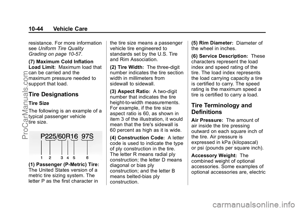
The following is an example of a
typical passenger vehicle
tire size.
(1) Passenger (P-Metric) Tire:
The United States version of a
metric tire sizing system. The
letter P as the first character in the tire size means a passenger
vehicle tire engineered to
standards set by the U.S. Tire
and Rim Association.
(2) Tire Width
:The three-digit
number indicates the tire section
width in millimeters from
sidewall to sidewall.
(3) Aspect Ratio
:A two-digit
number that indicates the tire
height-to-width measurements.
For example, if the tire size
aspect ratio is 60, as shown in
item 3 of the illustration, it would
mean that the tire's sidewall is
60 percent as high as it is wide.
(4) Construction Code
:A letter
code is used to indicate the type
of ply construction in the tire.
The letter R means radial ply
construction; the letter D means
diagonal or bias ply
construction; and the letter B
means belted-bias ply
construction. (5) Rim Diameter
:Diameter of
the wheel in inches.
(6) Service Description
:These
characters represent the load
index and speed rating of the
tire. The load index represents
the load carrying capacity a tire
is certified to carry. The speed
rating is the maximum speed a
tire is certified to carry a load.
Tire Terminology and
Definitions
Air Pressure:The amount of
air inside the tire pressing
outward on each square inch of
the tire. Air pressure is
expressed in kPa (kilopascal)
or psi (pounds per square inch).
Accessory Weight
:The
combined weight of optional
accessories. Some examples of
optional accessories are, electric
ProCarManuals.com
Page 322 of 407
Black plate (61,1)Cadillac ELR Owner Manual (GMNA-Localizing-U.S./Canada-7695154) -
2015 - CRC - 4/25/14
Vehicle Care 10-61
If a Tire Goes Flat
This vehicle has a tire sealant and
compressor kit. SeeTire Sealant
and Compressor Kit on page 10-62.
There is no spare tire, no tire
changing equipment, and no place
to store a tire.
To properly lift this vehicle, see
Lifting the Vehicle on page 10-3.
It is unusual for a tire to blowout
while driving, especially if the tires
are maintained properly. See Tires
on page 10-41. If air goes out of a
tire, it is much more likely to leak
out slowly. But if there ever is a
blowout, here are a few tips about
what to expect and what to do:
If a front tire fails, the flat tire will
create a drag that pulls the vehicle
toward that side. Take your foot off
the accelerator pedal and grip the
steering wheel firmly. Steer to
maintain lane position, and then
gently brake to a stop, well off the
road, if possible. A rear blowout, particularly on a
curve, acts much like a skid and
may require the same correction as
used in a skid. Stop pressing the
accelerator pedal and steer to
straighten the vehicle. It may be
very bumpy and noisy. Gently brake
to a stop, well off the road,
if possible.
{Warning
Driving on a flat tire will cause
permanent damage to the tire.
Re-inflating a tire after it has been
driven on while severely
underinflated or flat may cause a
blowout and a serious crash.
Never attempt to re-inflate a tire
that has been driven on while
severely underinflated or flat.
Have your dealer or an authorized
tire service center repair or
replace the flat tire as soon as
possible.
If a tire goes flat, avoid further tire
and wheel damage by driving slowly
to a level place and stopping, well
off the road, if possible.
1. Turn on the hazard warning
flashers. See Hazard Warning
Flashers on page 6-5.
2. Set the parking brake firmly.
3. Put the shift lever in P (Park). See Shifting Into Park on
page 9-19.
4. Turn off the engine.
5. Inspect the flat tire.
If the tire has been separated from
the wheel, has damaged sidewalls,
or has a puncture larger than
6 mm (0.25 in), the tire is too
severely damaged for the tire
sealant and compressor kit to be
effective. See Roadside Service on
page 13-5.
If the tire has a puncture less than
6 mm (0.25 in) in the tread area of
the tire, see Tire Sealant and
Compressor Kit on page 10-62.
ProCarManuals.com
Page 323 of 407
Black plate (62,1)Cadillac ELR Owner Manual (GMNA-Localizing-U.S./Canada-7695154) -
2015 - CRC - 4/25/14
10-62 Vehicle Care
Tire Sealant and
Compressor Kit
{Warning
Running the engine in Extended
Range Mode in an enclosed area
with poor ventilation is dangerous.
Engine exhaust may enter the
vehicle. Engine exhaust contains
carbon monoxide (CO) which
cannot be seen or smelled. It can
cause unconsciousness and even
death. Never run the engine in
Extended Range Mode in an
enclosed area that has no fresh
air ventilation. For more
information, seeEngine Exhaust
on page 9-27.
{Warning
Overinflating a tire could cause
the tire to rupture and you or
others could be injured. Be sure
to read and follow the tire sealant
and compressor kit instructions
and inflate the tire to its
recommended pressure. Do not
exceed the recommended
pressure.
{Warning
Storing the tire sealant and
compressor kit or other
equipment in the passenger
compartment of the vehicle could
cause injury. In a sudden stop or
collision, loose equipment could
strike someone. Store the tire
sealant and compressor kit in its
original location. If this vehicle has a tire sealant and
compressor kit, there may not be a
spare tire, tire changing equipment,
and on some vehicles there may not
be a place to store a tire.
The tire sealant and compressor
can be used to temporarily seal
punctures up to 6 mm (0.25 in) in
the tread area of the tire. It can also
be used to inflate an
underinflated tire.
If the tire has been separated from
the wheel, has damaged sidewalls,
or has a large puncture, the tire is
too severely damaged for the tire
sealant and compressor kit to be
effective. See
Roadside Service on
page 13-5.
Read and follow all of the tire
sealant and compressor kit
instructions.
ProCarManuals.com
Page 331 of 407
Black plate (70,1)Cadillac ELR Owner Manual (GMNA-Localizing-U.S./Canada-7695154) -
2015 - CRC - 4/25/14
10-70 Vehicle Care
Warning (Continued)
They contain electricity that can
burn. Follow the exact steps
provided or injuries could occur.
Using an open flame near a
battery can cause battery gas to
explode; you or others could be
hurt. Battery acid can cause
blindness.
Be sure the battery in the other
vehicle has enough water. Add
water if the level is low. A low
water level could cause explosive
gas to be present.
Battery fluid contains acid that
can burn. If battery fluid gets in
eyes or on skin; flush with water
and get medical help immediately.
{Warning
Electric fans can start up even
when the engine is not running
and can cause injury. Keep
hands, clothing, and tools away
from any underhood electric fans.
{Caution
Ignoring these steps could result
in costly damage to the vehicle
that would not be covered by the
vehicle warranty. Trying to start
the vehicle by pushing or pulling it
will not work, and it could damage
the vehicle.
Jump Starting the ELR
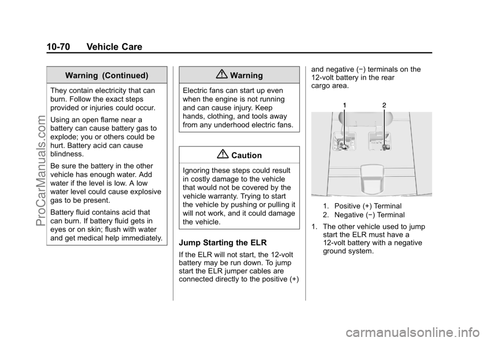
If the ELR will not start, the 12-volt
battery may be run down. To jump
start the ELR jumper cables are
connected directly to the positive (+)and negative (−) terminals on the
12-volt battery in the rear
cargo area.
1. Positive (+) Terminal
2. Negative (−) Terminal
1. The other vehicle used to jump
start the ELR must have a
12-volt battery with a negative
ground system.
ProCarManuals.com
Page 335 of 407

Black plate (74,1)Cadillac ELR Owner Manual (GMNA-Localizing-U.S./Canada-7695154) -
2015 - CRC - 4/25/14
10-74 Vehicle Care
6. Check that the jumper cables donot have loose or missing
insulation or a shock could result
and the vehicles could be
damaged.
Before connecting the jumper
cables, here are some basic
things to know. Positive (+)
jumper cable goes to positive (+)
battery terminal or a remote
positive (+) terminal if available.
Negative (−) jumper cable goes
to remote negative (−) terminal if
available, or a heavy, unpainted
metal engine part or a solid
engine ground on the vehicle
with the run-down battery.
Do not connect positive (+) to
negative (−) or there will be a
short that may damage the
battery or other parts of the
vehicle. Do not connect the
negative (−) cable to the
negative (−) terminal on the
run-down battery because this
can cause sparks.{Caution
If the jumper cables are
connected or removed in the
wrong order, electrical shorting
may occur and damage the
vehicle. The repairs would not be
covered by the vehicle warranty.
Always connect and remove the
jumper cables in the correct order,
making sure that the cables do
not touch each other or other
metal.
Connecting the Jumper Cables
1. Connect the red positive (+) jumper cable to the positive (+)
terminal of the other vehicle with
the run-down battery. Use a
remote positive (+) terminal if
available. Do not let the other
end touch metal.
2. Connect the other end of the red positive (+) jumper cable to the
positive (+) battery terminal of
the ELR. 3. Connect the black negative (−)
jumper cable to the negative (−)
battery terminal of the ELR. Do
not let the other end touch
anything until the next step.
4. Make the final connection to a heavy, unpainted metal engine
part or to the remote negative
(−) terminal on the other vehicle
with the run-down battery.
5. Press the POWER
Obutton to
start the ELR. This will wake up
the electronics on the ELR. The
engine will only start if it is
needed.
6. Try to start the other vehicle that had the run-down battery. If it
will not start after a few tries, it
probably needs service.
Disconnecting the Jumper Cables
1. Disconnect the black negative (−) jumper cable from the other
vehicle that had the run-down
battery. Do not let the other end
of the cable touch anything until
after the next step.
ProCarManuals.com
Page 351 of 407

Black plate (2,1)Cadillac ELR Owner Manual (GMNA-Localizing-U.S./Canada-7695154) -
2015 - CRC - 4/25/14
11-2 Service and Maintenance
Because of the way people use
vehicles, maintenance needs vary.
There may need to be more
frequent checks and services. The
Additional Required Services -
Normal are for vehicles that:
.Carry passengers and cargo
within recommended limits on
the Tire and Loading Information
label. SeeVehicle Load Limits
on page 9-12.
.Are driven on reasonable road
surfaces within legal driving
limits.
.Use the recommended fuel. See
Fuel on page 9-67.
Refer to the information in the
Maintenance Schedule Additional
Required Services - Normal chart.
The Additional Required Services -
Severe are for vehicles that are:
.Mainly driven in heavy city traffic
in hot weather.
.Mainly driven in hilly or
mountainous terrain.
.Frequently towing a trailer.
.Used for high speed or
competitive driving.
.Used for taxi, police, or delivery
service.
Refer to the information in the
Maintenance Schedule Additional
Required Services - Severe chart.
{Warning
Performing maintenance work can
be dangerous and can cause
serious injury. Perform
maintenance work only if the
required information, proper tools,
and equipment are available.
If they are not, see your dealer to
have a trained technician do the
work. See Doing Your Own
Service Work on page 10-5.
Maintenance
Schedule
Owner Checks and Services
At Each Fuel Stop
.Check the engine oil level. See
Engine Oil on page 10-9.
Once a Month
.Check the tire inflation
pressures. See Tire Pressure on
page 10-47.
.Inspect the tires for wear. See
Tire Inspection on page 10-53.
.Check the windshield washer
fluid level. See Washer Fluid on
page 10-19.
.Engine, power electronics, and
high voltage battery pack
coolant level checks. See
Cooling System (Engine) on
page 10-14 orCooling System
(High Voltage Battery) on
page 10-15 orCooling System
(Power Electronics and Charger
Modules) on page 10-16.
ProCarManuals.com