tow CADILLAC ESCALADE EXT 2008 3.G Workshop Manual
[x] Cancel search | Manufacturer: CADILLAC, Model Year: 2008, Model line: ESCALADE EXT, Model: CADILLAC ESCALADE EXT 2008 3.GPages: 496, PDF Size: 7.02 MB
Page 325 of 496
Parking on Hills
{CAUTION:
You really should not park your vehicle, with a
trailer attached, on a hill. If something goes
wrong, your rig could start to move. People
can be injured, and both your vehicle and the
trailer can be damaged.
But if you ever have to park your rig on a hill, here’s
how to do it:
1. Apply your regular brakes, but don’t shift into
PARK (P) yet.
2. Have someone place chocks under the trailer
wheels.
3. When the wheel chocks are in place, release the
regular brakes until the chocks absorb the load.
4. Reapply the regular brakes. Then apply your
parking brake and shift into PARK (P).
5. Release the regular brakes.
When You Are Ready to Leave After
Parking on a Hill
1. Apply your regular brakes and hold the pedal down
while you:
start your engine,
shift into a gear, and
release the parking brake.
2. Let up on the brake pedal.
3. Drive slowly until the trailer is clear of the chocks.
4. Stop and have someone pick up and store the
chocks.
Maintenance When Trailer Towing
Your vehicle will need service more often when you’re
pulling a trailer. See the Maintenance Schedule for more
on this. Things that are especially important in trailer
operation are automatic transmission �uid (don’t over�ll
or under�ll), engine oil, axle lubricant, belts, cooling
system and brake system. Each of these is covered in
this manual, and the Index will help you �nd them
quickly. If you’re trailering, it’s a good idea to review these
sections before you start your trip.
Check periodically to see that all hitch nuts and bolts
are tight.
4-53
Page 326 of 496
Trailer Wiring Harness
Heavy-Duty Trailer Wiring Package
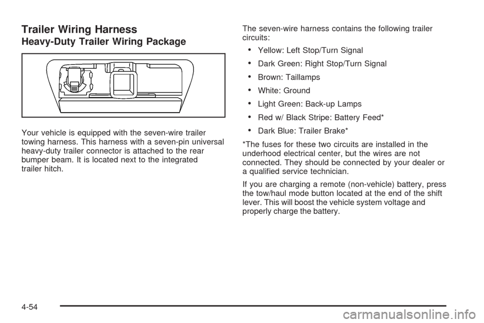
Your vehicle is equipped with the seven-wire trailer
towing harness. This harness with a seven-pin universal
heavy-duty trailer connector is attached to the rear
bumper beam. It is located next to the integrated
trailer hitch.The seven-wire harness contains the following trailer
circuits:
Yellow: Left Stop/Turn Signal
Dark Green: Right Stop/Turn Signal
Brown: Taillamps
White: Ground
Light Green: Back-up Lamps
Red w/ Black Stripe: Battery Feed*
Dark Blue: Trailer Brake*
*The fuses for these two circuits are installed in the
underhood electrical center, but the wires are not
connected. They should be connected by your dealer or
a quali�ed service technician.
If you are charging a remote (non-vehicle) battery, press
the tow/haul mode button located at the end of the shift
lever. This will boost the vehicle system voltage and
properly charge the battery.
4-54
Page 327 of 496
Electric Brake Control Wiring
Provisions
These wiring provisions are included with your vehicle
as part of the heavy-duty trailer wiring package.
These provisions are for an electric brake controller.
The red/black stripe power feed will not be connected
to the battery until the ring terminal is unstowed and
connected to the underhood electrical center. The
instrument panel contains blunt cut wires near the
data link connector for the trailer brake controller.
The harness contains the following wires:
Dark Blue: Auxiliary
Red/Black: Battery
Light Blue/White: Brake Switch
White: Ground
It should be installed by your dealer or a quali�ed
service center.
Trailer Recommendations
You must subtract your hitch loads from the Cargo
Weight Rating (CWR). CWR is the maximum weight of
the load your vehicle can carry. It doesn’t include the
weight of the people inside, but you can �gure about
150 lbs. (68 kg) for each seat. The total cargo load must
not be more than your vehicles CWR.
Weigh your vehicle with your trailer attached, so that
you won’t go over the GVWR or GAWR. If you are using
a weight-distributing hitch, weigh the vehicle without the
spring bars in place.
You’ll get the best performance if you spread out the
weight of your load the right way, and if you choose the
correct hitch and trailer brakes.
For more information seeTowing a Trailer on page 4-43.
4-55
Page 341 of 496
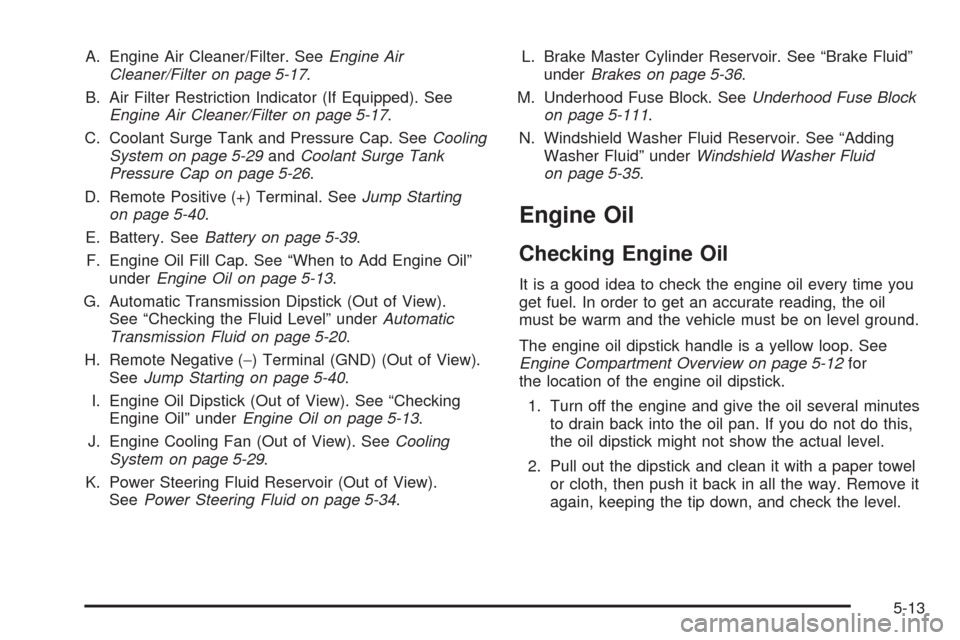
A. Engine Air Cleaner/Filter. SeeEngine Air
Cleaner/Filter on page 5-17.
B. Air Filter Restriction Indicator (If Equipped). See
Engine Air Cleaner/Filter on page 5-17.
C. Coolant Surge Tank and Pressure Cap. SeeCooling
System on page 5-29andCoolant Surge Tank
Pressure Cap on page 5-26.
D. Remote Positive (+) Terminal. SeeJump Starting
on page 5-40.
E. Battery. SeeBattery on page 5-39.
F. Engine Oil Fill Cap. See “When to Add Engine Oil”
underEngine Oil on page 5-13.
G. Automatic Transmission Dipstick (Out of View).
See “Checking the Fluid Level” underAutomatic
Transmission Fluid on page 5-20.
H. Remote Negative (−) Terminal (GND) (Out of View).
SeeJump Starting on page 5-40.
I. Engine Oil Dipstick (Out of View). See “Checking
Engine Oil” underEngine Oil on page 5-13.
J. Engine Cooling Fan (Out of View). SeeCooling
System on page 5-29.
K. Power Steering Fluid Reservoir (Out of View).
SeePower Steering Fluid on page 5-34.L. Brake Master Cylinder Reservoir. See “Brake Fluid”
underBrakes on page 5-36.
M. Underhood Fuse Block. SeeUnderhood Fuse Block
on page 5-111.
N. Windshield Washer Fluid Reservoir. See “Adding
Washer Fluid” underWindshield Washer Fluid
on page 5-35.
Engine Oil
Checking Engine Oil
It is a good idea to check the engine oil every time you
get fuel. In order to get an accurate reading, the oil
must be warm and the vehicle must be on level ground.
The engine oil dipstick handle is a yellow loop. See
Engine Compartment Overview on page 5-12for
the location of the engine oil dipstick.
1. Turn off the engine and give the oil several minutes
to drain back into the oil pan. If you do not do this,
the oil dipstick might not show the actual level.
2. Pull out the dipstick and clean it with a paper towel
or cloth, then push it back in all the way. Remove it
again, keeping the tip down, and check the level.
5-13
Page 348 of 496
Automatic Transmission Fluid
When to Check and Change Automatic
Transmission Fluid
It is usually not necessary to check the transmission
�uid level. The only reason for �uid loss is a
transmission leak or overheating the transmission. If you
suspect a small leak, then use the following checking
procedures to check the �uid level. However, if there is a
large leak, then it may be necessary to have the
vehicle towed to a dealer/retailer service department
and have it repaired before driving the vehicle further.
Notice:Use of the incorrect automatic transmission
�uid may damage your vehicle, and the damages
may not be covered by your warranty. Always
use the automatic transmission �uid listed in
Recommended Fluids and Lubricants on page 6-13.
Change the �uid and �lter at the intervals listed in
the Maintenance Schedule. SeeScheduled Maintenance
on page 6-4. Be sure to use the transmission �uid
listed inRecommended Fluids and Lubricants on
page 6-13.
How to Check Automatic
Transmission Fluid
Notice:Too much or too little �uid can damage
your transmission. Too much can mean that some
of the �uid could come out and fall on hot engine
parts or exhaust system parts, starting a �re.
Too little �uid could cause the transmission to
overheat. Be sure to get an accurate reading if you
check your transmission �uid.
Before checking the �uid level, prepare your vehicle as
follows:
1. Start the engine and park your vehicle on a level
surface. Keep the engine running.
2. Apply the parking brake and place the shift lever in
PARK (P).
3. With your foot on the brake pedal, move the shift
lever through each gear range, pausing for about
three seconds in each range. Then, move the
shift lever back to PARK (P).
4. Allow the engine to idle (500 – 800 rpm) for at least
one minute. Slowly release the brake pedal.
5-20
Page 349 of 496

5. Keep the engine running and press the Trip/Fuel
button or trip odometer reset stem until TRANS
TEMP (Transmission Temperature) displays on the
Driver Information Center (DIC).
6. Using the TRANS TEMP reading, determine and
perform the appropriate check procedure. If the
TRANS TEMP reading is not within the required
temperature ranges, allow the vehicle to cool,
or operate the vehicle until the appropriate
transmission �uid temperature is reached.
Cold Check Procedure
Use this procedure only as a reference to determine if
the transmission has enough �uid to be operated
safely until a hot check procedure can be made. The
hot check procedure is the most accurate method
to check the �uid level. Perform the hot check procedure
at the �rst opportunity. Use this cold check procedure
to check �uid level when the transmission temperature is
between 80°F and 90°F (27°C and 32°C).
1. Locate the transmission dipstick at the rear of
the engine compartment, on the passenger side
of the vehicle.The dipstick handle has
this graphic. SeeEngine
Compartment Overview
on page 5-12for more
information.
2. Flip the handle up, and then pull out the dipstick
and wipe it with a clean rag or paper towel.
3. Install the dipstick by pushing it back in all the way,
wait three seconds, and then pull it back out again.
4. Check both sides of the dipstick, and read the lower
level. Repeat the check procedure to verify the
reading.
5-21
Page 350 of 496
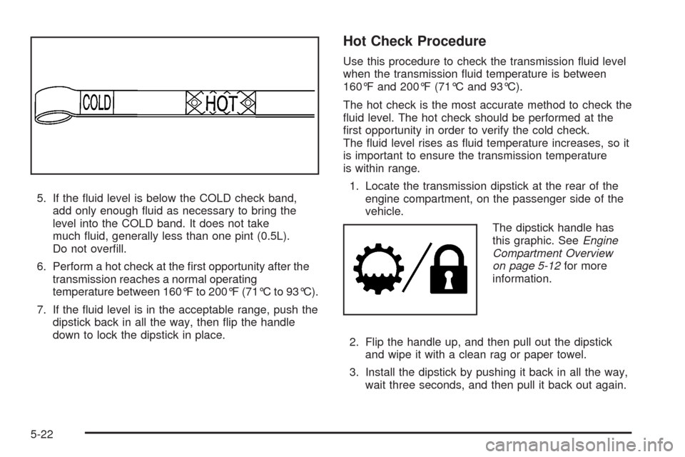
5. If the �uid level is below the COLD check band,
add only enough �uid as necessary to bring the
level into the COLD band. It does not take
much �uid, generally less than one pint (0.5L).
Do not over�ll.
6. Perform a hot check at the �rst opportunity after the
transmission reaches a normal operating
temperature between 160°F to 200°F (71°C to 93°C).
7. If the �uid level is in the acceptable range, push the
dipstick back in all the way, then �ip the handle
down to lock the dipstick in place.
Hot Check Procedure
Use this procedure to check the transmission �uid level
when the transmission �uid temperature is between
160°F and 200°F (71°C and 93°C).
The hot check is the most accurate method to check the
�uid level. The hot check should be performed at the
�rst opportunity in order to verify the cold check.
The �uid level rises as �uid temperature increases, so it
is important to ensure the transmission temperature
is within range.
1. Locate the transmission dipstick at the rear of the
engine compartment, on the passenger side of the
vehicle.
The dipstick handle has
this graphic. SeeEngine
Compartment Overview
on page 5-12for more
information.
2. Flip the handle up, and then pull out the dipstick
and wipe it with a clean rag or paper towel.
3. Install the dipstick by pushing it back in all the way,
wait three seconds, and then pull it back out again.
5-22
Page 355 of 496
Notice:If your engine catches �re because you
keep driving with no coolant, your vehicle can
be badly damaged. The costly repairs would not be
covered by your warranty. SeeOverheated Engine
Protection Operating Mode on page 5-28for
information on driving to a safe place in an
emergency.
If No Steam Is Coming From
Your Engine
The ENGINE OVERHEATED STOP ENGINE or the
ENGINE OVERHEATED IDLE ENGINE message,
along with a low coolant condition, can indicate a serious
problem.
If you get an engine overheat warning, but see or
hear no steam, the problem may not be too serious.
Sometimes the engine can get a little too hot when you:
Climb a long hill on a hot day.
Stop after high-speed driving.
Idle for long periods in traffic.
Tow a trailer. SeeTowing a Trailer on page 4-43.If you get the ENGINE OVERHEATED STOP ENGINE or
the ENGINE OVERHEATED IDLE ENGINE message
with no sign of steam, try this for a minute or so:
1. If the vehicle has an air conditioner and it is on,
turn it off.
2. Turn on the heater to the highest temperature and
at the highest fan speed and open the windows as
necessary.
3. In heavy traffic, let the engine idle in NEUTRAL (N)
while stopped. If it is safe to do so, pull off the road,
shift to PARK (P) or NEUTRAL (N) and let the
engine idle.
If you no longer have the overheat warning, you can
drive. Just to be safe, drive slower for about 10 minutes.
If the warning does not come back on, you can drive
normally.
If the warning continues, pull over, stop, and park your
vehicle immediately.
5-27
Page 356 of 496
If there is still no sign of steam and your vehicle has an
engine-driven cooling fan, push down the accelerator
until the engine speed is about twice as fast as normal
idle speed for at least �ve minutes while parked.
If there is still no sign of steam and your vehicle has an
electric cooling fan, idle the engine for �ve minutes
while parked.
If you still have the warning, turn off the engine and get
everyone out of the vehicle until it cools down. Also,
see “Overheated Engine Protection Operating Mode”
later in this section.
You might decide not to lift the hood but to get service
help right away.Overheated Engine Protection
Operating Mode
If an overheated engine condition exists and the
ENGINE POWER IS REDUCED message is displayed,
an overheat protection mode which alternates �ring
groups of cylinders helps prevent engine damage.
In this mode, you will notice a loss in power and engine
performance. This operating mode allows your vehicle
to be driven to a safe place in an emergency. Driving
extended miles (km) and/or towing a trailer in the
overheat protection mode should be avoided.
Notice:After driving in the overheated engine
protection operating mode, to avoid engine damage,
allow the engine to cool before attempting any
repair. The engine oil will be severely degraded.
Repair the cause of coolant loss, change the oil
and reset the oil life system. SeeEngine Oil
on page 5-13.
5-28
Page 361 of 496
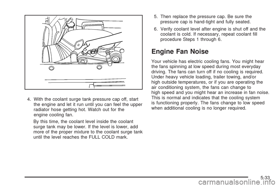
4. With the coolant surge tank pressure cap off, start
the engine and let it run until you can feel the upper
radiator hose getting hot. Watch out for the
engine cooling fan.
By this time, the coolant level inside the coolant
surge tank may be lower. If the level is lower, add
more of the proper mixture to the coolant surge tank
until the level reaches the FULL COLD mark.5. Then replace the pressure cap. Be sure the
pressure cap is hand-tight and fully seated.
6. Verify coolant level after engine is shut off and the
coolant is cold. If necessary, repeat coolant �ll
procedure Steps 1 through 6.
Engine Fan Noise
Your vehicle has electric cooling fans. You might hear
the fans spinning at low speed during most everyday
driving. The fans can turn off if no cooling is required.
Under heavy vehicle loading, trailer towing, and/or
high outside temperatures, or if you are operating the
air conditioning system, the fans can change to
high speed and you might hear an increase in fan noise.
This is normal and indicates that the cooling system
is functioning properly. The fans change to low speed
when additional cooling is no longer required.
5-33