CADILLAC ESCALADE EXT 2010 3.G Owners Manual
Manufacturer: CADILLAC, Model Year: 2010, Model line: ESCALADE EXT, Model: CADILLAC ESCALADE EXT 2010 3.GPages: 580, PDF Size: 6.23 MB
Page 461 of 580
All-Wheel Drive
Transfer Case
If your vehicle is equipped with All-Wheel Drive, be sure
to perform the lubricant checks described in this
section. There are two additional systems that need
lubrication.
When to Check Lubricant
Refer to the Maintenance Schedule to determine
how often to check the lubricant. SeeScheduled
Maintenance on page 8‑3.
How to Check Lubricant
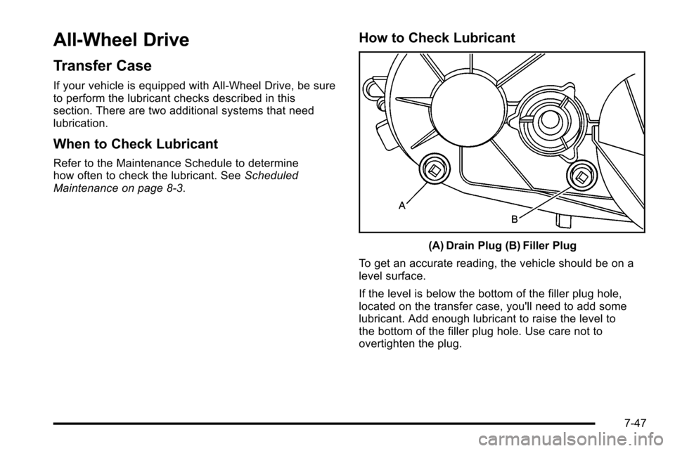
(A) Drain Plug (B) Filler Plug
To get an accurate reading, the vehicle should be on a
level surface.
If the level is below the bottom of the filler plug hole,
located on the transfer case, you'll need to add some
lubricant. Add enough lubricant to raise the level to
the bottom of the filler plug hole. Use care not to
overtighten the plug.
7-47
Page 462 of 580
What to Use
Refer to the Maintenance Schedule to determine what
kind of lubricant to use. SeeRecommended Fluids and
Lubricants on page 8‑10.
Rear Axle
When to Check Lubricant
It is not necessary to regularly check rear axle fluid
unless you suspect there is a leak or you hear an
unusual noise. A fluid loss could indicate a problem.
Have it inspected and repaired.
All axle assemblies are filled by volume of fluid during
production. They are not filled to reach a certain level.
When checking the fluid level on any axle, variations in
the readings can be caused by factory fill differences
between the minimum and the maximum fluid volume.
Also, if a vehicle has just been driven before checking
the fluid level, it may appear lower than normal because
fluid has traveled out along the axle tubes and has not
drained back to the sump area. Therefore, a reading
taken five minutes after the vehicle has been driven will
appear to have a lower fluid level than a vehicle that
has been stationary for an hour or two. Remember that
the rear axle assembly must be supported to get a true
reading.
How to Check Lubricant
To get an accurate reading, the vehicle should be on a
level surface.
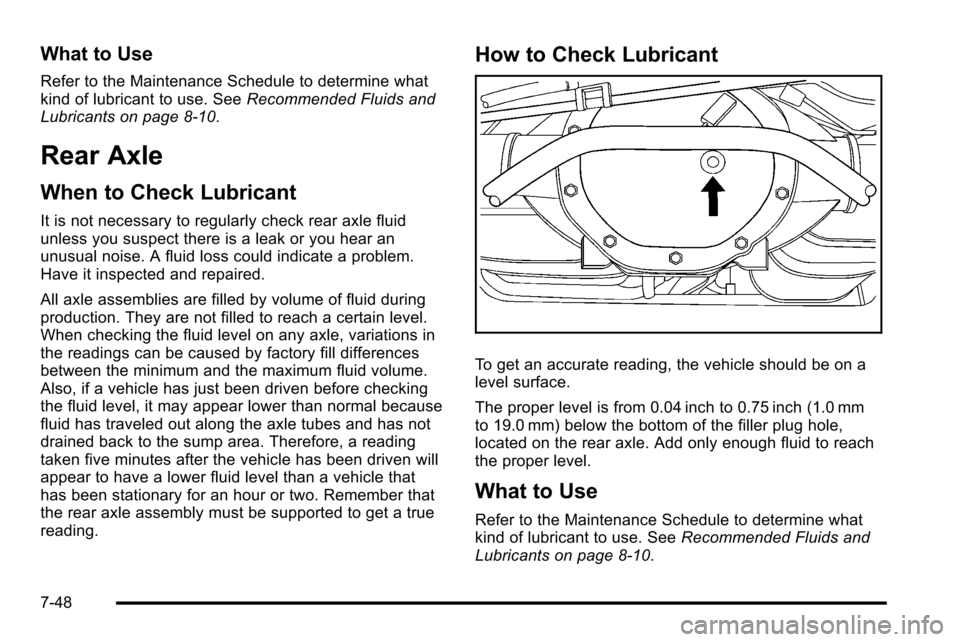
The proper level is from 0.04 inch to 0.75 inch (1.0 mm
to 19.0 mm) below the bottom of the filler plug hole,
located on the rear axle. Add only enough fluid to reach
the proper level.
What to Use
Refer to the Maintenance Schedule to determine what
kind of lubricant to use. See Recommended Fluids and
Lubricants on page 8‑10.
7-48
Page 463 of 580

Front Axle
When to Check and Change Lubricant
It is not necessary to regularly check front axle fluid
unless you suspect there is a leak or you hear an
unusual noise. A fluid loss could indicate a problem.
Have it inspected and repaired.
How to Check Lubricant
To get an accurate reading, the vehicle should be on a
level surface.
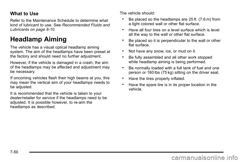
A :Fill Plug
B : Drain Plug
.When the differential is cold, add enough lubricant
to raise the level from 0 (0 mm) to 1/8 inch
(3.2 mm) below the filler plug hole.
.When the differential is at operating temperature
(warm), add enough lubricant to raise the level to
the bottom of the filler plug hole.
7-49
Page 464 of 580
What to Use
Refer to the Maintenance Schedule to determine what
kind of lubricant to use. SeeRecommended Fluids and
Lubricants on page 8‑10.
Headlamp Aiming
The vehicle has a visual optical headlamp aiming
system. The aim of the headlamps have been preset at
the factory and should need no further adjustment.
However, if the vehicle is damaged in a crash, the aim
of the headlamps may be affected and adjustment may
be necessary.
If oncoming vehicles flash their high beams at you, this
may mean the vertical aim of your headlamps needs to
be adjusted.
It is recommended that the vehicle is taken to your
dealer/retailer for service if the headlamps need to be
adjusted. It is possible however, to re-aim the
headlamps as described. The vehicle should:
.Be placed so the headlamps are 25 ft. (7.6 m) from
a light colored wall or other flat surface.
.Have all four tires on a level surface which is level
all the way to the wall or other flat surface.
.Be placed so it is perpendicular to the wall or other
flat surface.
.Not have any snow, ice, or mud on it.
.Be fully assembled and all other work stopped
while headlamp aiming is being performed.
.Be normally loaded with a full tank of fuel and one
person or 160 lbs (75 kg) sitting on the driver seat.
.Have the tires properly inflated.
.Have the spare tire is in its proper location in the
vehicle.
7-50
Page 465 of 580
Headlamp aiming is done with the vehicle's low-beam
headlamps. The high-beam headlamps will be correctly
aimed if the low-beam headlamps are aimed properly.
To adjust the vertical aim:1. Open the hood. See Hood Release
on page 7‑13for more information.
2. Locate the center of
the projector lens of
the low‐beam
headlamp.
3. Record the distance from the ground to the center of the projector lens of the low‐beam headlamp.
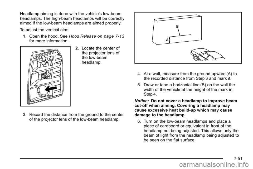
4. At a wall, measure from the ground upward (A) tothe recorded distance from Step 3 and mark it.
5. Draw or tape a horizontal line (B) on the wall the width of the vehicle at the height of the mark in
Step 4.
Notice: Do not cover a headlamp to improve beam
cut-off when aiming. Covering a headlamp may
cause excessive heat build-up which may cause
damage to the headlamp.
6. Turn on the low-beam headlamps and place a piece of cardboard or equivalent in front of the
headlamp not being adjusted. This allows only the
beam of light from the headlamp being adjusted to
be seen on the flat surface.
7-51
Page 466 of 580

7. Locate the vertical headlamp aiming screws, whichare under the hood near each headlamp assembly.
The adjustment screw can be turned with a
E8 Torx
®socket.
8. Turn the vertical aiming screw until the headlamp beam is aimed to the horizontal tape line. Turn it
clockwise or counterclockwise to raise or lower the
angle of the beam.
9. Make sure that the light from the headlamp is
positioned at the bottom edge of the horizontal
tape line. The lamp on the left (A) shows the
correct headlamp aim. The lamp on the right (B)
shows the incorrect headlamp aim.
10. Repeat Steps 7 through 9 for the opposite headlamp.
7-52
Page 467 of 580

Bulb Replacement
For the proper type of replacement bulbs, see
Replacement Bulbs on page 7‑55.
For any bulb changing procedure not listed in this
section, contact your dealer/retailer.
High Intensity Discharge (HID)
Lighting
{WARNING:
The low beam high intensity discharge lighting
system operates at a very high voltage. If you try
to service any of the system components, you
could be seriously injured. Have your dealer/
retailer or a qualified technician service them.
The vehicle may have HID headlamps. After an HID
headlamp bulb has been replaced, you may notice that
the beam is a slightly different shade than it was
originally. This is normal.
Taillamps, Turn Signal, Sidemarker,
Stoplamps and Back-up Lamps
To replace one of these bulbs:
A. Stoplamp/Turn Signal/Taillamp
B. Stoplamp/Turn Signal/Taillamp
C. Back-up Lamp
D. Sidemarker Lamp
1. Open the tailgate. See Tailgate
on page 3‑21for
more information.
7-53
Page 468 of 580

2. Remove the twoscrews from the
taillamp assembly. 3. Pull the taillamp assembly straight back to remove.
4. Turn the bulb socket counterclockwise to remove it
from the taillamp assembly.
5. Pull the bulb straight out from the socket.
6. Press a new bulb into the socket, insert it into the taillamp assembly and turn the bulb socket
clockwise until it clicks.
7. Reinstall the taillamp assembly and tighten the screws.
7-54
Page 469 of 580
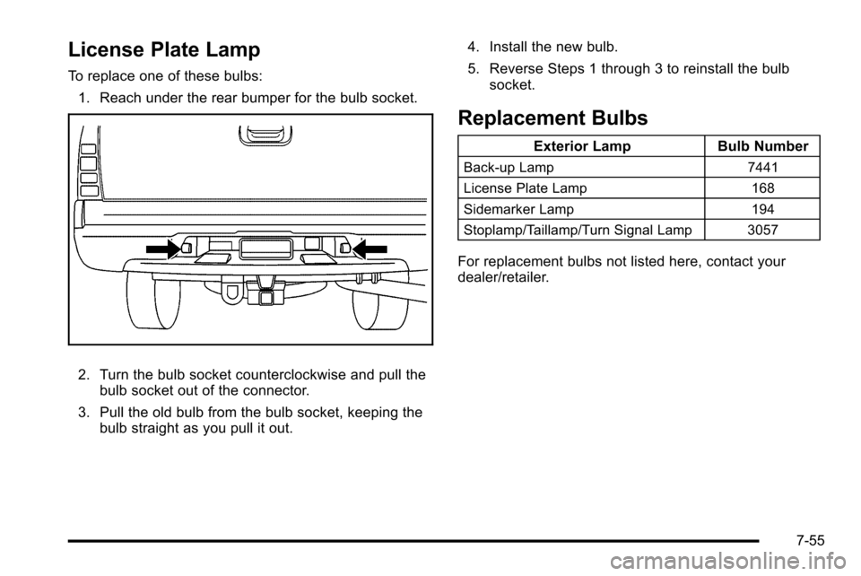
License Plate Lamp
To replace one of these bulbs:1. Reach under the rear bumper for the bulb socket.
2. Turn the bulb socket counterclockwise and pull the bulb socket out of the connector.
3. Pull the old bulb from the bulb socket, keeping the bulb straight as you pull it out. 4. Install the new bulb.
5. Reverse Steps 1 through 3 to reinstall the bulb
socket.
Replacement Bulbs
Exterior Lamp Bulb Number
Back-up Lamp 7441
License Plate Lamp 168
Sidemarker Lamp 194
Stoplamp/Taillamp/Turn Signal Lamp 3057
For replacement bulbs not listed here, contact your
dealer/retailer.
7-55
Page 470 of 580
Windshield Wiper Blade
Replacement
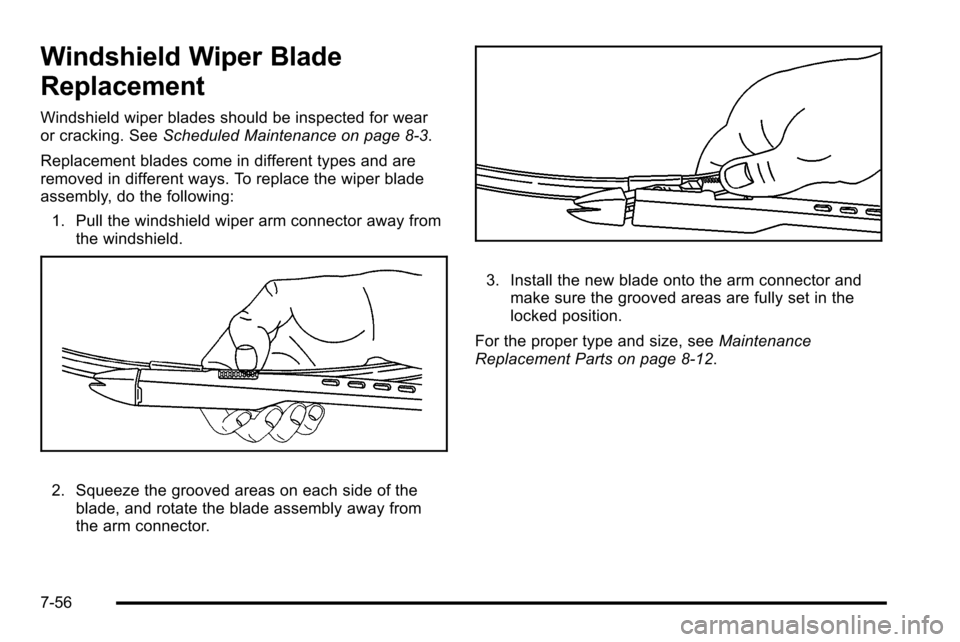
Windshield wiper blades should be inspected for wear
or cracking. SeeScheduled Maintenance on page 8‑3.
Replacement blades come in different types and are
removed in different ways. To replace the wiper blade
assembly, do the following: 1. Pull the windshield wiper arm connector away from the windshield.
2. Squeeze the grooved areas on each side of the
blade, and rotate the blade assembly away from
the arm connector.
3. Install the new blade onto the arm connector andmake sure the grooved areas are fully set in the
locked position.
For the proper type and size, see Maintenance
Replacement Parts on page 8‑12.
7-56