driver seat adjustment CADILLAC SEVILLE 2004 5.G Owners Manual
[x] Cancel search | Manufacturer: CADILLAC, Model Year: 2004, Model line: SEVILLE, Model: CADILLAC SEVILLE 2004 5.GPages: 410, PDF Size: 2.64 MB
Page 99 of 410

Outside Curb View Assist Mirror
If your vehicle is equipped with memory mirrors, it will
also be capable of performing the curb view assist mirror
feature. This feature will allow the passenger’s side
mirror to tilt to a factory programmed position when the
vehicle is in REVERSE (R). This feature may be
useful in allowing you to view the curb when you are
parallel parking.
When the vehicle is shifted out of REVERSE (R) and a
five-second delay has occurred, the passenger’s
side mirror will return to its original position.
If further adjustment is needed after the mirror is tilted,
the mirror switch may be used.
This feature can be enabled/disabled through the Driver
Information Center (DIC). SeeDIC Vehicle
Personalization on page 3-63for more information.
Outside Convex Mirror
Your passenger’s side mirror is convex. A convex mirror’s
surface is curved so you can see more from the driver’s
seat. This mirror does not have a dimming feature.
{CAUTION:
A convex mirror can make things (like other
vehicles) look farther away than they really are.
If you cut too sharply into the right lane, you
could hit a vehicle on your right. Check your
inside mirror or glance over your shoulder
before changing lanes.
Outside Heated Mirrors
When you operate the rear window defogger, it also
warms both outside mirrors to help clear them of fog or
ice. SeeDual Climate Control System on page 3-28
for more information.
2-41
Page 117 of 410

The main components of the instrument panel are the
following:
A. Air Outlets. SeeOutlet Adjustment on page 3-33.
B. Driver Information Center (DIC) Buttons. See
DIC Controls and Displays on page 3-52.
C. Turn Signal/Multifunction Lever. SeeTurn
Signal/Multifunction Lever on page 3-9.
D. Climate Controls and OnStar
®Steering Wheel
Controls (or Cellular Telephone Controls, If
Equipped). SeeSteering Wheel Climate Controls on
page 3-36andOnStar
®System on page 2-42.
E. Instrument Panel Cluster. SeeInstrument Panel
Cluster on page 3-38.
F. Windshield Wiper/Washer Lever. See “Windshield
Wipers” underTurn Signal/Multifunction Lever
on page 3-9.
G. Audio Steering Wheel Controls. SeeAudio Steering
Wheel Controls on page 3-100.
H. Ignition Switch. SeeIgnition Positions on page 2-25.
I. Air Outlet Thumbwheel. SeeOutlet Adjustment
on page 3-33.
J. Hazard Warning Flasher Button. SeeHazard
Warning Flashers on page 3-6.K. Audio System. SeeAudio System(s) on page 3-75.
L. Exterior Lamp Controls. SeeExterior Lamps on
page 3-16.
M. Hood Release. SeeHood Release on page 5-11.
N. Fuel Door Release. SeeFilling Your Tank on
page 5-7.
O. Trunk Release Button. SeeTrunk on page 2-13.
P. Cruise Control. See “Cruise Control” under
Turn Signal/Multifunction Lever on page 3-9.
Q. Horn. SeeHorn on page 3-7.
R. Heated Seat Controls. SeeHeated Seats on
page 1-3.
S. Traction Control System (TCS) Button. SeeTraction
Control System (TCS) on page 4-8.
T. Console Shift Lever. SeeAutomatic Transaxle
Operation on page 2-28.
U. Optional Ashtray. SeeAshtrays and Cigarette
Lighter on page 3-27.
V. Climate Controls. SeeDual Climate Control System
on page 3-28.
W. Glove Box. SeeGlove Box on page 2-49.
3-5
Page 310 of 410

The vehicle should be properly prepared as follows:
•The vehicle should be placed so the headlamps are
25 ft. (7.6 m) from a light colored wall or other flat
surface.
•The vehicle must have all four tires on a perfectly
level surface which is level all the way to the wall
or other flat surface.
•The vehicle should be placed so it is perpendicular
to the wall or other flat surface.
•The vehicle should not have any snow, ice or mud
attached to it.
•The vehicle should be fully assembled and all other
work stopped while headlamp aiming is being done.
•The vehicle should be normally loaded with a
full tank of fuel and one person or 160 lbs (75 kg) on
the driver’s seat.
•Tires should be properly inflated.
•Start the vehicle and rock it to level the suspension.
Headlamp aiming is done with the vehicle low beam
lamps. The high beam lamps will be correctly aimed if
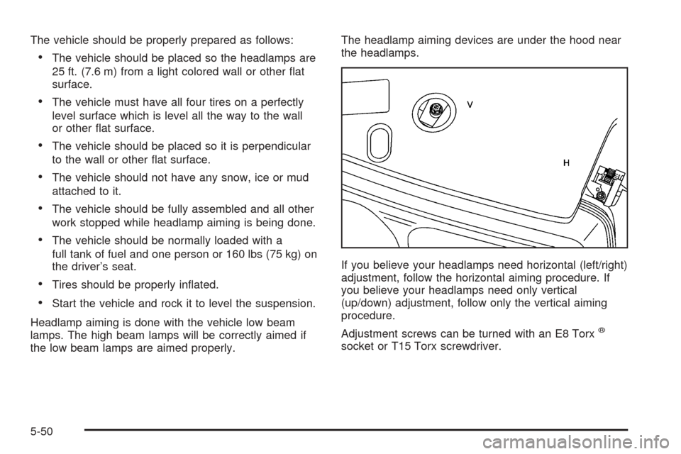
the low beam lamps are aimed properly.The headlamp aiming devices are under the hood near
the headlamps.
If you believe your headlamps need horizontal (left/right)
adjustment, follow the horizontal aiming procedure. If
you believe your headlamps need only vertical
(up/down) adjustment, follow only the vertical aiming
procedure.
Adjustment screws can be turned with an E8 Torx
®
socket or T15 Torx screwdriver.
5-50