service CADILLAC STS 2008 1.G Manual Online
[x] Cancel search | Manufacturer: CADILLAC, Model Year: 2008, Model line: STS, Model: CADILLAC STS 2008 1.GPages: 500, PDF Size: 5.81 MB
Page 388 of 500
The Tire Pressure Monitor System (TPMS) operates on
a radio frequency and complies with RSS-210 of
Industry and Science Canada. Operation is subject to
the following two conditions:
1. This device may not cause interference.
2. This device must accept any interference received,
including interference that may cause undesired
operation of the device.
Changes or modi�cations to this system by other than
an authorized service facility could void authorization to
use this equipment.
Tire Pressure Monitor Operation
The Tire Pressure Monitor System (TPMS) is designed
to warn the driver when a low tire pressure condition
exists. TPMS sensors are mounted onto each tire
and wheel assembly, excluding the spare tire and wheel
assembly. The TPMS sensors monitor the air pressure
in the vehicle’s tires and transmits the tire pressure
readings to a receiver located in the vehicle.When a low tire pressure
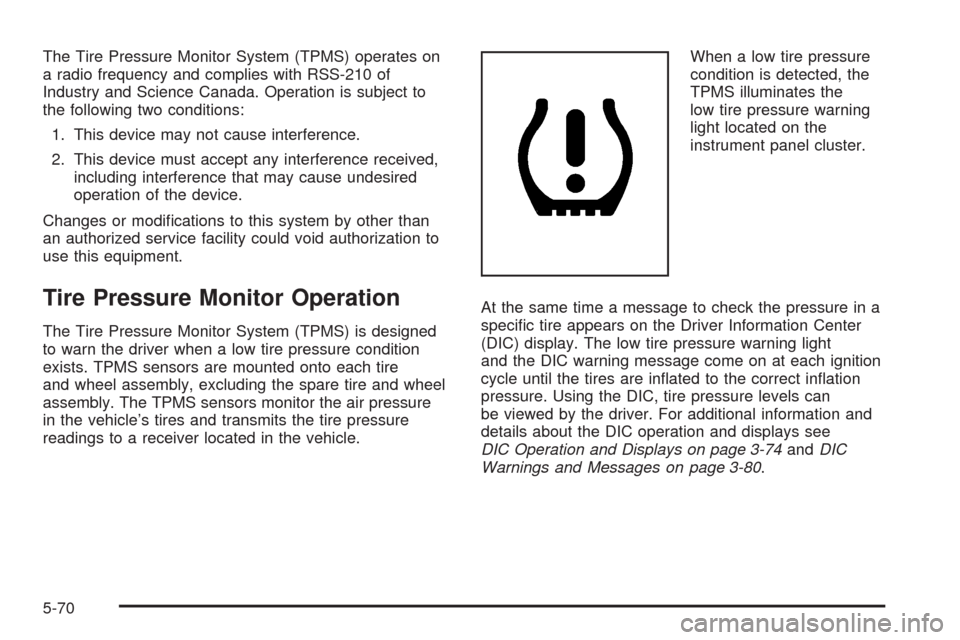
condition is detected, the
TPMS illuminates the
low tire pressure warning
light located on the
instrument panel cluster.
At the same time a message to check the pressure in a
speci�c tire appears on the Driver Information Center
(DIC) display. The low tire pressure warning light
and the DIC warning message come on at each ignition
cycle until the tires are in�ated to the correct in�ation
pressure. Using the DIC, tire pressure levels can
be viewed by the driver. For additional information and
details about the DIC operation and displays see
DIC Operation and Displays on page 3-74andDIC
Warnings and Messages on page 3-80.
5-70
Page 390 of 500
One or more TPMS sensors are missing or
damaged. The DIC message and the TPMS
malfunction light should go off when the TPMS
sensors are installed and the sensor matching
process is performed successfully. See your
dealer/retailer for service.
Replacement tires or wheels do not match your
vehicle’s original equipment tires or wheels.
Tires and wheels other than those recommended
for your vehicle could prevent the TPMS from
functioning properly. SeeBuying New Tires on
page 5-76.
Operating electronic devices or being near facilities
using radio wave frequencies similar to the TPMS
could cause the TPMS sensors to malfunction.
If the TPMS is not functioning it cannot detect or signal
a low tire condition. See your dealer/retailer for
service if the TPMS malfunction light and DIC message
comes on and stays on.
TPMS Sensor Matching Process
Each TPMS sensor has a unique identi�cation code.
Any time you replace one or more of the TPMS sensors
or rotate your vehicle’s tires, the identi�cation codes
will need to be matched to the new tire/wheel position.The sensors are matched to the tire/wheel positions in
the following order: driver side front tire, passenger
side front tire, passenger side rear tire, and driver side
rear tire using a TPMS diagnostic tool. See your
dealer/retailer for service.
The TPMS sensors may also be matched to each
tire/wheel position by increasing or decreasing the tire’s
air pressure. When increasing the tire’s pressure, do
not exceed the maximum in�ation pressure indicated on
the tire’s sidewall. If using this method to match
TPMS sensors, the complete procedure outlined below
must be performed within 15 minutes of the vehicle
being stationary.
To decrease air-pressure out of a tire you can use the
pointed end of the valve cap, a pencil-style air pressure
gage, or a key.
You will have one minute to match the �rst tire/wheel
position, and �ve minutes overall, to match all four
tire/wheel positions. If it takes longer than one minute to
match the �rst tire and wheel, or more than �ve
minutes to match all four tire/wheel positions, the
matching process stops and you will need to start over.
5-72
Page 397 of 500
Uniform Tire Quality Grading
Quality grades can be found where applicable on
the tire sidewall between tread shoulder and
maximum section width. For example:
Treadwear 200 Traction AA Temperature A
The following information relates to the system
developed by the United States National Highway
Traffic Safety Administration (NHTSA), which
grades tires by treadwear, traction, and
temperature performance. This applies only to
vehicles sold in the United States. The grades are
molded on the sidewalls of most passenger car
tires. The Uniform Tire Quality Grading (UTQG)
system does not apply to deep tread, winter-type
snow tires, space-saver, or temporary use
spare tires, tires with nominal rim diameters of
10 to 12 inches (25 to 30 cm), or to some
limited-production tires.
While the tires available on General Motors
passenger cars and light trucks may vary with
respect to these grades, they must also conform
to federal safety requirements and additional
General Motors Tire Performance Criteria (TPC)
standards.
Treadwear
The treadwear grade is a comparative rating
based on the wear rate of the tire when tested
under controlled conditions on a speci�ed
government test course. For example, a tire
graded 150 would wear one and a half (1.5) times
as well on the government course as a tire
graded 100. The relative performance of tires
depends upon the actual conditions of their use,
however, and may depart signi�cantly from
the norm due to variations in driving habits, service
practices, and differences in road characteristics
and climate.
Traction – AA, A, B, C
The traction grades, from highest to lowest, are
AA, A, B, and C. Those grades represent the tire’s
ability to stop on wet pavement as measured
under controlled conditions on speci�ed
government test surfaces of asphalt and concrete.
A tire marked C may have poor traction
performance.
Warning
:The traction grade assigned to
this tire is based on straight-ahead braking
traction tests, and does not include
acceleration, cornering, hydroplaning,
or peak traction characteristics.
5-79
Page 403 of 500
Lifting From the Front
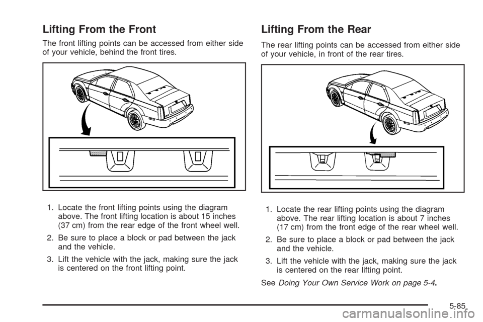
The front lifting points can be accessed from either side
of your vehicle, behind the front tires.
1. Locate the front lifting points using the diagram
above. The front lifting location is about 15 inches
(37 cm) from the rear edge of the front wheel well.
2. Be sure to place a block or pad between the jack
and the vehicle.
3. Lift the vehicle with the jack, making sure the jack
is centered on the front lifting point.
Lifting From the Rear
The rear lifting points can be accessed from either side
of your vehicle, in front of the rear tires.
1. Locate the rear lifting points using the diagram
above. The rear lifting location is about 7 inches
(17 cm) from the front edge of the rear wheel well.
2. Be sure to place a block or pad between the jack
and the vehicle.
3. Lift the vehicle with the jack, making sure the jack
is centered on the rear lifting point.
SeeDoing Your Own Service Work on page 5-4.
5-85
Page 405 of 500
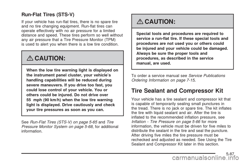
Run-Flat Tires (STS-V)
If your vehicle has run-�at tires, there is no spare tire
and no tire changing equipment. Run-�at tires can
operate effectively with no air pressure for a limited
distance and speed. These tires perform so well without
any air pressure that a Tire Pressure Monitor (TPM)
is used to alert you when there is a low tire condition.
{CAUTION:
When the low tire warning light is displayed on
the instrument panel cluster, your vehicle’s
handling capabilities will be reduced during
severe maneuvers. If you drive too fast, you
could lose control of your vehicle. You or
others could be injured. Do not drive over
55 mph (90 km/h) when the low tire warning
light is displayed. Drive cautiously and check
your tire pressures as soon as you can.
SeeRun-Flat Tires (STS-V) on page 5-65andTire
Pressure Monitor System on page 5-68, for additional
information.
{CAUTION:
Special tools and procedures are required to
service a run-�at tire. If these special tools and
procedures are not used you or others could
be injured and your vehicle could be damaged.
Always be sure the proper tools and
procedures, as described in the service
manual, are used.
To order a service manual seeService Publications
Ordering Information on page 7-15.
Tire Sealant and Compressor Kit
Your vehicle has a tire sealant and compressor kit that
is capable of temporarily sealing small punctures in
the tread. There is no jack or spare tire. The kit in�ates
the tire with liquid sealant and air. After the tire is
in�ated to the recommended in�ation pressure, see
Inflation - Tire Pressure on page 5-66for more
information, the vehicle must be driven for �ve miles to
distribute the sealant in the tire and seal the puncture.
After driving �ve miles the tire pressure must be
rechecked and adjusted as needed. See Using the Tire
Sealant and Compressor Kit later in this section.
5-87
Page 407 of 500
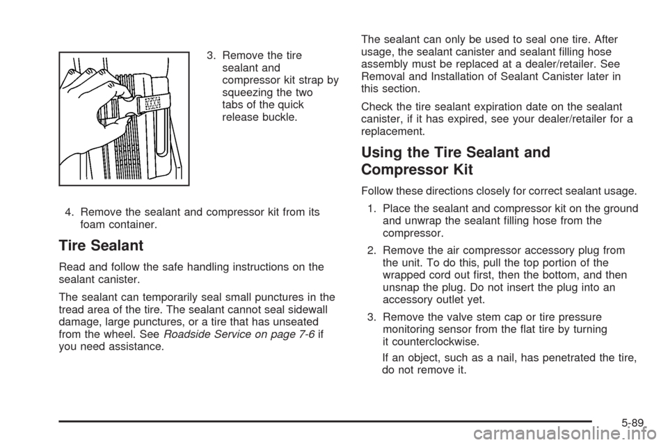
3. Remove the tire
sealant and
compressor kit strap by
squeezing the two
tabs of the quick
release buckle.
4. Remove the sealant and compressor kit from its
foam container.
Tire Sealant
Read and follow the safe handling instructions on the
sealant canister.
The sealant can temporarily seal small punctures in the
tread area of the tire. The sealant cannot seal sidewall
damage, large punctures, or a tire that has unseated
from the wheel. SeeRoadside Service on page 7-6if
you need assistance.The sealant can only be used to seal one tire. After
usage, the sealant canister and sealant �lling hose
assembly must be replaced at a dealer/retailer. See
Removal and Installation of Sealant Canister later in
this section.
Check the tire sealant expiration date on the sealant
canister, if it has expired, see your dealer/retailer for a
replacement.
Using the Tire Sealant and
Compressor Kit
Follow these directions closely for correct sealant usage.
1. Place the sealant and compressor kit on the ground
and unwrap the sealant �lling hose from the
compressor.
2. Remove the air compressor accessory plug from
the unit. To do this, pull the top portion of the
wrapped cord out �rst, then the bottom, and then
unsnap the plug. Do not insert the plug into an
accessory outlet yet.
3. Remove the valve stem cap or tire pressure
monitoring sensor from the �at tire by turning
it counterclockwise.
If an object, such as a nail, has penetrated the tire,
do not remove it.
5-89
Page 409 of 500
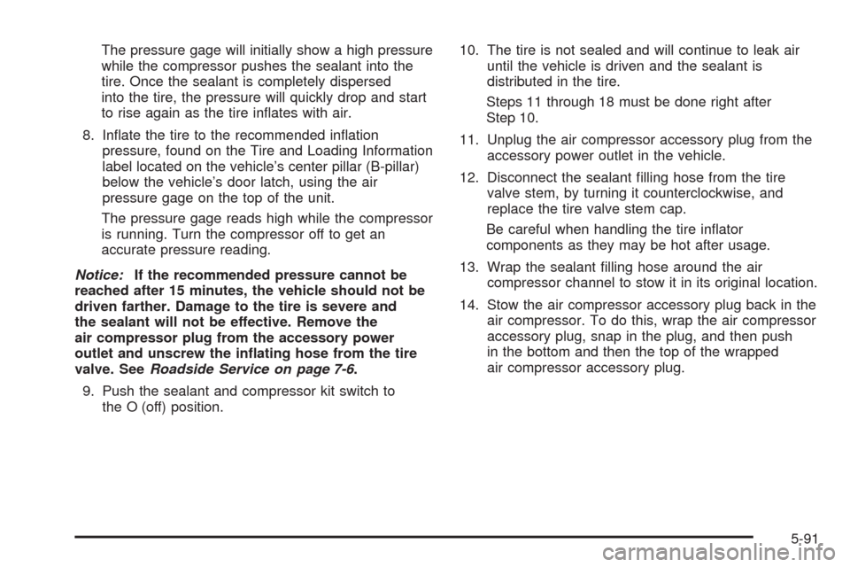
The pressure gage will initially show a high pressure
while the compressor pushes the sealant into the
tire. Once the sealant is completely dispersed
into the tire, the pressure will quickly drop and start
to rise again as the tire in�ates with air.
8. In�ate the tire to the recommended in�ation
pressure, found on the Tire and Loading Information
label located on the vehicle’s center pillar (B-pillar)
below the vehicle’s door latch, using the air
pressure gage on the top of the unit.
The pressure gage reads high while the compressor
is running. Turn the compressor off to get an
accurate pressure reading.
Notice:If the recommended pressure cannot be
reached after 15 minutes, the vehicle should not be
driven farther. Damage to the tire is severe and
the sealant will not be effective. Remove the
air compressor plug from the accessory power
outlet and unscrew the in�ating hose from the tire
valve. SeeRoadside Service on page 7-6.
9. Push the sealant and compressor kit switch to
the O (off) position.10. The tire is not sealed and will continue to leak air
until the vehicle is driven and the sealant is
distributed in the tire.
Steps 11 through 18 must be done right after
Step 10.
11. Unplug the air compressor accessory plug from the
accessory power outlet in the vehicle.
12. Disconnect the sealant �lling hose from the tire
valve stem, by turning it counterclockwise, and
replace the tire valve stem cap.
Be careful when handling the tire in�ator
components as they may be hot after usage.
13. Wrap the sealant �lling hose around the air
compressor channel to stow it in its original location.
14. Stow the air compressor accessory plug back in the
air compressor. To do this, wrap the air compressor
accessory plug, snap in the plug, and then push
in the bottom and then the top of the wrapped
air compressor accessory plug.
5-91
Page 411 of 500
18. If the tire pressure has fallen more then 10 psi
(68 kPa), below the recommended in�ation
pressure, stop driving the vehicle. The tire is too
severely damaged and the tire sealant and
compressor kit cannot seal the tire. SeeRoadside
Service on page 7-6for more information.
If the tire pressure has not dropped more than
10 psi (68 kPa) from the recommended in�ation
pressure, you can in�ate the tire back up to
the recommended in�ation pressure.
19. Wipe off any sealant from the wheel, tire, and
vehicle with a rag.
20. Dispose of the sealant canister at a local
dealer/retailer or in accordance with your local state
codes and practices.
After using the sealant canister, replace it with a
new canister from your dealer/retailer.
21. After temporarily sealing a tire with the tire sealant
and compressor kit, take your vehicle to your
dealer/retailer to have the tire inspected and
repaired.Using the Air Compressor without
Sealant
To use the air compressor to in�ate a tire with air only
and not sealant:
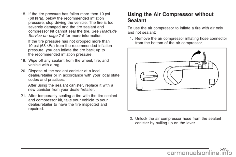
1. Remove the air compressor in�ating hose connector
from the bottom of the air compressor.
2. Unlock the air compressor hose from the sealant
canister by pulling up on the lever.
5-93
Page 434 of 500
Vehicle Identi�cation
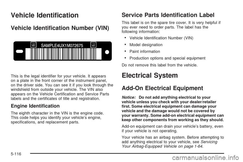
Vehicle Identi�cation Number (VIN)
This is the legal identi�er for your vehicle. It appears
on a plate in the front corner of the instrument panel,
on the driver side. You can see it if you look through the
windshield from outside your vehicle. The VIN also
appears on the Vehicle Certi�cation and Service Parts
labels and the certi�cates of title and registration.
Engine Identi�cation
The eighth character in the VIN is the engine code.
This code helps you identify your vehicle’s engine,
speci�cations, and replacement parts.
Service Parts Identi�cation Label
This label is on the spare tire cover. It is very helpful if
you ever need to order parts. The label has the
following information:
Vehicle Identi�cation Number (VIN)
Model designation
Paint information
Production options and special equipment
Do not remove this label from the vehicle.
Electrical System
Add-On Electrical Equipment
Notice:Do not add anything electrical to your
vehicle unless you check with your dealer/retailer
�rst. Some electrical equipment can damage your
vehicle and the damage would not be covered by
your warranty. Some add-on electrical equipment can
keep other components from working as they should.
Add-on equipment can drain your vehicle’s battery, even
if your vehicle is not operating.
Your vehicle has an airbag system. Before attempting to
add anything electrical to your vehicle, seeServicing
Your Airbag-Equipped Vehicle on page 1-64.
5-116
Page 449 of 500
Maintenance Schedule......................................6-2
Introduction...................................................6-2
Maintenance Requirements..............................6-2
Your Vehicle and the Environment....................6-2
Using the Maintenance Schedule......................6-3
Scheduled Maintenance...................................6-4
Additional Required Services............................6-6
Maintenance Footnotes...................................6-8Owner Checks and Services............................6-9
At Each Fuel Fill............................................6-9
At Least Once a Month.................................6-10
At Least Once a Year...................................6-11
Recommended Fluids and Lubricants...............6-13
Normal Maintenance Replacement Parts..........6-15
Engine Drive Belt Routing..............................6-16
Maintenance Record.....................................6-18
Section 6 Maintenance Schedule
6-1