remote start CADILLAC XLR V 2007 1.G Owners Manual
[x] Cancel search | Manufacturer: CADILLAC, Model Year: 2007, Model line: XLR V, Model: CADILLAC XLR V 2007 1.GPages: 512, PDF Size: 3.84 MB
Page 1 of 512
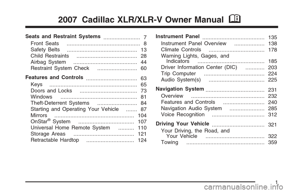
Seats and Restraint Systems
....................... 7
Front Seats
.............................................. 8
Safety Belts
............................................ 13
Child Restraints
...................................... 28
Airbag System
........................................ 44
Restraint System Check
......................... 60
Features and Controls
................................ 63
Keys
....................................................... 65
Doors and Locks
.................................... 73
Windows
................................................ 81
Theft-Deterrent Systems
......................... 84
Starting and Operating Your Vehicle
....... 87
Mirrors
.................................................. 104
OnStar
®System
................................... 107
Universal Home Remote System
.......... 110
Storage Areas
...................................... 121
Retractable Hardtop
.............................. 124Instrument Panel
....................................... 135
Instrument Panel Overview
................... 138
Climate Controls
................................... 178
Warning Lights, Gages, and
Indicators
.......................................... 185
Driver Information Center (DIC)
............ 203
Trip Computer
...................................... 224
Audio System(s)
................................... 225
Navigation System
..................................... 231
Overview
.............................................. 232
Features and Controls
.......................... 240
Navigation Audio System
...................... 285
Voice Recognition
................................. 312
Driving Your Vehicle
................................. 321
Your Driving, the Road, and
Your Vehicle
..................................... 322
Towing
................................................. 359
2007 Cadillac XLR/XLR-V Owner ManualM
1
Page 63 of 512
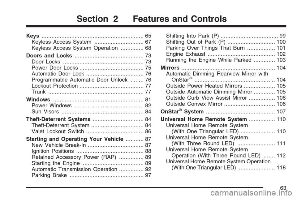
Keys.............................................................. 65
Keyless Access System.............................. 67
Keyless Access System Operation.............. 68
Doors and Locks.......................................... 73
Door Locks................................................. 73
Power Door Locks....................................... 75
Automatic Door Lock................................... 76
Programmable Automatic Door Unlock........ 76
Lockout Protection....................................... 77
Trunk.......................................................... 77
Windows....................................................... 81
Power Windows.......................................... 82
Sun Visors.................................................. 84
Theft-Deterrent Systems............................... 84
Theft-Deterrent System................................ 84
Valet Lockout Switch................................... 86
Starting and Operating Your Vehicle........... 87
New Vehicle Break-In.................................. 87
Ignition Positions......................................... 88
Retained Accessory Power (RAP)............... 89
Starting the Engine..................................... 89
Automatic Transmission Operation............... 92
Parking Brake............................................. 97Shifting Into Park (P)................................... 99
Shifting Out of Park (P)............................. 100
Parking Over Things That Burn................. 101
Engine Exhaust......................................... 102
Running the Engine While Parked............. 103
Mirrors......................................................... 104
Automatic Dimming Rearview Mirror with
OnStar
®................................................. 104
Outside Power Heated Mirrors................... 105
Outside Automatic Dimming Mirror............. 105
Outside Curb View Assist Mirror................ 106
Outside Convex Mirror............................... 106
OnStar
®System.......................................... 107
Universal Home Remote System................ 110
Universal Home Remote System
(With One Triangular LED)..................... 110
Universal Home Remote System
(With Three Round LED)....................... 111
Universal Home Remote System
Operation (With Three Round LED)....... 112
Universal Home Remote System Operation
(With One Triangular LED)...................... 118
Section 2 Features and Controls
63
Page 120 of 512
6. Locate in the garage, the garage door opener
receiver (motor-head unit). Locate the “Learn”
or “Smart” button. This can usually be
found where the hanging antenna wire is
attached to the motor-head unit.
7. Firmly press and release the “Learn” or
“Smart” button. The name and color of
the button may vary by manufacturer.
You will have 30 seconds to start Step 8.
8. Return to the vehicle. Firmly press and hold
the programmed Universal Home Remote
button for two seconds, then release it.
Immediately press and hold the same button
a second time for two seconds, then
release it. Immediately, press and hold the
same button a third time for two seconds, then
release.
The Universal Home Remote should now
activate your rolling-code equipped device.
To program the remaining two Universal Home
Remote buttons, begin with Step 2 of
“Programming Universal Home Remote.” You do
not want to repeat Step 1, as this will erase
all previous programming from the Universal Home
Remote buttons.Gate Operator and Canadian
Programming
Canadian radio-frequency laws require transmitter
signals to time out or quit after several seconds
of transmission. This may not be long enough
for Universal Home Remote to pick up the signal
during programming. Similarly, some U.S. gate
operators are manufactured to time out in
the same manner.
If you live in Canada, or you are having difficulty
programming a gate operator or garage door
opener by using the “Programming Universal
Home Remote” procedures, regardless of where
you live, replace Step 3 under “Programming
Universal Home Remote” with the following:
Continue to press and hold the Universal Home
Remote button while you press and release every
two seconds (cycle) the hand-held transmitter
button until the frequency signal has been
successfully accepted by the Universal Home
Remote. The Universal Home Remote indicator
light will �ash slowly at �rst and then rapidly.
Proceed with Step 4 under “Programming
Universal Home Remote” to complete.
120
Page 212 of 512
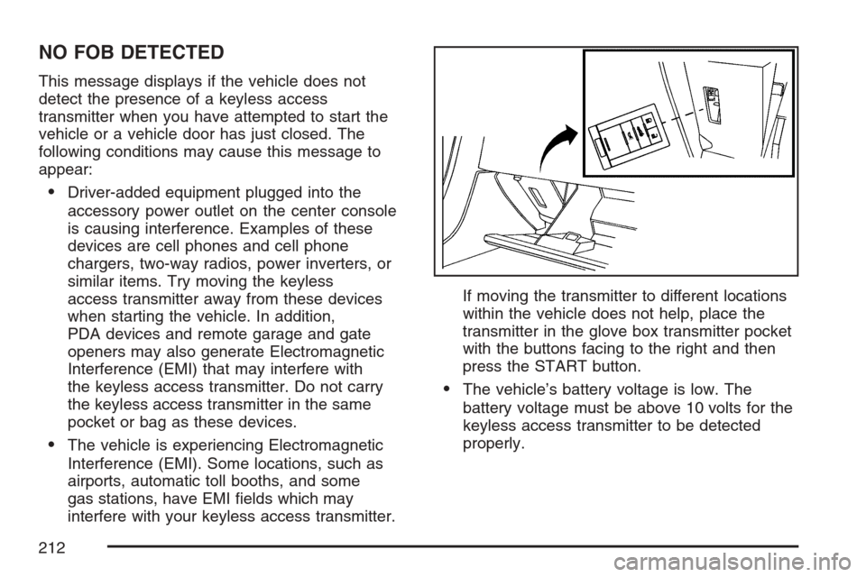
NO FOB DETECTED
This message displays if the vehicle does not
detect the presence of a keyless access
transmitter when you have attempted to start the
vehicle or a vehicle door has just closed. The
following conditions may cause this message to
appear:
Driver-added equipment plugged into the
accessory power outlet on the center console
is causing interference. Examples of these
devices are cell phones and cell phone
chargers, two-way radios, power inverters, or
similar items. Try moving the keyless
access transmitter away from these devices
when starting the vehicle. In addition,
PDA devices and remote garage and gate
openers may also generate Electromagnetic
Interference (EMI) that may interfere with
the keyless access transmitter. Do not carry
the keyless access transmitter in the same
pocket or bag as these devices.
The vehicle is experiencing Electromagnetic
Interference (EMI). Some locations, such as
airports, automatic toll booths, and some
gas stations, have EMI �elds which may
interfere with your keyless access transmitter.If moving the transmitter to different locations
within the vehicle does not help, place the
transmitter in the glove box transmitter pocket
with the buttons facing to the right and then
press the START button.
The vehicle’s battery voltage is low. The
battery voltage must be above 10 volts for the
keyless access transmitter to be detected
properly.
212
Page 406 of 512
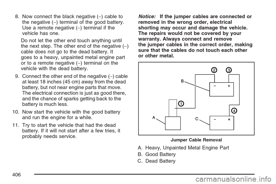
8. Now connect the black negative (−) cable to
the negative (−) terminal of the good battery.
Use a remote negative (−) terminal if the
vehicle has one.
Do not let the other end touch anything until
the next step. The other end of the negative (−)
cable does not go to the dead battery. It
goes to a heavy, unpainted metal engine part
or to a remote negative (−) terminal on the
vehicle with the dead battery.
9. Connect the other end of the negative (−) cable
at least 18 inches (45 cm) away from the dead
battery, but not near engine parts that move.
The electrical connection is just as good there,
and the chance of sparks getting back to the
battery is much less.
10. Now start the vehicle with the good battery
and run the engine for a while.
11. Try to start the vehicle that had the dead
battery. If it will not start after a few tries, it
probably needs service.Notice:If the jumper cables are connected or
removed in the wrong order, electrical
shorting may occur and damage the vehicle.
The repairs would not be covered by your
warranty. Always connect and remove
the jumper cables in the correct order, making
sure that the cables do not touch each other
or other metal.
A. Heavy, Unpainted Metal Engine Part
B. Good Battery
C. Dead Battery
Jumper Cable Removal
406