height CADILLAC XT5 2020 User Guide
[x] Cancel search | Manufacturer: CADILLAC, Model Year: 2020, Model line: XT5, Model: CADILLAC XT5 2020Pages: 384, PDF Size: 6.52 MB
Page 77 of 384

76 SEATS AND RESTRAINTS
{Warning
Children who are up against,
or very close to, any airbag when it
inflates can be seriously injured or
killed. Never put a rear-facing child
restraint in the front outboard seat.
Secure a rear-facing child restraint
in a rear seat. It is also better to
secure a forward-facing child
restraint in a rear seat. If you must
secure a forward-facing child
restraint in the front outboard seat,
always move the front passenger
seat as far back as it will go.
Child restraints are devices used to
restrain, seat, or position children in
the vehicle and are sometimes called
child seats or car seats.
There are three basic types of child
restraints:
.Forward-facing child restraints
. Rear-facing child restraints
. Belt-positioning booster seats
The proper child restraint for your
child depends on their size, weight,
and age, and also on whether the
child restraint is compatible with the
vehicle in which it will be used. For each type of child restraint, there
are many different models available.
When purchasing a child restraint, be
sure it is designed to be used in a
motor vehicle. If it is, the child
restraint will have a label saying that
it meets federal motor vehicle safety
standards.
The instruction manual that is
provided with the child restraint
states the weight and height
limitations for that particular child
restraint. In addition, there are many
kinds of child restraints available for
children with special needs.
{Warning
To reduce the risk of neck and head
injury in a crash, infants and
toddlers should be secured in a
rear-facing child restraint until age
two, or until they reach the
maximum height and weight limits
of their child restraint.
Page 131 of 384
130 INSTRUMENTS AND CONTROLS
Metric
English
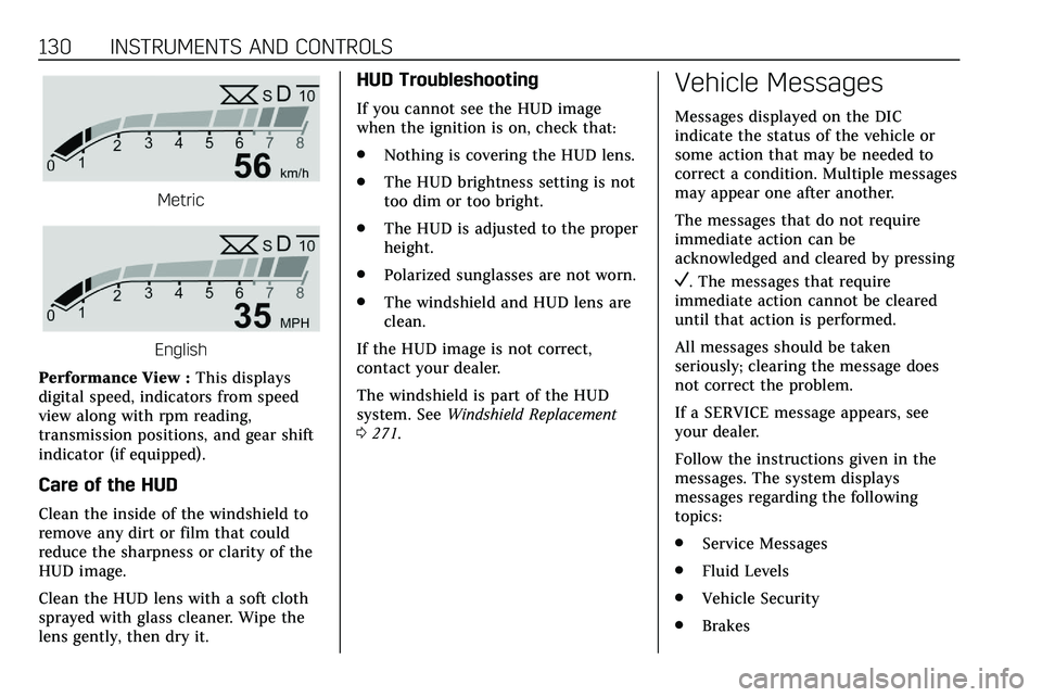
Performance View : This displays
digital speed, indicators from speed
view along with rpm reading,
transmission positions, and gear shift
indicator (if equipped).
Care of the HUD
Clean the inside of the windshield to
remove any dirt or film that could
reduce the sharpness or clarity of the
HUD image.
Clean the HUD lens with a soft cloth
sprayed with glass cleaner. Wipe the
lens gently, then dry it.
HUD Troubleshooting
If you cannot see the HUD image
when the ignition is on, check that:
. Nothing is covering the HUD lens.
. The HUD brightness setting is not
too dim or too bright.
. The HUD is adjusted to the proper
height.
. Polarized sunglasses are not worn.
. The windshield and HUD lens are
clean.
If the HUD image is not correct,
contact your dealer.
The windshield is part of the HUD
system. See Windshield Replacement
0 271.
Vehicle Messages
Messages displayed on the DIC
indicate the status of the vehicle or
some action that may be needed to
correct a condition. Multiple messages
may appear one after another.
The messages that do not require
immediate action can be
acknowledged and cleared by pressing
V. The messages that require
immediate action cannot be cleared
until that action is performed.
All messages should be taken
seriously; clearing the message does
not correct the problem.
If a SERVICE message appears, see
your dealer.
Follow the instructions given in the
messages. The system displays
messages regarding the following
topics:
. Service Messages
. Fluid Levels
. Vehicle Security
. Brakes
Page 227 of 384
226 DRIVING AND OPERATING
still looks blurry, use a soft wet cloth
to gently clean the sensor camera lens
and dry thoroughly. The sensor is
behind the lower front grille below the
driver side headlamp.
The camera must also be aligned to
work correctly. If the camera needs
adjustment, see your dealer. Do not
attempt to adjust the camera yourself.
Side Blind Zone
Alert (SBZA)
If equipped, the SBZA system is a
lane-changing aid that assists drivers
with avoiding crashes that occur with
moving vehicles in the side blind zone
(or spot) areas. When the vehicle is in
a forward gear, the left or right side
mirror display will light up if a moving
vehicle is detected in that blind zone.
If the turn signal is activated and a
vehicle is also detected on the same
side, the display will flash as an extra
warning not to change lanes. Since
this system is part of the Lane Change
Alert (LCA) system, read the entire
LCA section before using this feature.
Lane Change Alert (LCA)
If equipped, the LCA system is a
lane-changing aid that assists drivers
with avoiding lane change crashes
that occur with moving vehicles in the
side blind zone (or spot) areas or with
vehicles rapidly approaching these
areas from behind. The LCA warning
display will light up in the
corresponding outside side mirror and
will flash if the turn signal is on.
{Warning
LCA does not alert the driver to
vehicles outside of the system
detection zones, pedestrians,
bicyclists, or animals. It may not
provide alerts when changing lanes
under all driving conditions. Failure
to use proper care when changing
lanes may result in injury, death,
or vehicle damage. Before making a
lane change, always check mirrors,
glance over your shoulder, and use
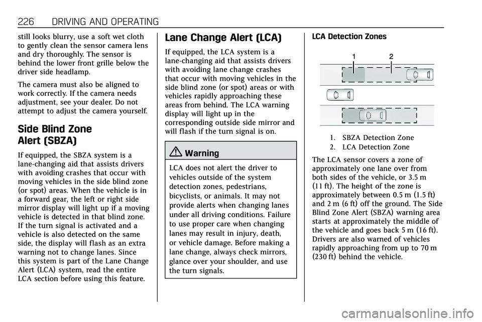
the turn signals.LCA Detection Zones
1. SBZA Detection Zone
2. LCA Detection Zone
The LCA sensor covers a zone of
approximately one lane over from
both sides of the vehicle, or 3.5 m
(11 ft). The height of the zone is
approximately between 0.5 m (1.5 ft)
and 2 m (6 ft) off the ground. The Side
Blind Zone Alert (SBZA) warning area
starts at approximately the middle of
the vehicle and goes back 5 m (16 ft).
Drivers are also warned of vehicles
rapidly approaching from up to 70 m
(230 ft) behind the vehicle.
Page 243 of 384

242 DRIVING AND OPERATING
Hitch Cover
To remove hitch cover, if equipped:1. Remove the two fasteners on the lower tabs.
2. Pull the lower edge of the cover to about a 45 degree angle.
3. Pull the cover downward to disengage the upper
attachments.
To reinstall hitch cover: 1. Hold cover at a 45 degree angle to the vehicle and push the
upper tabs into the slots in the
bumper. 2. Push the bottom of the cover
forward until the lower tabs line
up with the lower slots.
3. Snap the hitch cover into place by pushing the upper corners
forward.
4. Reinstall the two fasteners on the lower tabs.
Consider using mechanical sway
controls with any trailer. Ask a
trailering professional about sway
controls or refer to the trailer
manufacturer's recommendations and
instructions.
Weight-Distributing Hitch
Adjustment
1. Front of Vehicle
2. Body to Ground Distance
When using a weight-distributing
hitch, measure the front fender height
distance (2) before connecting the
trailer. Adjust the spring bars until the
front fender height distance (2) is the
same height before the trailer was
connected. Do not reduce the front
fender height below the initial
distance (2).
Page 250 of 384
VEHICLE CARE 249
California Perchlorate
Materials Requirements
Certain types of automotive
applications, such as airbag initiators,
seat belt pretensioners, and lithium
batteries contained in electronic keys,
may contain perchlorate materials.
Perchlorate Material–special
handling may apply. See
www.dtsc.ca.gov/hazardouswaste/
perchlorate.
Accessories and
Modifications
Adding non-dealer accessories or
making modifications to the vehicle
can affect vehicle performance and
safety, including such things as
airbags, braking, stability, ride and
handling, emissions systems,
aerodynamics, durability, and
electronic systems like antilock
brakes, traction control, and stability
control. These accessories or
modifications could even cause
malfunction or damage not covered by
the vehicle warranty. Damage to suspension components
caused by modifying vehicle height
outside of factory settings will not be
covered by the vehicle warranty.
Damage to vehicle components
resulting from modifications or the
installation or use of non-GM certified
parts, including control module or
software modifications, is not covered
under the terms of the vehicle
warranty and may affect remaining
warranty coverage for affected parts.
GM Accessories are designed to
complement and function with other
systems on the vehicle. See your
dealer to accessorize the vehicle using
genuine GM Accessories installed by a
dealer technician.
Also, see
Adding Equipment to the
Airbag-Equipped Vehicle 071.
Vehicle Checks
Doing Your Own
Service Work
{Warning
It can be dangerous to work on
your vehicle if you do not have the
proper knowledge, service manual,
tools, or parts. Always follow
owner’s manual procedures and
consult the service manual for your
vehicle before doing any
service work.
If doing some of your own service
work, use the proper service manual.
It tells you much more about how to
service the vehicle than this manual
can. To order the proper service
manual, see Publication Ordering
Information 0358.
This vehicle has an airbag system.
Before attempting to do your own
service work, see Servicing the
Airbag-Equipped Vehicle 071.
Page 268 of 384
VEHICLE CARE 267
Warning (Continued)
crash. When the brake wear
warning sound is heard, have the
vehicle serviced.
Caution
Continuing to drive with worn-out
brake pads could result in costly
brake repair.
Some driving conditions or climates
can cause a brake squeal when the
brakes are first applied or lightly
applied. This does not mean
something is wrong with the brakes.
Properly torqued wheel nuts are
necessary to help prevent brake
pulsation. When tires are rotated,
inspect brake pads for wear and
evenly tighten wheel nuts in the
proper sequence to torque
specifications. See Capacities and
Specifications 0346. Brake pads should be replaced as
complete sets.
Brake Pedal Travel
See your dealer if the brake pedal does
not return to normal height, or if
there is a rapid increase in pedal
travel. This could be a sign that brake
service may be required.
Replacing Brake System Parts
Always replace brake system parts
with new, approved replacement parts.
If this is not done, the brakes may not
work properly. The braking
performance expected can change in
many other ways if the wrong
replacement brake parts are installed
or if parts are improperly installed.
Brake Fluid
The brake master cylinder reservoir is
filled with GM approved DOT 3 brake
fluid as indicated on the reservoir cap.
See
Engine Compartment Overview
0 252 for the location of the reservoir.
Checking Brake Fluid
With the vehicle in P (Park) on a level
surface, the brake fluid level should be
between the minimum and maximum
marks on the brake fluid reservoir.
There are only two reasons why the
brake fluid level in the reservoir may
go down:
. Normal brake lining wear. When
new linings are installed, the fluid
level goes back up.
. A fluid leak in the brake hydraulic
system. Have the brake hydraulic
system fixed. With a leak, the
brakes will not work well.
Always clean the brake fluid reservoir
cap and the area around the cap
before removing it.
Do not top off the brake fluid. Adding
fluid does not correct a leak. If fluid is
added when the linings are worn,
there will be too much fluid when
Page 285 of 384
284 VEHICLE CARE
Caution (Continued)
been subjected to−7 °C (20 °F) or
less, let them warm up in a heated
space to at least 5 °C (40 °F) for
24 hours or more before being
installed or driving a vehicle on
which they are installed. Do not
apply heat or blow heated air
directly on the tires. Always inspect
tires before use. See Tire Inspection
0 295.
Tire Sidewall Labeling
Useful information about a tire is
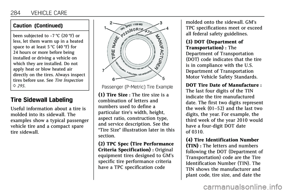
molded into its sidewall. The
examples show a typical passenger
vehicle tire and a compact spare
tire sidewall.
Passenger (P-Metric) Tire Example
(1) Tire Size:The tire size is a
combination of letters and
numbers used to define a
particular tire's width, height,
aspect ratio, construction type,
and service description. See the
“Tire Size ”illustration later in this
section.
(2) TPC Spec (Tire Performance
Criteria Specification)
:Original
equipment tires designed to GM's
specific tire performance criteria
have a TPC specification code molded onto the sidewall. GM's
TPC specifications meet or exceed
all federal safety guidelines.
(3) DOT (Department of
Transportation)
:The
Department of Transportation
(DOT) code indicates that the tire
is in compliance with the U.S.
Department of Transportation
Motor Vehicle Safety Standards.
DOT Tire Date of Manufacture
:
The last four digits of the TIN
indicate the tire manufactured
date. The first two digits represent
the week (01–52) and the last two
digits, the year. For example, the
third week of the year 2010 would
have a four-digit DOT date
of 0310.
(4) Tire Identification Number
(TIN)
:The letters and numbers
following the DOT (Department of
Transportation) code are the Tire
Identification Number (TIN). The
TIN shows the manufacturer and
plant code, tire size, and date the
Page 286 of 384
VEHICLE CARE 285
tire was manufactured. The TIN is
molded onto both sides of the tire,
although only one side may have
the date of manufacture.
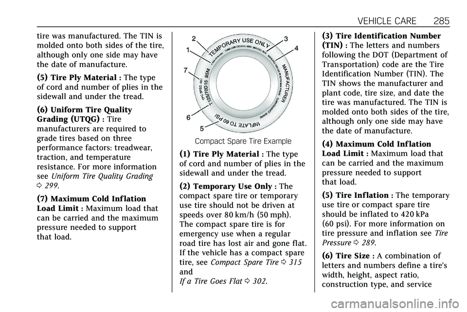
(5) Tire Ply Material
:The type
of cord and number of plies in the
sidewall and under the tread.
(6) Uniform Tire Quality
Grading (UTQG)
:Tire
manufacturers are required to
grade tires based on three
performance factors: treadwear,
traction, and temperature
resistance. For more information
see Uniform Tire Quality Grading
0 299.
(7) Maximum Cold Inf lation
Load Limit
:Maximum load that
can be carried and the maximum
pressure needed to support
that load.
Compact Spare Tire Example
(1) Tire Ply Material:The type
of cord and number of plies in the
sidewall and under the tread.
(2) Temporary Use Only
:The
compact spare tire or temporary
use tire should not be driven at
speeds over 80 km/h (50 mph).
The compact spare tire is for
emergency use when a regular
road tire has lost air and gone flat.
If the vehicle has a compact spare
tire, see Compact Spare Tire 0315
and
If a Tire Goes Flat 0302. (3) Tire Identification Number
(TIN)
:The letters and numbers
following the DOT (Department of
Transportation) code are the Tire
Identification Number (TIN). The
TIN shows the manufacturer and
plant code, tire size, and date the
tire was manufactured. The TIN is
molded onto both sides of the tire,
although only one side may have
the date of manufacture.
(4) Maximum Cold Inf lation
Load Limit
:Maximum load that
can be carried and the maximum
pressure needed to support
that load.
(5) Tire Inf lation
:The temporary
use tire or compact spare tire
should be inflated to 420 kPa
(60 psi). For more information on
tire pressure and inflation see Tire
Pressure 0289.
(6) Tire Size
:A combination of
letters and numbers define a tire's
width, height, aspect ratio,
construction type, and service
Page 287 of 384
286 VEHICLE CARE
description. The letter“T”as the
first character in the tire size
means the tire is for temporary
use only.
(7) TPC Spec (Tire Performance
Criteria Specification)
:Original
equipment tires designed to GM's
specific tire performance criteria
have a TPC specification code
molded onto the sidewall. GM's
TPC specifications meet or exceed
all federal safety guidelines.
Tire Designations
Tire Size
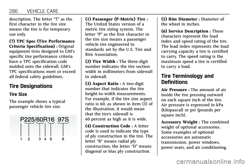
The example shows a typical
passenger vehicle tire size.
(1) Passenger (P-Metric) Tire:
The United States version of a
metric tire sizing system. The
letter “P”as the first character in
the tire size means a passenger
vehicle tire engineered to
standards set by the U.S. Tire and
Rim Association.
(2) Tire Width
:The three-digit
number indicates the tire section
width in millimeters from sidewall
to sidewall.
(3) Aspect Ratio
:A two-digit
number that indicates the tire
height-to-width measurements.
For example, if the tire size aspect
ratio is 60, as shown in item (3) of
the illustration, it would mean
that the tire's sidewall is
60 percent as high as it is wide.
(4) Construction Code
:A letter
code is used to indicate the type
of ply construction in the tire. The
letter “R”means radial ply
construction; the letter “D”means
diagonal or bias ply construction. (5) Rim Diameter
:Diameter of
the wheel in inches.
(6) Service Description
:These
characters represent the load
index and speed rating of the tire.
The load index represents the load
carrying capacity a tire is certified
to carry. The speed rating is the
maximum speed a tire is certified
to carry a load.
Tire Terminology and
Definitions
Air Pressure:The amount of air
inside the tire pressing outward
on each square inch of the tire.
Air pressure is expressed in kPa
(kilopascal) or psi (pounds per
square inch).
Accessory Weight
:The combined
weight of optional accessories.
Some examples of optional
accessories are automatic
transmission, power windows,
power seats, and air conditioning.
Page 288 of 384
VEHICLE CARE 287
Aspect Ratio:The relationship of
a tire's height to its width.
Belt
:A rubber coated layer of
cords between the plies and the
tread. Cords may be made from
steel or other reinforcing
materials.
Bead
:The tire bead contains steel
wires wrapped by steel cords that
hold the tire onto the rim.
Bias Ply Tire
:A pneumatic tire in
which the plies are laid at
alternate angles less than
90 degrees to the centerline of the
tread.
Cold Tire Pressure
:The amount
of air pressure in a tire, measured
in kPa (kilopascal) or psi (pounds
per square inch) before a tire has
built up heat from driving. See
Tire Pressure 0289.
Curb Weight
:The weight of a
motor vehicle with standard and
optional equipment including the maximum capacity of fuel, oil, and
coolant, but without passengers
and cargo.
DOT Markings
:A code molded
into the sidewall of a tire
signifying that the tire is in
compliance with the U.S.
Department of Transportation
(DOT) Motor Vehicle Safety
Standards. The DOT code includes
the Tire Identification Number
(TIN), an alphanumeric designator
which can also identify the tire
manufacturer, production plant,
brand, and date of production.
GVWR
:Gross Vehicle Weight
Rating. See Vehicle Load Limits
0 170.
GAWR FRT
:Gross Axle Weight
Rating for the front axle. See
Vehicle Load Limits 0170.
GAWR RR
:Gross Axle Weight
Rating for the rear axle. See
Vehicle Load Limits 0170. Intended Outboard Sidewall
:
The side of an asymmetrical tire
that must always face outward
when mounted on a vehicle.
Kilopascal (kPa)
:The metric unit
for air pressure.
Light Truck (LT-Metric) Tire
:A
tire used on light duty trucks and
some multipurpose passenger
vehicles.
Load Index
:An assigned number
ranging from 1 to 279 that
corresponds to the load carrying
capacity of a tire.
Maximum Inf lation Pressure
:
The maximum air pressure to
which a cold tire can be inflated.
The maximum air pressure is
molded onto the sidewall.
Maximum Load Rating
:The load
rating for a tire at the maximum
permissible inflation pressure for
that tire.