battery CADILLAC XT5 2020 Owner's Guide
[x] Cancel search | Manufacturer: CADILLAC, Model Year: 2020, Model line: XT5, Model: CADILLAC XT5 2020Pages: 384, PDF Size: 6.52 MB
Page 176 of 384
DRIVING AND OPERATING 175
the Remote Keyless Entry (RKE)
system. SeeRemote Keyless Entry
(RKE) System Operation 010.
To shift out of P (Park), the vehicle
must be turned on and the brake
pedal must be applied.
Stopping the Engine/OFF (No
Indicator Light) : When the vehicle is
stopped, press ENGINE START/STOP
once to turn the engine off.
If the vehicle is in P (Park), the
ignition will turn off, and Retained
Accessory Power (RAP) will remain
active. See Retained Accessory Power
(RAP) 0180.
If the vehicle is in R (Reverse),
D (Drive) or M (Manual Mode), the
vehicle will shift to P (Park), the
ignition will turn off, and Retained
Accessory Power (RAP) will remain
active. See Retained Accessory Power
(RAP) 0180.
If the vehicle is in N (Neutral), the
ignition will return to ACC/
ACCESSORY and display the message
SHIFT TO PARK in the Driver Information Center (DIC). When the
vehicle is shifted into P (Park), the
ignition will turn off.
{Warning
Turning off the vehicle while
moving may cause loss of power
assist in the brake and steering
systems and disable the airbags.
While driving, only shut the vehicle
off in an emergency.
If the vehicle must be shut off in an
emergency: 1. Brake using a firm and steady pressure. Do not pump the
brakes repeatedly. This may
deplete power assist, requiring
increased brake pedal force.
2. Shift the vehicle to N (Neutral). This can be done while the
vehicle is moving. After shifting
to N (Neutral), firmly apply the
brakes and steer the vehicle to a
safe location.
3. Come to a complete stop and shift to P (Park). 4. Set the parking brake. See
Electric Parking Brake 0191.
Press ENGINE START/STOP to
turn the vehicle off.
If the vehicle cannot be pulled over
and must be shut off while driving,
press and hold ENGINE START/STOP
for longer than two seconds, or press
twice in five seconds.
ACC/ACCESSORY (Amber Indicator
Light) : This mode allows you to use
some electrical accessories when the
engine is off.
With the ignition off, pressing
ENGINE START/STOP once without
the brake pedal applied will place the
ignition system in ACC/ACCESSORY.
The ignition will switch from ACC/
ACCESSORY to OFF after 10 minutes
to prevent battery rundown.
ON/RUN/START (Green Indicator
Light) : This mode is for driving and
starting. With the ignition off and the
brake pedal applied, pressing ENGINE
START/STOP once will place the
ignition system in ON/RUN/START.
Once engine cranking begins, release
the button. Engine cranking will
Page 177 of 384
176 DRIVING AND OPERATING
continue until the engine starts. The
ignition will then remain on. See
Starting the Engine0176.
Service Mode
This mode is available to verify the
proper operation of the malfunction
indicator lamp as may be required for
emissions inspection purposes and for
service and diagnostics. See Automatic
Transmission 0184.
With the vehicle off, and the brake
pedal not applied, pressing and
holding ENGINE START/STOP for
more than five seconds will place the
vehicle in Service Mode. The
instruments and audio systems will
operate as they do in ON/RUN, but
the vehicle will not be able to be
driven. The engine will not start in
Service Mode. Press ENGINE START/
STOP again to turn the vehicle off.
Starting the Engine
Place the transmission in the proper
gear, P (Park) or N (Neutral). To restart
the engine when the vehicle is already
moving, use N (Neutral).
Caution
Do not try to shift to P (Park) if the
vehicle is moving. If you do, you
could damage the transmission.
Shift to P (Park) only when the
vehicle is stopped.
Caution
If you add electrical parts or
accessories, you could change the
way the engine operates. Any
resulting damage would not be
covered by the vehicle warranty. See
Add-On Electrical Equipment 0246.
To start the vehicle: 1. With the Keyless Access system, the RKE transmitter must be in
the vehicle. Press ENGINE
START/STOP with the brake
pedal applied. When the engine
begins cranking, let go of the
button. The idle speed will go down as the engine warms up.
Do not race the engine
immediately after starting it.
If the RKE transmitter is not in
the vehicle, if there is
interference, or if the RKE
battery is low, a Driver
Information Center (DIC)
message will display. See
Remote
Keyless Entry (RKE) System
Operation 010.Caution
Cranking the engine for long
periods of time, by pressing
ENGINE START/STOP immediately
after cranking has ended, can
overheat and damage the cranking
motor, and drain the battery. Wait
at least 15 seconds between each
try, to let the cranking motor
cool down.
2. If the engine does not start after five to 10 seconds, especially in
very cold weather (below −18 °C
or 0 °F), it could be flooded with
too much gasoline. Try pushing
Page 178 of 384
DRIVING AND OPERATING 177
the accelerator pedal all the way
to the floor and hold it there,
then press ENGINE START/STOP
for up to a maximum of
15 seconds. Wait at least
15 seconds between each try, to
allow the cranking motor to cool
down. When the engine starts,
let go of the button and the
accelerator. If the vehicle starts
briefly but then stops again, do
the same thing. This clears the
extra gasoline from the engine.
Do not race the engine
immediately after starting it.
Operate the engine and
transmission gently until the oil
warms up and lubricates all
moving parts.
Stop/Start System
The Stop/Start system will shut off
the engine to help conserve fuel.
It has components designed for the
increased number of starts.
{Warning
The automatic engine Stop/Start
feature causes the engine to shut
off while the vehicle is still on. Do
not exit the vehicle before shifting
to P (Park). The vehicle may restart
and move unexpectedly. Always
shift to P (Park), and then turn the
ignition off before exiting the
vehicle.
Auto Engine Stop/Start
When the brakes are applied and the
vehicle is at a complete stop, the
engine may turn off. When stopped,
the tachometer displays AUTO STOP.
See Tachometer 0111. When the brake
pedal is released or the accelerator
pedal is pressed, the engine will
restart.
To maintain vehicle performance,
other conditions may cause the engine
to automatically restart before the
brake pedal is released.
Auto Stops may not occur and/or Auto
Starts may occur because: .
The climate control settings
require the engine to be running
to cool or heat the vehicle interior.
. The vehicle battery charge is low.
. The vehicle battery has recently
been disconnected.
. Minimum vehicle speed has not
been reached since the last
Auto Stop.
. The accelerator pedal is pressed.
. The engine or transmission is not
at the required operating
temperature.
. The outside temperature is not in
the required operating range.
. The vehicle is in any gear other
than D (Drive).
. Driver modes have been selected.
. The vehicle is on a steep hill or
grade.
. The driver door has been opened
or the driver seat belt has been
unbuckled.
. The hood has been opened.
Page 182 of 384

DRIVING AND OPERATING 181
inadvertent shifting out of P (Park)
unless the ignition is on, the brake
pedal is applied, and the shift lock
release button is pressed.
The shift lock control is always
functional except in the case of an
uncharged or low voltage (less than
9-volt) battery.
If the vehicle has an uncharged
battery or a battery with low voltage,
try charging or jump starting the
battery. SeeJump Starting - North
America 0316.
To shift out of P (Park): 1. Ensure the engine is running.
2. Apply the brake pedal.
3. Press the shift lock release button.
4. Move the shift lever to the desired position.
5. The P indicator will turn white and the gear indicator on the
shift lever will turn red when the
vehicle is no longer in P (Park).
6. After releasing the shift lever, it will return to the center position. If the vehicle cannot shift from
P (Park), a Driver Information
Center (DIC) message will be
displayed. See your dealer for service.
Manual Park Release
{Warning
The transmission will be placed in
N (Neutral) when the manual park
release is pulled. The vehicle can
roll and you or others could be
injured. Ensure the vehicle is on
level ground.
Caution
The manual park release is not
intended to be used for towing.
Damage may result from using the
manual park release in this way.
The repairs would not be covered
by the vehicle warranty.
This vehicle includes a manual park
release that can be used to shift the
vehicle into N (Neutral) when the
engine is not running.
Pulling the manual park release while
the vehicle is on or turning the
ignition on while the manual park
release is pulled, will cause a DIC
message to display.
To place the vehicle in N (Neutral)
using the manual park release:
1. Ensure the vehicle is on level ground and set the parking
brake. Release the brake pedal.
2. Turn the vehicle off.
Page 192 of 384

DRIVING AND OPERATING 191
If there is a problem with ABS, this
warning light stays on. SeeAntilock
Brake System (ABS) Warning Light
0 118.
ABS does not change the time needed
to get a foot on the brake pedal and
does not always decrease stopping
distance. If you get too close to the
vehicle ahead, there will not be
enough time to apply the brakes if
that vehicle suddenly slows or stops.
Always leave enough room ahead to
stop, even with ABS.
Using ABS
Do not pump the brakes. Just hold the
brake pedal down firmly. Hearing or
feeling ABS operate is normal.
Braking in Emergencies
ABS allows steering and braking at the
same time. In many emergencies,
steering can help even more than
braking.
Electric Parking Brake
The vehicle has an Electric Parking
Brake (EPB). The EPB can always be
activated, even if the ignition is off. To
prevent draining the battery, avoid
repeated cycles of the EPB system
when the engine is not running. The system has a
Y,f, or PARK
Electric Parking Brake light, and a
8
Service Parking Brake light. See
Electric Parking Brake Light 0118 and
Service Electric Parking Brake Light
0 118.
Before leaving the vehicle, check for
the
Y,f, or PARK light to ensure
that the parking brake is applied.
EPB Apply
To apply the EPB:
1. Be sure the vehicle is at a complete stop.
2. Press the EPB switch momentarily.
The
Y,f, or PARK light will flash
and then stay on once the EPB is fully
applied. If the
Y,f, or PARK light
flashes continuously, then the EPB is
only partially applied or there is a
problem with the EPB. A DIC message
will display. Release the EPB and try
to apply it again. If the light does not
come on, or keeps flashing, have the
vehicle serviced. Do not drive the
Page 245 of 384
244 DRIVING AND OPERATING
Tail/Parking
LampsGray/Brown
Reverse Lamps White/Green
Battery Feed Red/Green
Ground Black
Electric Trailer
Brake* Blue
* Circuit powered by electric trailer
brake control wiring provisions.
Electric Trailer Brake Control
Wiring Provisions
Wiring provisions for an aftermarket
electric trailer brake controller are
included with the vehicle as part of
the trailer wiring package. The
harness contains the following
circuits: Electric Trailer
Brakes Blue
Battery Feed Red/Green or
Red/Blue
Brake Apply
Signal White/Blue
Ground Black Refer to the aftermarket electric trailer
brake controller owner's manual to
determine wire color coding of the
electric trailer brake controller. The
wire colors on the brake controller
may be different from the vehicle. The
electric trailer brake controller should
be installed by your dealer or a
qualified service center.
If equipped, there are four blunt cut
wires inside the front driver side
instrument panel. It will be necessary
to have a technician connect the
12-volt power to the engine
compartment fuse block.Trailer Lamps
Always check all trailer lamps are
working at the beginning of each trip,
and periodically on longer trips.
Turn Signals When Towing a
Trailer
When properly connected, the trailer
turn signals will illuminate to indicate
the vehicle is turning, changing lanes,
or stopping. When towing a trailer,
the arrows on the instrument cluster
will illuminate even if the trailer is not
properly connected or the bulbs are
burned out.
Always check all trailer lamps are
working at the beginning of each trip,
and periodically on longer trips.
Trailer Sway Control (TSC)
Vehicles with StabiliTrak/Electronic
Stability Control (ESC) have a Trailer
Sway Control (TSC) feature. Trailer
sway is unintended side-to-side
motion of a trailer while towing. If the
vehicle is towing a trailer and the TSC
detects that sway is increasing, the
vehicle brakes are selectively applied
at each wheel, to help reduce
excessive trailer sway. If equipped with
the Integrated Trailer Brake Control
(ITBC) system, and the trailer has an
electric brake system, StabiliTrak/ESC
may also apply the trailer brakes.
Page 247 of 384

246 DRIVING AND OPERATING
Conversions and
Add-Ons
Add-On Electrical
Equipment
{Warning
The Data Link Connector (DLC) is
used for vehicle service and
Emission Inspection/Maintenance
testing. SeeMalfunction Indicator
Lamp (Check Engine Light) 0115.
A device connected to the DLC —
such as an aftermarket fleet or
driver-behavior tracking device —
may interfere with vehicle systems.
This could affect vehicle operation
and cause a crash. Such devices
may also access information stored
in the vehicle’s systems.
Caution
Some electrical equipment can
damage the vehicle or cause
components to not work and would
not be covered by the vehicle
warranty. Always check with your
dealer before adding electrical
equipment.
Add-on equipment can drain the
vehicle's 12-volt battery, even if the
vehicle is not operating.
The vehicle has an airbag system.
Before attempting to add anything
electrical to the vehicle, see Servicing
the Airbag-Equipped Vehicle 071 and
Adding Equipment to the
Airbag-Equipped Vehicle 071.
Page 248 of 384
VEHICLE CARE 247
Vehicle Care
General Information
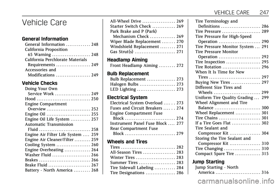
General Information . . . . . . . . . . . . . 248
California Proposition65 Warning . . . . . . . . . . . . . . . . . . . . . 248
California Perchlorate Materials Requirements . . . . . . . . . . . . . . . . . . . 249
Accessories and Modifications . . . . . . . . . . . . . . . . . . . 249
Vehicle Checks
Doing Your OwnService Work . . . . . . . . . . . . . . . . . . . . 249
Hood . . . . . . . . . . . . . . . . . . . . . . . . . . . . . . 250
Engine Compartment Overview . . . . . . . . . . . . . . . . . . . . . . . . . 252
Engine Oil . . . . . . . . . . . . . . . . . . . . . . . . . 255
Engine Oil Life System . . . . . . . . . . . 257
Automatic Transmission Fluid . . . . . . . . . . . . . . . . . . . . . . . . . . . . . 258
Engine Air Filter Life System . . . . 259
Engine Air Cleaner/Filter . . . . . . . . . 259
Cooling System . . . . . . . . . . . . . . . . . . . 260
Engine Overheating . . . . . . . . . . . . . . 264
Washer Fluid . . . . . . . . . . . . . . . . . . . . . 266
Brakes . . . . . . . . . . . . . . . . . . . . . . . . . . . . . 266
Brake Fluid . . . . . . . . . . . . . . . . . . . . . . . 267
Battery - North America . . . . . . . . . 268 All-Wheel Drive . . . . . . . . . . . . . . . . . . 269
Starter Switch Check . . . . . . . . . . . . . 269
Park Brake and P (Park)
Mechanism Check . . . . . . . . . . . . . . 269
Wiper Blade Replacement . . . . . . . 270
Windshield Replacement . . . . . . . . 271
Gas Strut(s) . . . . . . . . . . . . . . . . . . . . . . . 271
Headlamp Aiming
Front Headlamp Aiming . . . . . . . . . 272
Bulb Replacement
Bulb Replacement . . . . . . . . . . . . . . . . 273
Halogen Bulbs . . . . . . . . . . . . . . . . . . . . 273
LED Lighting . . . . . . . . . . . . . . . . . . . . . 273
Electrical System
Electrical System Overload . . . . . . 273
Fuses and Circuit Breakers . . . . . . 274
Engine Compartment Fuse
Block . . . . . . . . . . . . . . . . . . . . . . . . . . . . 274
Instrument Panel Fuse Block . . . . 277
Rear Compartment Fuse Block . . . . . . . . . . . . . . . . . . . . . . . . . . . . 279
Wheels and Tires
Tires . . . . . . . . . . . . . . . . . . . . . . . . . . . . . . . 282
All-Season Tires . . . . . . . . . . . . . . . . . . 283
Winter Tires . . . . . . . . . . . . . . . . . . . . . . 283
Summer Tires . . . . . . . . . . . . . . . . . . . . 283
Tire Sidewall Labeling . . . . . . . . . . . 284
Tire Designations . . . . . . . . . . . . . . . . . 286 Tire Terminology and
Definitions . . . . . . . . . . . . . . . . . . . . . . 286
Tire Pressure . . . . . . . . . . . . . . . . . . . . . . 289
Tire Pressure for High-Speed Operation . . . . . . . . . . . . . . . . . . . . . . . . 290
Tire Pressure Monitor System . . . 291
Tire Pressure Monitor Operation . . . . . . . . . . . . . . . . . . . . . . . . 292
Tire Inspection . . . . . . . . . . . . . . . . . . . 295
Tire Rotation . . . . . . . . . . . . . . . . . . . . . 296
When It Is Time for New Tires . . . . . . . . . . . . . . . . . . . . . . . . . . . . . 297
Buying New Tires . . . . . . . . . . . . . . . . 297
Different Size Tires and Wheels . . . . . . . . . . . . . . . . . . . . . . . . . . 299
Uniform Tire Quality Grading . . . 299
Wheel Alignment and Tire Balance . . . . . . . . . . . . . . . . . . . . . . . . . . 300
Wheel Replacement . . . . . . . . . . . . . . 301
Tire Chains . . . . . . . . . . . . . . . . . . . . . . . 301
If a Tire Goes Flat . . . . . . . . . . . . . . . . 302
Tire Sealant and Compressor Kit . . . . . . . . . . . . . . . . . 304
Storing the Tire Sealant and Compressor Kit . . . . . . . . . . . . . . . . . 310
Tire Changing . . . . . . . . . . . . . . . . . . . . . 310
Compact Spare Tire . . . . . . . . . . . . . . 315
Jump Starting
Jump Starting - North America . . . . . . . . . . . . . . . . . . . . . . . . . 316
Page 249 of 384

248 VEHICLE CARE
Towing the Vehicle
Towing the Vehicle . . . . . . . . . . . . . . . 319
Recreational Vehicle Towing . . . . 320
Appearance Care
Exterior Care . . . . . . . . . . . . . . . . . . . . . . 323
Interior Care . . . . . . . . . . . . . . . . . . . . . . 327
Floor Mats . . . . . . . . . . . . . . . . . . . . . . . . 330
General Information
For service and parts needs, visit your
dealer. You will receive genuine GM
parts and GM-trained and supported
service people.
Genuine GM parts have one of these
marks:
California Proposition
65 Warning
{Warning
Most motor vehicles, including this
one, as well as many of its service
parts and fluids, contain and/or
emit chemicals known to the State
of California to cause cancer and
birth defects or other reproductive
harm. Engine exhaust, many parts
and systems, many fluids, and
some component wear by-products
contain and/or emit these
chemicals. For more information go
to www.P65Warnings.ca.gov/
passenger-vehicle.
See Battery - North America 0268 and
Jump Starting - North America 0316
and the back cover.
Page 254 of 384
VEHICLE CARE 253
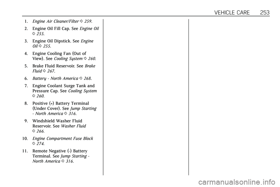
1.Engine Air Cleaner/Filter 0259.
2. Engine Oil Fill Cap. See Engine Oil
0 255.
3. Engine Oil Dipstick. See Engine
Oil 0255.
4. Engine Cooling Fan (Out of View). See Cooling System 0260.
5. Brake Fluid Reservoir. See Brake
Fluid 0267.
6. Battery - North America 0268.
7. Engine Coolant Surge Tank and Pressure Cap. See Cooling System
0 260.
8. Positive (+) Battery Terminal (Under Cover). See Jump Starting
- North America 0316.
9. Windshield Washer Fluid Reservoir. See Washer Fluid
0 266.
10. Engine Compartment Fuse Block
0274.
11. Remote Negative (-) Battery Terminal. See Jump Starting -
North America 0316.