parking brake CADILLAC XT5 2020 Owner's Guide
[x] Cancel search | Manufacturer: CADILLAC, Model Year: 2020, Model line: XT5, Model: CADILLAC XT5 2020Pages: 384, PDF Size: 6.52 MB
Page 265 of 384
264 VEHICLE CARE
surge tank until the level reaches
the mark pointed to on the front
of the coolant surge tank.
5. Replace the pressure cap tightly.
6. Verify coolant level after the engine is shut off and the
coolant is cold. If necessary,
repeat coolant fill procedure
Step 1–6.
Caution
If the pressure cap is not tightly
installed, coolant loss and engine
damage may occur. Be sure the cap
is properly and tightly secured.
Automatic Coolant Service Fill
Instructions (2.0L Engine Only)
If equipped, this feature assists in
filling and removing air from the
cooling system after service of
components or when coolant is added
after being too low.
To activate the fill and air removal
process:
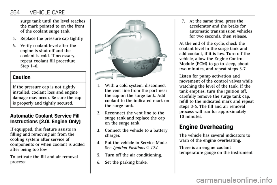
1. With a cold system, disconnectthe vent line from the port near
the cap on the surge tank. Add
coolant to the indicated mark on
the surge tank.
2. Reconnect the vent line to the surge tank and replace the cap
on the surge tank.
3. Connect the vehicle to a battery charger.
4. Put the vehicle in Service Mode. See Ignition Positions 0174.
5. Turn off the air conditioning.
6. Set the parking brake. 7. At the same time, press the
accelerator and the brake for
automatic transmission vehicles
for two seconds, then release.
At the end of the cycle, check the
coolant level in the surge tank and
add coolant, if it is low. Turn off the
vehicle, allow the Engine Control
Module (ECM) to go to sleep, about
two minutes, and repeat steps 3-7.
Listen for pump activation and
movement of the control valves while
watching the level of the tank. If the
tank empties, turn the ignition off,
carefully remove the surge tank cap,
refill to the indicated mark and repeat
steps 3-6. The fill and air removal
process will run for approximately
10 minutes.
Engine Overheating
The vehicle has several indicators to
warn of the engine overheating.
There is an engine coolant
temperature gauge on the instrument
Page 270 of 384

VEHICLE CARE 269
Warning (Continued)
chemicals known to the State of
California to cause cancer and birth
defects or other reproductive harm.
Batteries also contain other
chemicals known to the State of
California to cause cancer.WASH
HANDS AFTER HANDLING. For
more information go to
www.P65Warnings.ca.gov/
passenger-vehicle.
See California Proposition 65 Warning
0 248 and the back cover.
Vehicle Storage
{Warning
Batteries have acid that can burn
you and gas that can explode. You
can be badly hurt if you are not
careful. See Jump Starting - North
America 0316 for tips on working
around a battery without
getting hurt. Infrequent Usage: Remove the black,
negative (−) cable from the battery to
keep the battery from running down.
Extended Storage: Remove the black,
negative (−) cable from the battery or
use a battery trickle charger.
All-Wheel Drive
Transfer Case
Under normal driving conditions,
transfer case fluid does not require
maintenance unless there is a fluid
leak or unusual noise. If required,
have the transfer case serviced by
your dealer.
Starter Switch Check
{Warning
When you are doing this inspection,
the vehicle could move suddenly.
If the vehicle moves, you or others
could be injured.
1. Before starting this check, be
sure there is enough room
around the vehicle.
2. Apply both the parking brake and the regular brake.
Do not use the accelerator pedal,
and be ready to turn off the
engine immediately if it starts.
3. Try to start the engine in each gear. The vehicle should start
only in P (Park) or N (Neutral).
If the vehicle starts in any other
position, contact your dealer for
service.
Park Brake and P (Park)
Mechanism Check
{Warning
When you are doing this check, the
vehicle could begin to move. You or
others could be injured and
property could be damaged. Make
sure there is room in front of the
vehicle in case it begins to roll. Be
(Continued)
Page 271 of 384
270 VEHICLE CARE
Warning (Continued)
ready to apply the regular brake at
once should the vehicle begin
to move.
Park on a fairly steep hill, with the
vehicle facing downhill. Keeping your
foot on the regular brake, set the
parking brake.
. To check the parking brake's
holding ability: With the engine
running and the transmission in
N (Neutral), slowly remove foot
pressure from the regular brake
pedal. Do this until the vehicle is
held by the parking brake only.
. To check the P (Park) mechanism's
holding ability: With the engine
running, shift to P (Park). Then
release the parking brake followed
by the regular brake.
Contact your dealer if service is
required.
Wiper Blade Replacement
Windshield wiper blades should be
inspected for wear or cracking.
It is a good idea to clean or replace
the wiper blade assembly on a regular
basis or when worn. For proper
windshield wiper blade length and
type, see Maintenance Replacement
Parts 0343.
Caution
Allowing the wiper arm to touch
the windshield when no wiper blade
is installed could damage the
windshield. Any damage that occurs
would not be covered by the vehicle
warranty. Do not allow the wiper
arm to touch the windshield.
Front Wiper Blade Replacement
To replace the wiper blade assembly:
1. Pull the windshield wiper assembly away from the
windshield.
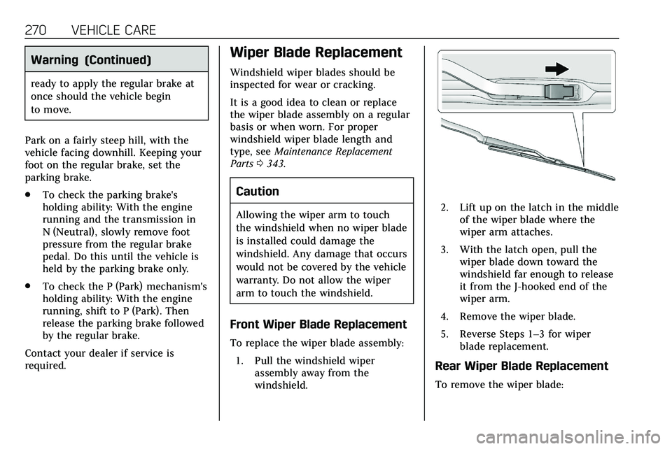
2. Lift up on the latch in the middleof the wiper blade where the
wiper arm attaches.
3. With the latch open, pull the wiper blade down toward the
windshield far enough to release
it from the J-hooked end of the
wiper arm.
4. Remove the wiper blade.
5. Reverse Steps 1–3 for wiper blade replacement.
Rear Wiper Blade Replacement
To remove the wiper blade:
Page 277 of 384

276 VEHICLE CARE
FusesUsage
F5 DC DC transformer 2
F6 Amplifier 1
F7 Front blower
F8 Starter 3
F9 –
F10 –
F11 –
F12 Front wiper
F13 Starter 2
F14 LED/Automatic headlamp leveling
F15 Rear wiper 1
F16 –
F17 –
F18 Automatic headlamp leveling module
F19 –
F20 –
F21 –
F22 Electronic brake control module Fuses
Usage
F23 Parking/Trailer lamps
F24 Right trailer stoplamp/Turnlamp
F25 Steering column lock
F26 –
F27 Left trailer stoplamp/ Turnlamp
F28 –
F29 –
F30 Washer pump
F31 –
F32 –
F33 Fog lamps
F34 Horn
F35 –
F36 Headlamp high-beam –left
F37 Headlamp high-beam –right
F38 Automatic headlamp leveling motor Fuses
Usage
F39 Transmission control module/Battery 1
F40 Left rear bus electrical center/Ignition
F41 Instrument cluster
F42 Heating, ventilation, and air conditioning
F43 Head-Up display
F44 Electronic brake control module
electric brake booster/
Run/Crank
F45 –
F46 –
F47 –
F48 Rear wiper 2
F49 Interior rearview mirror/Trailer
F50 Fuel system control module
F51 Heated steering wheel
F52 Air conditioning clutch
Page 282 of 384
VEHICLE CARE 281
FusesUsage
F22 –
F23 –
F24 Passenger window switch
F25 –
F26 Trailer brake
F27 Driver ventilated seat/ Lumbar
F28 Passive entry/Passive start
F29 –
F30 Canister vent
F31 –
F32 Heated mirror
F33 –
F34 Liftgate module
F35 Fuel system control module
F36 Passenger ventilated seat/Lumbar
F37 – Fuses
Usage
F38 Window module
F39 Rear closure
F40 Memory seat module
F41 Automatic occupancy sensor
F42 Trailer battery 2
F43 –
F44 –
F45 Liftgate motor
F46 Rear heated seats
F47 –
F48 Glass break sensor
F49 –
F50 –
F51 –
F52 Active dampening system module
F53 Rear parking aid module/Video/USB/
Spare Fuses
Usage
F54 External object calculating/Side blind
zone alert
F55 –
F56 Universal garage door opener/Rain sensor
F57 Theft deterrent
Circuit
Breakers Usage
CB1 –
CB2 –
CB3 Rear auxiliary power outlet
Relays Usage
K1 –
K2 –
Page 294 of 384

VEHICLE CARE 293
TPMS Malfunction Light and
Message
The TPMS will not function properly if
one or more of the TPMS sensors are
missing or inoperable. When the
system detects a malfunction, the low
tire pressure warning light flashes for
about one minute and then stays on
for the remainder of the ignition cycle.
A DIC warning message also displays.
The malfunction light and DIC
warning message come on at each
ignition cycle until the problem is
corrected. Some of the conditions that
can cause these to come on are:
.One of the road tires has been
replaced with the spare tire. The
spare tire does not have a TPMS
sensor. The malfunction light and
DIC message should go off after
the road tire is replaced and the
sensor matching process is
performed successfully. See “TPMS
Sensor Matching Process ”later in
this section.
. The TPMS sensor matching
process was not done or not
completed successfully after
rotating the tires. The malfunction light and the DIC message should
go off after successfully
completing the sensor matching
process. See "TPMS Sensor
Matching Process" later in this
section.
. One or more TPMS sensors are
missing or damaged. The
malfunction light and the DIC
message should go off when the
TPMS sensors are installed and
the sensor matching process is
performed successfully. See your
dealer for service.
. Replacement tires or wheels do
not match the original equipment
tires or wheels. Tires and wheels
other than those recommended
could prevent the TPMS from
functioning properly. See Buying
New Tires 0297.
. Operating electronic devices or
being near facilities using radio
wave frequencies similar to the
TPMS could cause the TPMS
sensors to malfunction.
If the TPMS is not functioning
properly it cannot detect or signal a
low tire pressure condition. See your dealer for service if the TPMS
malfunction light and DIC message
come on and stay on.Tire Fill Alert (If Equipped)
This feature provides visual and
audible alerts outside the vehicle to
help when inflating an underinflated
tire to the recommended cold tire
pressure.
When the low tire pressure warning
light comes on:
1. Park the vehicle in a safe, level place.
2. Set the parking brake firmly.
3. Place the vehicle in P (Park).
4. Add air to the tire that is underinflated. The turn signal
lamp will flash.
When the recommended
pressure is reached, the horn
sounds once and the turn signal
lamp will stop flashing and
briefly turn solid.
Page 296 of 384

VEHICLE CARE 295
www.gmtoolsandequipment.com or
call 1-800-GM TOOLS
(1-800-468-6657).
There are two minutes to match the
first tire/wheel position, and
five minutes overall to match all four
tire/wheel positions. If it takes longer,
the matching process stops and must
be restarted.
The TPMS sensor matching process is:1. Set the parking brake.
2. Place the vehicle in Service Mode. See Ignition Positions
0 174.
3. Make sure the Tire Pressure info display option is turned on. The
info displays on the DIC can be
turned on and off through the
Options menu. See Driver
Information Center (DIC) 0124.
4. Use the five-way DIC control on the right side of the steering
wheel to scroll to the Tire
Pressure screen under the DIC
info page. See Driver Information
Center (DIC) 0124. 5. Press and hold SEL in the center
of the five-way DIC control.
The horn sounds twice to signal
the receiver is in relearn mode
and the TIRE LEARNING ACTIVE
message displays on the DIC
screen.
6. Start with the driver side front tire.
7. Place the relearn tool against the tire sidewall, near the valve stem.
Then press the button to activate
the TPMS sensor. A horn chirp
confirms that the sensor
identification code has been
matched to this tire and wheel
position.
8. Proceed to the passenger side front tire, and repeat Step 7.
9. Proceed to the passenger side rear tire, and repeat Step 7.
10. Proceed to the driver side rear tire, and repeat Step 7. The horn
sounds two times to indicate the
sensor identification code has
been matched to the driver side
rear tire, and the TPMS sensor
matching process is no longer active. The TIRE LEARNING
ACTIVE message on the DIC
display screen goes off.
11. Turn the vehicle off.
12. Set all four tires to the recommended air pressure level
as indicated on the Tire and
Loading Information label.
Tire Inspection
We recommend that the tires,
including the spare tire, if the
vehicle has one, be inspected for
signs of wear or damage at least
once a month.
Replace the tire if:
.The indicators at three or more
places around the tire can
be seen.
.There is cord or fabric showing
through the tire's rubber.
.The tread or sidewall is
cracked, cut, or snagged deep
enough to show cord or fabric.
Page 304 of 384

VEHICLE CARE 303
{Warning
Lifting a vehicle and getting under
it to do maintenance or repairs is
dangerous without the appropriate
safety equipment and training. If a
jack is provided with the vehicle, it
is designed only for changing a flat
tire. If it is used for anything else,
you or others could be badly injured
or killed if the vehicle slips off the
jack. If a jack is provided with the
vehicle, only use it for changing a
flat tire.
If a tire goes flat, avoid further tire
and wheel damage by driving slowly
to a level place, well off the road,
if possible. Turn on the hazard
warning flashers. See Hazard Warning
Flashers 0143.
{Warning
Changing a tire can be dangerous.
The vehicle can slip off the jack and
roll over or fall causing injury or
(Continued)
Warning (Continued)
death. Find a level place to change
the tire. To help prevent the vehicle
from moving:
1. Set the parking brake firmly.
2. Put an automatictransmission in P (Park) or a
manual transmission in
1 (First) or R (Reverse).
3. Turn off the engine and do not restart while the vehicle
is raised.
4. Do not allow passengers to remain in the vehicle.
5. Place wheel blocks, if equipped, on both sides of
the tire at the opposite corner
of the tire being changed.
This vehicle may come with a jack
and spare tire or a tire sealant and
compressor kit. To use the jacking
equipment to change a spare tire
safely, follow the instructions below.
Then see Tire Changing 0310. To use the tire sealant and compressor kit,
see
Tire Sealant and Compressor Kit
0 304.
When the vehicle has a flat tire (2),
use the following example as a guide
to assist you in the placement of
wheel blocks (1), if equipped.
1. Wheel Block (If Equipped)
2. Flat Tire
The following information explains
how to repair or change a tire.
Page 318 of 384

VEHICLE CARE 317
SeeCalifornia Proposition 65 Warning
0 248 and the back cover.
{Warning
Batteries can hurt you. They can be
dangerous because:
. They contain acid that can
burn you.
. They contain gas that can
explode or ignite.
. They contain enough
electricity to burn you.
If you do not follow these steps
exactly, some or all of these things
can hurt you.
Caution
Ignoring these steps could result in
costly damage to the vehicle that
would not be covered by the vehicle
warranty. Trying to start the vehicle
by pushing or pulling it will not
work, and it could damage the
vehicle.
3.6L V6 Shown, 2.0L L4 Similar
1. Discharged Remote Battery Positive Terminal
2. Discharged Remote Battery Negative Ground Terminal
3. Good Battery Negative Terminal
4. Good Battery Positive Terminal
The jump start remote positive
terminal (1) and the remote negative
ground terminal (2) for the discharged
battery are on the driver side of the
vehicle. The jump start negative terminal (3)
and positive terminal (4) are on the
battery of the vehicle providing the
jump start.
The positive jump start connection for
the discharged battery is under a
cover. Remove the cover to expose the
terminal.
1. Check the other vehicle. It must have a 12-volt battery with a
negative ground system.
Caution
If the other vehicle does not have a
12-volt system with a negative
ground, both vehicles can be
damaged. Only use a vehicle that
has a 12-volt system with a
negative ground for jump starting.
2. Position the two vehicles so that they are not touching.
3. Set the parking brake firmly and put the transmission in P (Park).
See Shifting Into Park 0180.
Page 322 of 384
VEHICLE CARE 321
Dinghy Towing
Caution
If the vehicle is towed with all four
wheels on the ground, the
drivetrain components could be
damaged. The repairs would not be
covered by the vehicle warranty. Do
not tow the vehicle with all four
wheels on the ground.
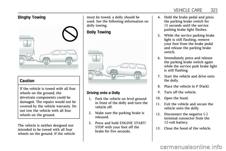
The vehicle is neither designed nor
intended to be towed with all four
wheels on the ground. If the vehicle must be towed, a dolly should be
used. See the following information on
dolly towing.
Dolly Towing
Driving onto a Dolly
1. Park the vehicle on level ground in front of the dolly and turn the
vehicle off.
2. Make sure the parking brake is released.
3. Press and hold ENGINE START/ STOP with your foot off the
brake for five seconds. 4. Hold the brake pedal and press
the parking brake switch for
15 seconds until the service
parking brake light flashes.
5. While the service parking brake light is still flashing, remove
your foot from the brake pedal
and release the parking brake
switch.
6. Immediately press and release the parking brake switch again
while the service park brake light
is still flashing.
7. Start the vehicle and drive onto the dolly.
8. Place the vehicle in P (Park).
9. Turn off the vehicle.
10. Open the hood.
11. Exit the vehicle and secure the vehicle onto the dolly.
12. Disconnect the negative (–) terminal connector from the
12-volt battery.
13. Close the hood of the vehicle.