sensor CHERY TIGGO 2009 Service Repair Manual
[x] Cancel search | Manufacturer: CHERY, Model Year: 2009, Model line: TIGGO, Model: CHERY TIGGO 2009Pages: 1903, PDF Size: 33.38 MB
Page 18 of 1903
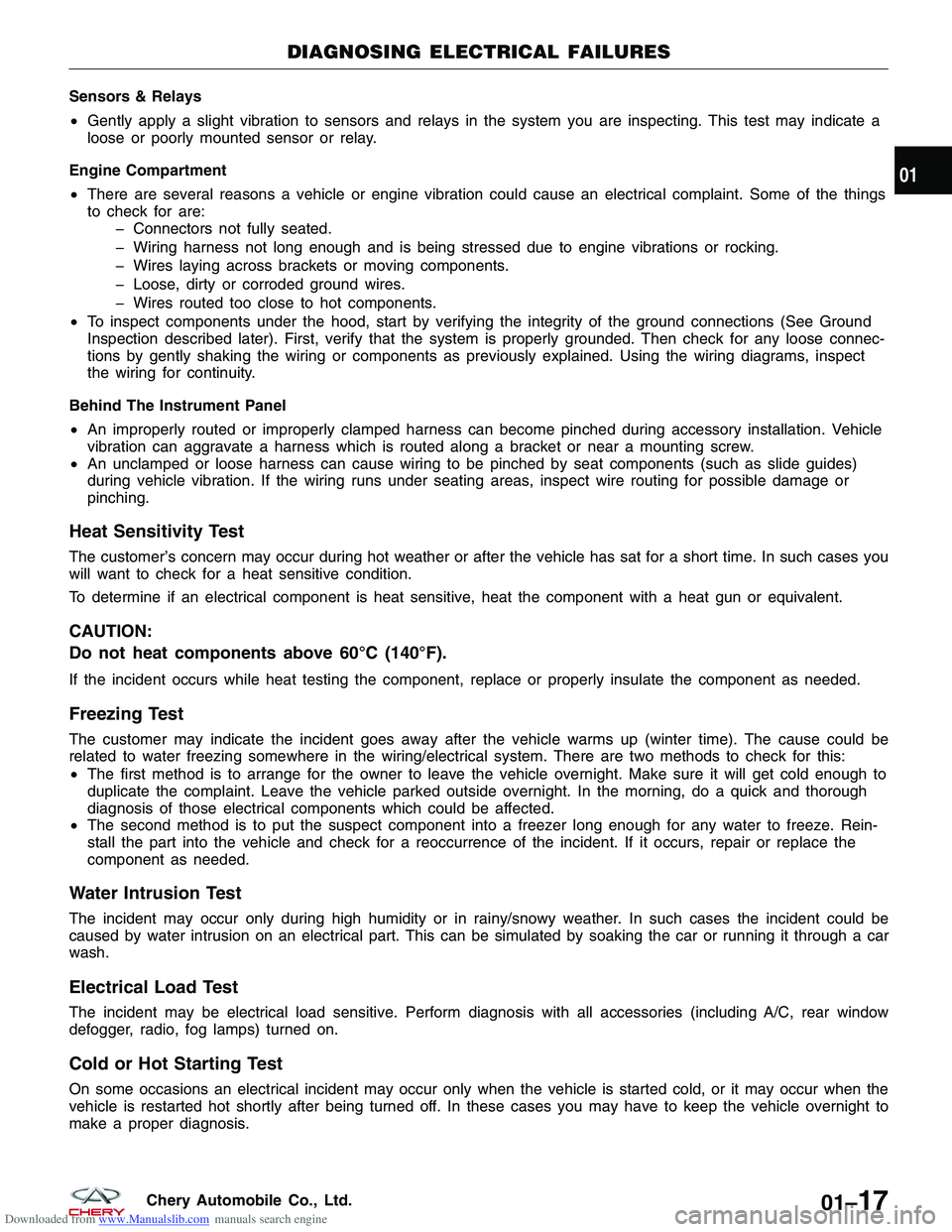
Downloaded from www.Manualslib.com manuals search engine Sensors & Relays
•Gently apply a slight vibration to sensors and relays in the system you are inspecting. This test may indicate a
loose or poorly mounted sensor or relay.
Engine Compartment
• There are several reasons a vehicle or engine vibration could cause an electrical complaint. Some of the things
to check for are:
� Connectors not fully seated.
� Wiring harness not long enough and is being stressed due to engine vibrations or rocking.
� Wires laying across brackets or moving components.
� Loose, dirty or corroded ground wires.
� Wires routed too close to hot components.
• To inspect components under the hood, start by verifying the integrity of the ground connections (See Ground
Inspection described later). First, verify that the system is properly grounded. Then check for any loose connec-
tions by gently shaking the wiring or components as previously explained. Using the wiring diagrams, inspect
the wiring for continuity.
Behind The Instrument Panel
• An improperly routed or improperly clamped harness can become pinched during accessory installation. Vehicle
vibration can aggravate a harness which is routed along a bracket or near a mounting screw.
• An unclamped or loose harness can cause wiring to be pinched by seat components (such as slide guides)
during vehicle vibration. If the wiring runs under seating areas, inspect wire routing for possible damage or
pinching.
Heat Sensitivity Test
The customer’s concern may occur during hot weather or after the vehicle has sat for a short time. In such cases you
will want to check for a heat sensitive condition.
To determine if an electrical component is heat sensitive, heat the component with a heat gun or equivalent.
CAUTION:
Do not heat components above 60°C (140°F).
If the incident occurs while heat testing the component, replace or properly insulate the component as needed.
Freezing Test
The customer may indicate the incident goes away after the vehicle warms up (winter time). The cause could be
related to water freezing somewhere in the wiring/electrical system. There are two methods to check for this:
•The first method is to arrange for the owner to leave the vehicle overnight. Make sure it will get cold enough to
duplicate the complaint. Leave the vehicle parked outside overnight. In the morning, do a quick and thorough
diagnosis of those electrical components which could be affected.
• The second method is to put the suspect component into a freezer long enough for any water to freeze. Rein-
stall the part into the vehicle and check for a reoccurrence of the incident. If it occurs, repair or replace the
component as needed.
Water Intrusion Test
The incident may occur only during high humidity or in rainy/snowy weather. In such cases the incident could be
caused by water intrusion on an electrical part. This can be simulated by soaking the car or running it through a car
wash.
Electrical Load Test
The incident may be electrical load sensitive. Perform diagnosis with all accessories (including A/C, rear window
defogger, radio, fog lamps) turned on.
Cold or Hot Starting Test
On some occasions an electrical incident may occur only when the vehicle is started cold, or it may occur when the
vehicle is restarted hot shortly after being turned off. In these cases you may have to keep the vehicle overnight to
make a proper diagnosis.
DIAGNOSING ELECTRICAL FAILURES
01
01–17Chery Automobile Co., Ltd.
Page 26 of 1903
Downloaded from www.Manualslib.com manuals search engine HOW TO LOCATE ELECTRICAL SCHEMATICS IN THESERVICE MANUAL
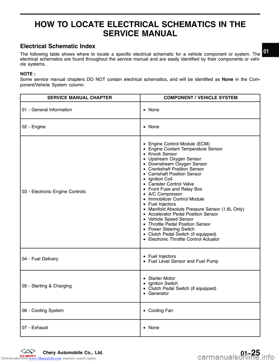
Electrical Schematic Index
The following table shows where to locate a specific electrical schematic for a vehicle component or system. The
electrical schematics are found throughout the service manual and are easily identified by their components or vehi-
cle systems.
NOTE :
Some service manual chapters DO NOT contain electrical schematics, and will be identified as Nonein the Com-
ponent/Vehicle System column.
SERVICE MANUAL CHAPTER COMPONENT / VEHICLE SYSTEM
01 - General Information •None
02 - Engine •None
03 - Electronic Engine Controls •
Engine Control Module (ECM)
• Engine Coolant Temperature Sensor
• Knock Sensor
• Upstream Oxygen Sensor
• Downstream Oxygen Sensor
• Crankshaft Position Sensor
• Camshaft Position Sensor
• Ignition Coil
• Canister Control Valve
• Front Fuse and Relay Box
• A/C Compressor
• Immobilizer Control Module
• Fuel Injectors
• Manifold Absolute Pressure Sensor (1.6L Only)
• Accelerator Pedal Position Sensor
• Vehicle Speed Sensor
• Throttle Pedal Position Sensor
• Power Steering Switch
• Clutch Pedal Switch (if equipped)
• Electronic Throttle Control Actuator
04 - Fuel Delivery •
Fuel Injectors
• Fuel Level Sensor and Fuel Pump
05 - Starting & Charging •
Starter Motor
• Ignition Switch
• Clutch Pedal Switch (if equipped)
• Generator
06 - Cooling System •Cooling Fan
07 - Exhaust •None
01
01–25Chery Automobile Co., Ltd.
Page 27 of 1903
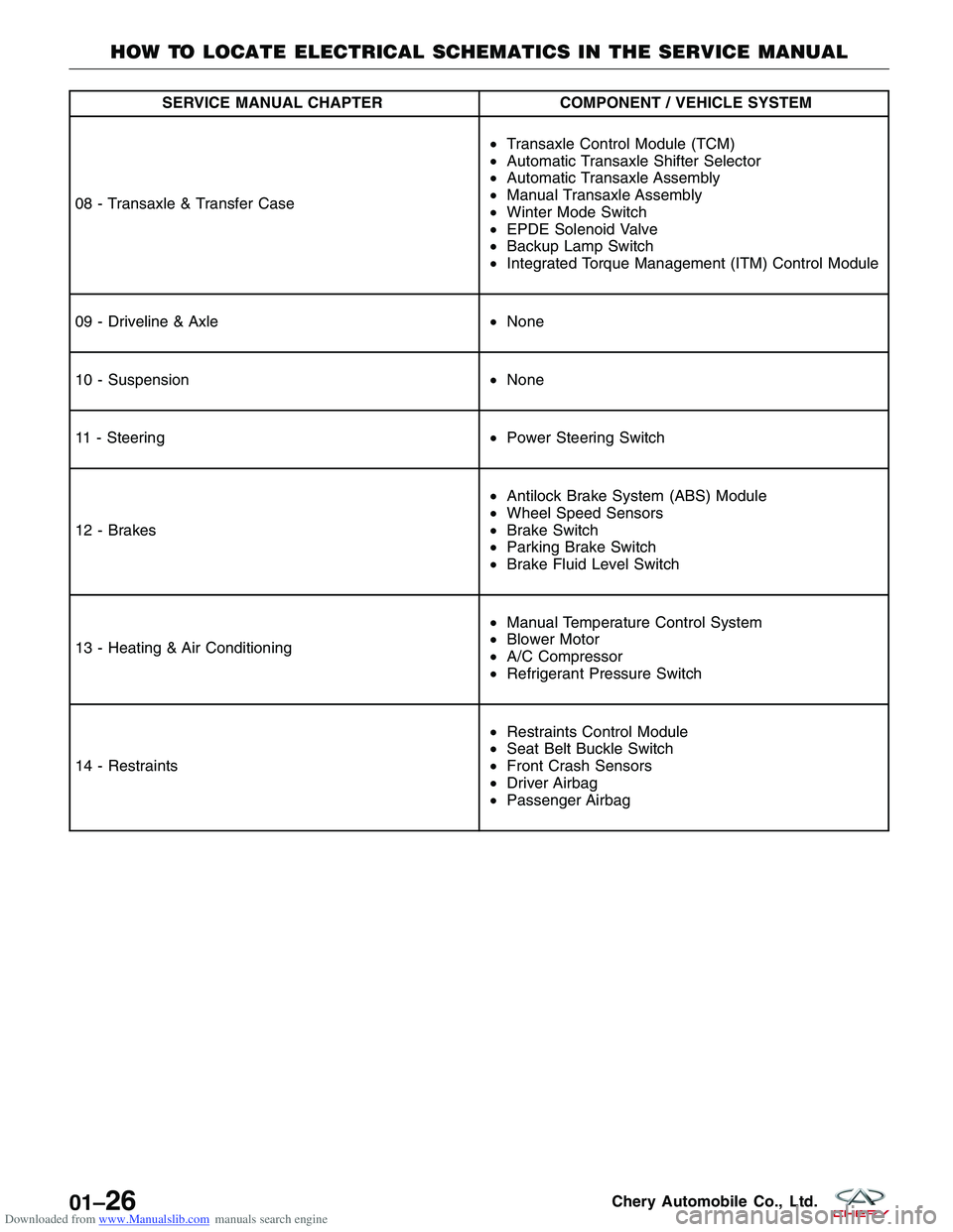
Downloaded from www.Manualslib.com manuals search engine SERVICE MANUAL CHAPTERCOMPONENT / VEHICLE SYSTEM
08 - Transaxle & Transfer Case •
Transaxle Control Module (TCM)
• Automatic Transaxle Shifter Selector
• Automatic Transaxle Assembly
• Manual Transaxle Assembly
• Winter Mode Switch
• EPDE Solenoid Valve
• Backup Lamp Switch
• Integrated Torque Management (ITM) Control Module
09 - Driveline & Axle •None
10 - Suspension •None
11 - Steering •Power Steering Switch
12 - Brakes •
Antilock Brake System (ABS) Module
• Wheel Speed Sensors
• Brake Switch
• Parking Brake Switch
• Brake Fluid Level Switch
13 - Heating & Air Conditioning •
Manual Temperature Control System
• Blower Motor
• A/C Compressor
• Refrigerant Pressure Switch
14 - Restraints •
Restraints Control Module
• Seat Belt Buckle Switch
• Front Crash Sensors
• Driver Airbag
• Passenger Airbag
HOW TO LOCATE ELECTRICAL SCHEMATICS IN THE SERVICE MANUAL
01–26Chery Automobile Co., Ltd.
Page 28 of 1903
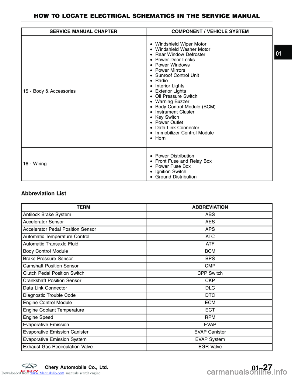
Downloaded from www.Manualslib.com manuals search engine SERVICE MANUAL CHAPTERCOMPONENT / VEHICLE SYSTEM
15 - Body & Accessories •
Windshield Wiper Motor
• Windshield Washer Motor
• Rear Window Defroster
• Power Door Locks
• Power Windows
• Power Mirrors
• Sunroof Control Unit
• Radio
• Interior Lights
• Exterior Lights
• Oil Pressure Switch
• Warning Buzzer
• Body Control Module (BCM)
• Instrument Cluster
• Key Switch
• Power Outlet
• Data Link Connector
• Immobilizer Control Module
• Horn
16 - Wiring •
Power Distribution
• Front Fuse and Relay Box
• Power Fuse Box
• Ignition Switch
• Ground Distribution
Abbreviation List
TERM ABBREVIATION
Antilock Brake System ABS
Accelerator Sensor AES
Accelerator Pedal Position Sensor APS
Automatic Temperature Control ATC
Automatic Transaxle Fluid ATF
Body Control Module BCM
Brake Pressure Sensor BPS
Camshaft Position Sensor CMP
Clutch Pedal Position Switch CPP Switch
Crankshaft Position Sensor CKP
Data Link Connector DLC
Diagnostic Trouble Code DTC
Engine Control Module ECM
Engine Coolant Temperature ECT
Engine Speed RPM
Evaporative Emission EVAP
Evaporative Emission Canister EVAP Canister
Evaporative Emission System EVAP System
Exhaust Gas Recirculation Valve EGR Valve
HOW TO LOCATE ELECTRICAL SCHEMATICS IN THE SERVICE MANUAL
01
01–27Chery Automobile Co., Ltd.
Page 29 of 1903
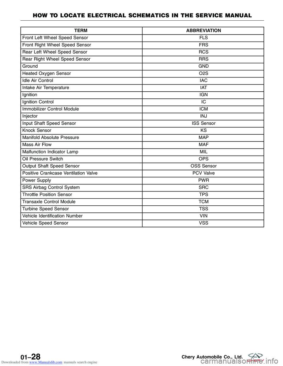
Downloaded from www.Manualslib.com manuals search engine TERMABBREVIATION
Front Left Wheel Speed Sensor FLS
Front Right Wheel Speed Sensor FRS
Rear Left Wheel Speed Sensor RCS
Rear Right Wheel Speed Sensor RRS
Ground GND
Heated Oxygen Sensor O2S
Idle Air Control IAC
Intake Air Temperature IAT
Ignition IGN
Ignition Control IC
Immobilizer Control Module ICM
Injector INJ
Input Shaft Speed Sensor ISS Sensor
Knock Sensor KS
Manifold Absolute Pressure MAP
Mass Air Flow MAF
Malfunction Indicator Lamp MIL
Oil Pressure Switch OPS
Output Shaft Speed Sensor OSS Sensor
Positive Crankcase Ventilation Valve PCV Valve
Power Supply PWR
SRS Airbag Control System SRC
Throttle Position Sensor TPS
Transaxle Control Module TCM
Turbine Speed Sensor TSS
Vehicle Identification Number VIN
Vehicle Speed Sensor VSS
HOW TO LOCATE ELECTRICAL SCHEMATICS IN THE SERVICE MANUAL
01–28Chery Automobile Co., Ltd.
Page 47 of 1903
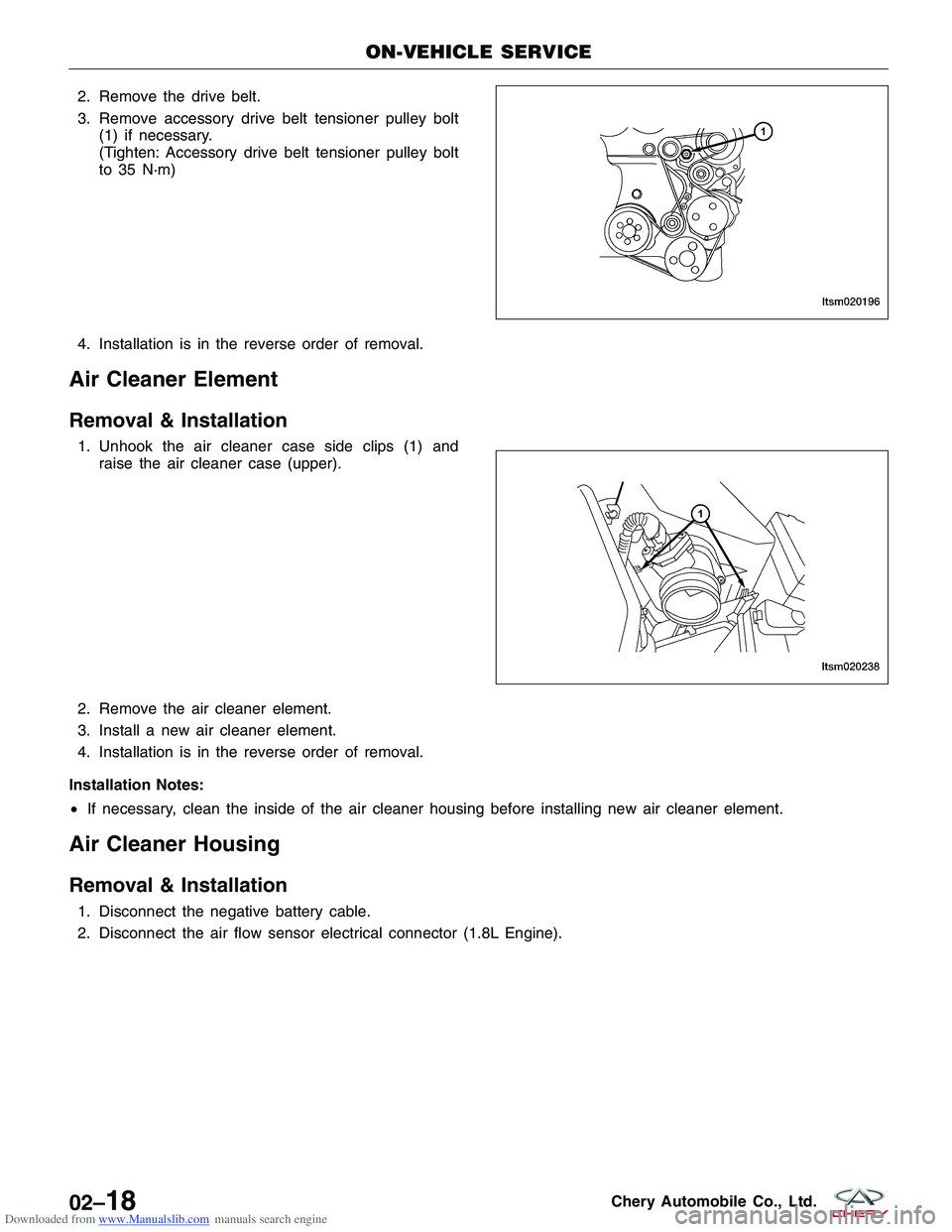
Downloaded from www.Manualslib.com manuals search engine 2. Remove the drive belt.
3. Remove accessory drive belt tensioner pulley bolt(1) if necessary.
(Tighten: Accessory drive belt tensioner pulley bolt
to 35 N·m)
4. Installation is in the reverse order of removal.
Air Cleaner Element
Removal & Installation
1. Unhook the air cleaner case side clips (1) and raise the air cleaner case (upper).
2. Remove the air cleaner element.
3. Install a new air cleaner element.
4. Installation is in the reverse order of removal.
Installation Notes:
• If necessary, clean the inside of the air cleaner housing before installing new air cleaner element.
Air Cleaner Housing
Removal & Installation
1. Disconnect the negative battery cable.
2. Disconnect the air flow sensor electrical connector (1.8L Engine).
ON-VEHICLE SERVICE
LTSM020196
LTSM020238
02–18Chery Automobile Co., Ltd.
Page 48 of 1903
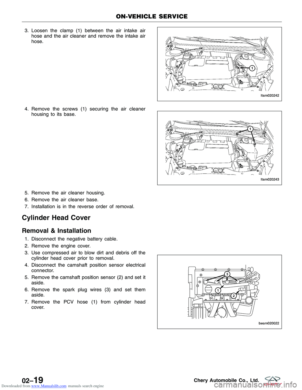
Downloaded from www.Manualslib.com manuals search engine 3. Loosen the clamp (1) between the air intake airhose and the air cleaner and remove the intake air
hose.
4. Remove the screws (1) securing the air cleaner housing to its base.
5. Remove the air cleaner housing.
6. Remove the air cleaner base.
7. Installation is in the reverse order of removal.
Cylinder Head Cover
Removal & Installation
1. Disconnect the negative battery cable.
2. Remove the engine cover.
3. Use compressed air to blow dirt and debris off the cylinder head cover prior to removal.
4. Disconnect the camshaft position sensor electrical connector.
5. Remove the camshaft position sensor (2) and set it aside.
6. Remove the spark plug wires (3) and set them aside.
7. Remove the PCV hose (1) from cylinder head cover.
ON-VEHICLE SERVICE
LTSM020242
LTSM020243
BESM020022
02–19Chery Automobile Co., Ltd.
Page 61 of 1903
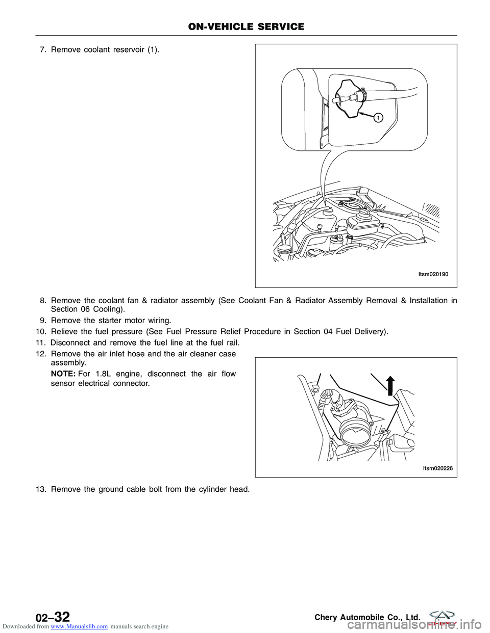
Downloaded from www.Manualslib.com manuals search engine 7. Remove coolant reservoir (1).
8. Remove the coolant fan & radiator assembly (See Coolant Fan & Radiator Assembly Removal & Installation inSection 06 Cooling).
9. Remove the starter motor wiring.
10. Relieve the fuel pressure (See Fuel Pressure Relief Procedure in Section 04 Fuel Delivery).
11. Disconnect and remove the fuel line at the fuel rail.
12. Remove the air inlet hose and the air cleaner case assembly.
NOTE: For 1.8L engine, disconnect the air flow
sensor electrical connector.
13. Remove the ground cable bolt from the cylinder head.
ON-VEHICLE SERVICE
LTSM020190
LTSM020226
02–32Chery Automobile Co., Ltd.
Page 62 of 1903
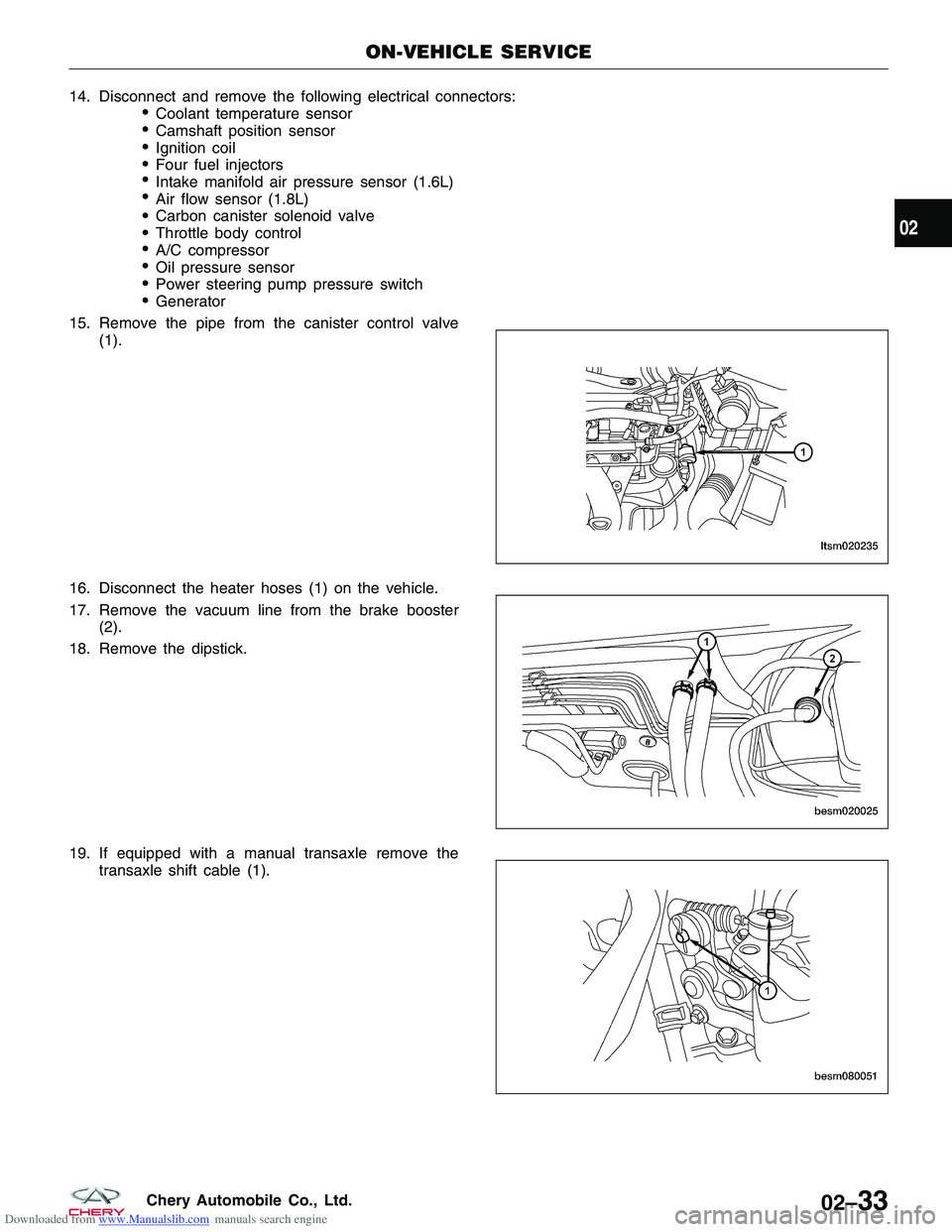
Downloaded from www.Manualslib.com manuals search engine 14.Disconnectandremovethefollowingelectricalconnectors:
€Coolanttemperaturesensor
€Camshaftpositionsensor
€Ignitioncoil
€Fourfuelinjectors
€Intakemanifoldairpressuresensor(1.6L)
€Airflowsensor(1.8L)
€Carboncanistersolenoidvalve
€Throttlebodycontrol
€A/Ccompressor
€Oilpressuresensor
€Powersteeringpumppressureswitch
€Generator
15.Removethepipefromthecanistercontrolvalve
(1).
16.Disconnecttheheaterhoses(1)onthevehicle.
17.Removethevacuumlinefromthebrakebooster
(2).
18.Removethedipstick.
19.Ifequippedwithamanualtransaxleremovethe
transaxleshiftcable(1).
ON-VEHICLESERVICE
LTSM020235
BESM020025
BESM080051
02
02–33CheryAutomobileCo.,Ltd.
Page 63 of 1903
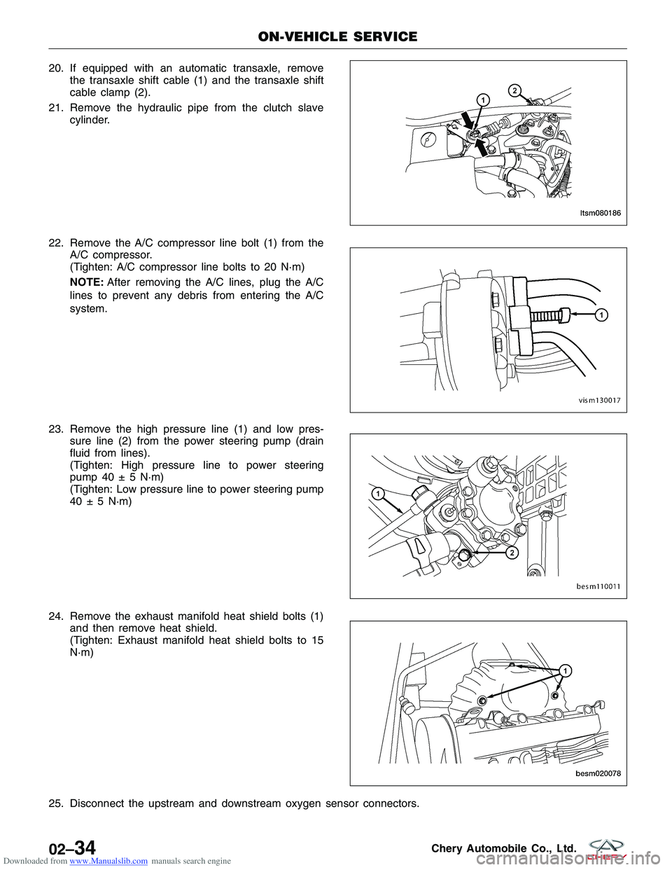
Downloaded from www.Manualslib.com manuals search engine 20. If equipped with an automatic transaxle, removethe transaxle shift cable (1) and the transaxle shift
cable clamp (2).
21. Remove the hydraulic pipe from the clutch slave cylinder.
22. Remove the A/C compressor line bolt (1) from the A/C compressor.
(Tighten: A/C compressor line bolts to 20 N·m)
NOTE: After removing the A/C lines, plug the A/C
lines to prevent any debris from entering the A/C
system.
23. Remove the high pressure line (1) and low pres- sure line (2) from the power steering pump (drain
fluid from lines).
(Tighten: High pressure line to power steering
pump 40 ± 5 N·m)
(Tighten: Low pressure line to power steering pump
40 ± 5 N·m)
24. Remove the exhaust manifold heat shield bolts (1) and then remove heat shield.
(Tighten: Exhaust manifold heat shield bolts to 15
N·m)
25. Disconnect the upstream and downstream oxygen sensor connectors.
ON-VEHICLE SERVICE
LTSM080186
VISM130017
BESM110011
BESM020078
02–34Chery Automobile Co., Ltd.