drain bolt CHERY TIGGO 2009 Service User Guide
[x] Cancel search | Manufacturer: CHERY, Model Year: 2009, Model line: TIGGO, Model: CHERY TIGGO 2009Pages: 1903, PDF Size: 33.38 MB
Page 146 of 1903
Downloaded from www.Manualslib.com manuals search engine Installation Notes:
•Clean all surfaces of manifold and cylinder head.
• Install a new exhaust manifold gasket during installation.
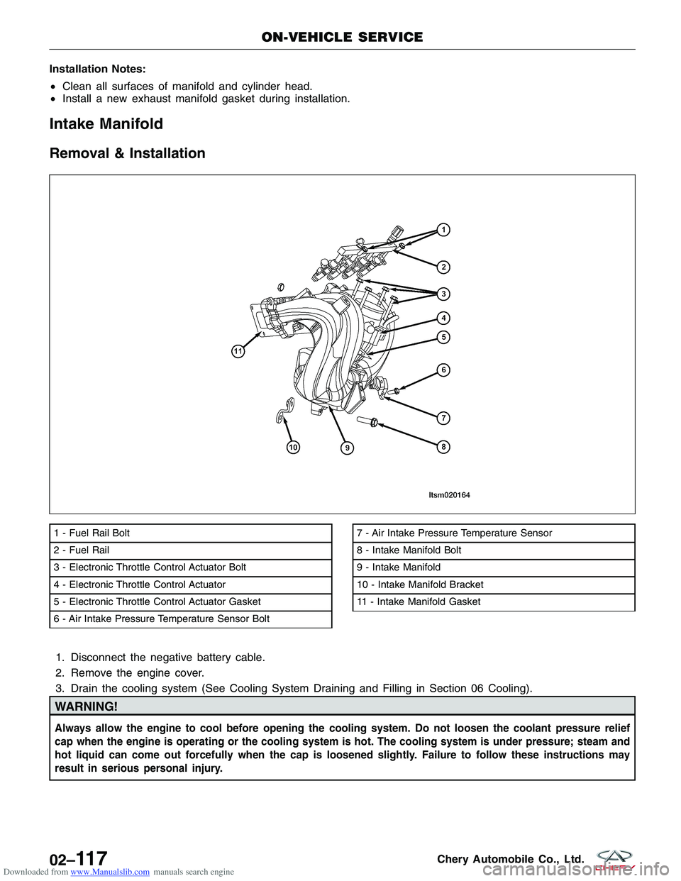
Intake Manifold
Removal & Installation
1. Disconnect the negative battery cable.
2. Remove the engine cover.
3. Drain the cooling system (See Cooling System Draining and Filling in Section 06 Cooling).
WARNING!
Always allow the engine to cool before opening the cooling system. Do not loosen the coolant pressure relief
cap when the engine is operating or the cooling system is hot. The cooling system is under pressure; steam and
hot liquid can come out forcefully when the cap is loosened slightly. Failure to follow these instructions may
result in serious personal injury.
1 - Fuel Rail Bolt
2 - Fuel Rail
3 - Electronic Throttle Control Actuator Bolt
4 - Electronic Throttle Control Actuator
5 - Electronic Throttle Control Actuator Gasket
6 - Air Intake Pressure Temperature Sensor Bolt7 - Air Intake Pressure Temperature Sensor
8 - Intake Manifold Bolt
9 - Intake Manifold
10 - Intake Manifold Bracket
11 - Intake Manifold Gasket
ON-VEHICLE SERVICE
LTSM020164
02–11 7Chery Automobile Co., Ltd.
Page 149 of 1903
Downloaded from www.Manualslib.com manuals search engine WARNING!
Prolonged and repeated contact with engine oil will harm your skin. If engine oil is spilled on your skin, wash it
off immediately with water. In addition, used engine oil contains potentially harmful contaminants which may
cause skin cancer. Always use adequate skin protection when performing vehicle service.
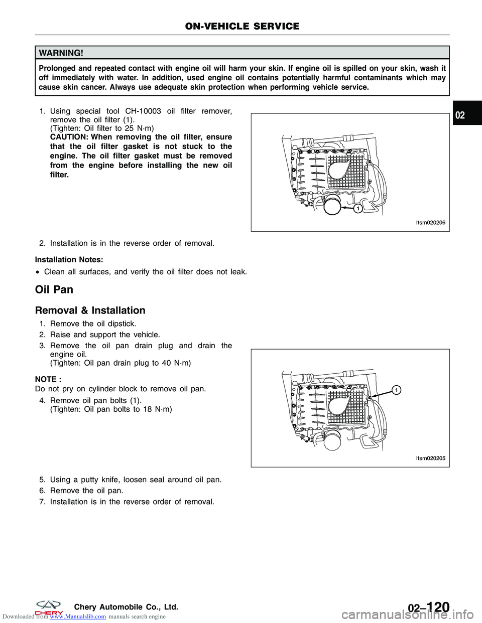
1. Using special tool CH-10003 oil filter remover,remove the oil filter (1).
(Tighten: Oil filter to 25 N·m)
CAUTION: When removing the oil filter, ensure
that the oil filter gasket is not stuck to the
engine. The oil filter gasket must be removed
from the engine before installing the new oil
filter.
2. Installation is in the reverse order of removal.
Installation Notes:
• Clean all surfaces, and verify the oil filter does not leak.
Oil Pan
Removal & Installation
1. Remove the oil dipstick.
2. Raise and support the vehicle.
3. Remove the oil pan drain plug and drain the
engine oil.
(Tighten: Oil pan drain plug to 40 N·m)
NOTE :
Do not pry on cylinder block to remove oil pan. 4. Remove oil pan bolts (1). (Tighten: Oil pan bolts to 18 N·m)
5. Using a putty knife, loosen seal around oil pan.
6. Remove the oil pan.
7. Installation is in the reverse order of removal.
ON-VEHICLE SERVICE
LTSM020206
LTSM020205
02
02–120Chery Automobile Co., Ltd.
Page 183 of 1903
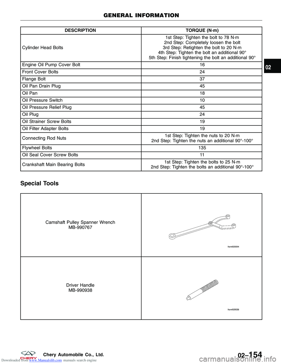
Downloaded from www.Manualslib.com manuals search engine DESCRIPTIONTORQUE (N·m)
Cylinder Head Bolts 1st Step: Tighten the bolt to 78 N·m
2nd Step: Completely loosen the bolt
3rd Step: Retighten the bolt to 20 N·m
4th Step: Tighten the bolt an additional 90°
5th Step: Finish tightening the bolt an additional 90°
Engine Oil Pump Cover Bolt 16
Front Cover Bolts 24
Flange Bolt 37
Oil Pan Drain Plug 45
Oil Pan 18
Oil Pressure Switch 10
Oil Pressure Relief Plug 45
Oil Plug 24
Oil Strainer Screw Bolts 19
Oil Filter Adapter Bolts 19
Connecting Rod Nuts 1st Step: Tighten the nuts to 20 N·m
2nd Step: Tighten the nuts an additional 90°-100°
Flywheel Bolts 135
Oil Seal Cover Screw Bolts 11
Crankshaft Main Bearing Bolts 1st Step: Tighten the bolts to 25 N·m
2nd Step: Tighten the bolts an additional 90°-100°
Special Tools
Camshaft Pulley Spanner Wrench MB-990767
Driver HandleMB-990938
GENERAL INFORMATION
02
02–154Chery Automobile Co., Ltd.
Page 204 of 1903

Downloaded from www.Manualslib.com manuals search engine Cylinder Head
Removal & Installation
1. Drain the cooling system (See Cooling System Draining and Filling in Section 06 Cooling).
2. Remove the engine timing belt (See Engine Timing Belt Removal & Installation in Section 02 Engine).
3. Remove the cylinder head cover (See Cylinder Head Cover Removal & Installation in Section 02 Engine).
4. Remove the camshafts (See Camshaft Removal & Installation in Section 02 Engine).
5. Remove the intake manifold (See Intake Manifold Removal & Installation in Section 02 Engine).
6. Remove the exhaust manifold (See Exhaust Manifold Removal & Installation in Section 02 Engine).
7. Remove the water pipe and thermostat assembly.
1 - Cylinder Head Bolt
2 - Valve Spring Locks
3 - Upper Valve Spring Retainer
4 - Valve Spring
5 - Valve Oil Seal6 - Lower Valve Spring Retainer
7 - Valve Guide
8 - Valve Seat
9 - Valve
10 - Cylinder Head
ON-VEHICLE SERVICE
LTSM020090
02
02–175Chery Automobile Co., Ltd.
Page 212 of 1903
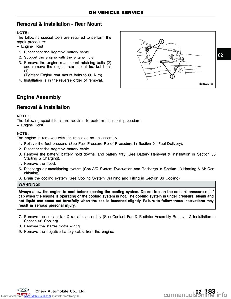
Downloaded from www.Manualslib.com manuals search engine Removal & Installation - Rear Mount
NOTE :
The following special tools are required to perform the
repair procedure:
•Engine Hoist
1. Disconnect the negative battery cable.
2. Support the engine with the engine hoist.
3. Remove the engine rear mount retaining bolts (2) and remove the engine rear mount bracket bolts
(1).
(Tighten: Engine rear mount bolts to 60 N·m)
4. Installation is in the reverse order of removal.
Engine Assembly
Removal & Installation
NOTE :
The following special tools are required to perform the repair procedure:
• Engine Hoist
NOTE :
The engine is removed with the transaxle as an assembly. 1. Relieve the fuel pressure (See Fuel Pressure Relief Procedure in Section 04 Fuel Delivery).
2. Disconnect the negative battery cable.
3. Remove the battery, battery hold downs, and battery tray (See Battery Removal & Installation in Section 05 Starting & Charging).
4. Remove the hood.
5. Discharge air conditioning system (See A/C System Evacuation and Recharge in Section 13 Heating & Air Con- ditioning).
6. Drain the cooling system (See Cooling System Draining and Filling in Section 06 Cooling).
WARNING!
Always allow the engine to cool before opening the cooling system. Do not loosen the coolant pressure relief
cap when the engine is operating or the cooling system is hot. The cooling system is under pressure; steam and
hot liquid can come out forcefully when the cap is loosened slightly. Failure to follow these instructions may
result in serious personal injury.
7. Remove the coolant fan & radiator assembly (See Coolant Fan & Radiator Assembly Removal & Installation in Section 06 Cooling).
8. Remove the starter motor wiring.
9. Remove the negative battery cable from the engine.
ON-VEHICLE SERVICE
LTSM020188
02
02–183Chery Automobile Co., Ltd.
Page 215 of 1903
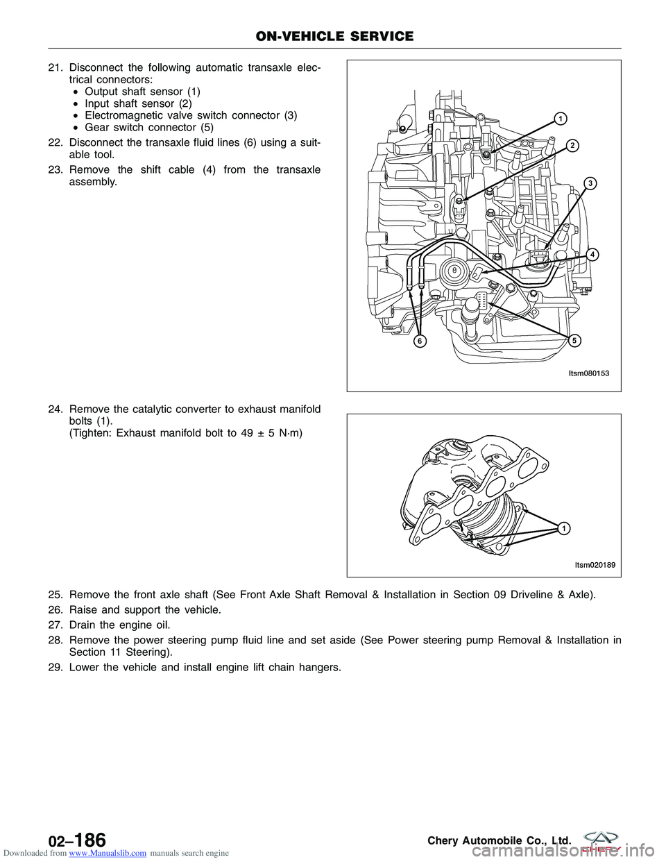
Downloaded from www.Manualslib.com manuals search engine 21. Disconnect the following automatic transaxle elec-trical connectors:• Output shaft sensor (1)
• Input shaft sensor (2)
• Electromagnetic valve switch connector (3)
• Gear switch connector (5)
22. Disconnect the transaxle fluid lines (6) using a suit- able tool.
23. Remove the shift cable (4) from the transaxle assembly.
24. Remove the catalytic converter to exhaust manifold bolts (1).
(Tighten: Exhaust manifold bolt to 49 ± 5 N·m)
25. Remove the front axle shaft (See Front Axle Shaft Removal & Installation in Section 09 Driveline & Axle).
26. Raise and support the vehicle.
27. Drain the engine oil.
28. Remove the power steering pump fluid line and set aside (See Power steering pump Removal & Installation in Section 11 Steering).
29. Lower the vehicle and install engine lift chain hangers.
ON-VEHICLE SERVICE
LTSM080153
LTSM020189
02–186Chery Automobile Co., Ltd.
Page 219 of 1903

Downloaded from www.Manualslib.com manuals search engine NOTE :
The following special tools are required to perform the repair procedure:
•MB-990767 - Timing Belt Spanner Wrench
• MD-998785 - Timing Belt Gear Holder
• MD-998767 - Automatic Tensioner Socket
1. Drain the cooling system (See Cooling System Draining and Filling in Section 06 Cooling).
WARNING!
Always allow the engine to cool before opening the cooling system. Do not loosen the coolant pressure relief
cap when the engine is operating or the cooling system is hot. The cooling system is under pressure; steam and
hot liquid can come out forcefully when the cap is loosened slightly. Failure to follow these instructions may
result in serious personal injury.
2. Attach an engine hoist to the engine.
3. Raise the engine with the engine hoist, just enough to support the engine.
1 - Right Engine Mounting Bracket
2 - Spacer
3 - Upper Balance Shaft Pulley
4 - Upper Balance Shaft Timing Belt
5 - Upper Balance Shaft Timing Belt Tensioner
6 - Crankshaft Sensing Blade
7 - Upper Timing Belt Cover
8 - Lower Timing Belt Cover
9 - Timing Belt Automatic Tensioner
10 - Idler Pulley
11 - Crankshaft Bolt12 - Crankshaft Timing Belt Pulley
13 - Lower Balance Shaft Pulley
14 - Crankshaft Position Sensor
15 - Power Steering Bracket
16 - Timing Belt Rear Cover
17 - Timing Belt
18 - Camshaft Timing Pulley
19 - Camshaft Pulley Bolt
20 - Crankshaft Upper Balance Shaft Pulley
21 - Tensioner Arm
22 - Tensioner Pulley
ON-VEHICLE SERVICE
LTSM020048
02–190Chery Automobile Co., Ltd.
Page 234 of 1903
Downloaded from www.Manualslib.com manuals search engine NOTE :
The following special tools are required to perform the repair procedure:
•MB-991603 - Balance Shaft Bearing Puller Limiter
• MD-998162 - Plug Spanner
• MD-998371 - Balance Shaft Bearing Puller
• MD-998372 - Balance Shaft Bearing Puller
• MD-998375 - Crankshaft Front Oil Seal Installer
• MD-998705 - Balance Shaft Bearing Installer
• MD-998727 - Oil Pan Remover
• MD-998783 - Plug Spanner Fixer
• MB-991828 - Oil Filter Wrench
• MB-991396 - Oil Filter Wrench
1. Remove the engine timing belt (See Engine Timing Belt Removal & Installation in Section 02 Engine).
2. Remove the upper balance shaft timing belt (See Upper Balance Shaft Timing Belt Removal & Installation in Section 02 Engine).
3. Raise and support the vehicle.
4. Loosen the oil drain plug and drain the oil.
5. Remove the oil pan retaining bolts. (Tighten: Oil pan bolts to 18 N·m)
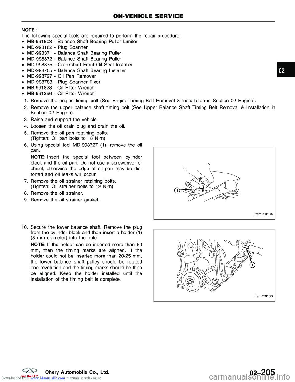
6. Using special tool MD-998727 (1), remove the oil pan.
NOTE: Insert the special tool between cylinder
block and the oil pan. Do not use a screwdriver or
chisel, otherwise the edge of oil pan may be dis-
torted and oil leaks will occur.
7. Remove the oil strainer retaining bolts. (Tighten: Oil strainer bolts to 19 N·m)
8. Remove the oil strainer.
9. Remove the oil strainer gasket.
10. Secure the lower balance shaft. Remove the plug from the cylinder block and then insert a holder (1)
(8 mm diameter) into the hole.
NOTE: If the holder can be inserted more than 60
mm, then the timing marks are aligned. If the
holder could not be inserted more than 20-25 mm,
the lower balance shaft pulley should be rotated
one revolution and the timing marks should be then
be aligned. Keep the holder installed until the
installation of the timing belt is complete.
ON-VEHICLE SERVICE
LTSM020134
LTSM020186
02
02–205Chery Automobile Co., Ltd.
Page 238 of 1903
Downloaded from www.Manualslib.com manuals search engine NOTE :
The following special tools are required to perform the repair procedure:
•MD-991603 - Balance Shaft Bearing Puller Limiter
• MD-998162 - Plug Spanner
• MD-998371 - Balance Shaft Bearing Puller
• MD-998372 - Balance Shaft Bearing Puller
• MD-998375 - Crankshaft Front Oil Seal Installer
• MD-998705 - Balance Shaft Bearing Installer
• MD-998727 - Oil Pan Remover
• MD-998783 - Plug Spanner Fixer
• MD-991828 - Oil Filter Wrench
• MD-991396 - Oil Filter Wrench
1. Raise and support the vehicle.
2. Loosen the oil drain plug and drain the oil.
3. Remove the engine timing belt (See Engine Timing Belt Removal & Installation in Section 02 Engine).
4. Remove the upper balance shaft timing belt (See Upper Balance Shaft Timing Belt Removal & Installation in Section 02 Engine).
5. Remove the oil pan retaining bolts. (Tighten: Oil pan bolts to 18 N·m)
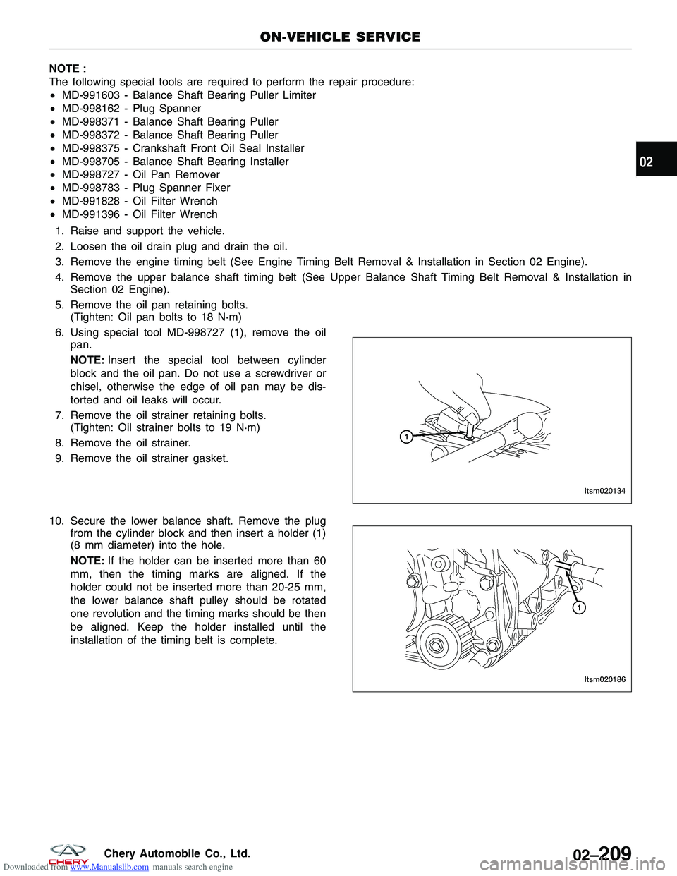
6. Using special tool MD-998727 (1), remove the oil pan.
NOTE: Insert the special tool between cylinder
block and the oil pan. Do not use a screwdriver or
chisel, otherwise the edge of oil pan may be dis-
torted and oil leaks will occur.
7. Remove the oil strainer retaining bolts. (Tighten: Oil strainer bolts to 19 N·m)
8. Remove the oil strainer.
9. Remove the oil strainer gasket.
10. Secure the lower balance shaft. Remove the plug from the cylinder block and then insert a holder (1)
(8 mm diameter) into the hole.
NOTE: If the holder can be inserted more than 60
mm, then the timing marks are aligned. If the
holder could not be inserted more than 20-25 mm,
the lower balance shaft pulley should be rotated
one revolution and the timing marks should be then
be aligned. Keep the holder installed until the
installation of the timing belt is complete.
ON-VEHICLE SERVICE
LTSM020134
LTSM020186
02
02–209Chery Automobile Co., Ltd.
Page 242 of 1903
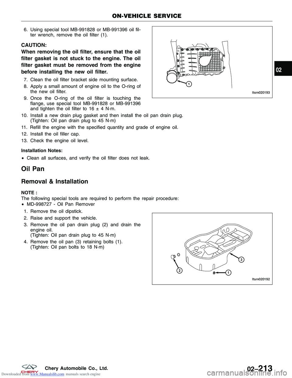
Downloaded from www.Manualslib.com manuals search engine 6. Using special tool MB-991828 or MB-991396 oil fil-ter wrench, remove the oil filter (1).
CAUTION:
When removing the oil filter, ensure that the oil
filter gasket is not stuck to the engine. The oil
filter gasket must be removed from the engine
before installing the new oil filter.
7. Clean the oil filter bracket side mounting surface.
8. Apply a small amount of engine oil to the O-ring ofthe new oil filter.
9. Once the O-ring of the oil filter is touching the flange, use special tool MB-991828 or MB-991396
and tighten the oil filter to 16 ± 4 N·m.
10. Install a new drain plug gasket and then install the oil pan drain plug. (Tighten: Oil pan drain plug to 45 N·m)
11. Refill the engine with the specified quantity and grade of engine oil.
12. Install the oil filler cap.
13. Check the engine oil level.
Installation Notes:
• Clean all surfaces, and verify the oil filter does not leak.
Oil Pan
Removal & Installation
NOTE :
The following special tools are required to perform the repair procedure:
•MD-998727 - Oil Pan Remover
1. Remove the oil dipstick.
2. Raise and support the vehicle.
3. Remove the oil pan drain plug (2) and drain the engine oil.
(Tighten: Oil pan drain plug to 45 N·m)
4. Remove the oil pan (3) retaining bolts (1). (Tighten: Oil pan bolts to 18 N·m)
ON-VEHICLE SERVICE
LTSM020193
LTSM020192
02
02–213Chery Automobile Co., Ltd.