dimensions CHERY TIGGO 2009 Service Repair Manual
[x] Cancel search | Manufacturer: CHERY, Model Year: 2009, Model line: TIGGO, Model: CHERY TIGGO 2009Pages: 1903, PDF Size: 33.38 MB
Page 255 of 1903

Downloaded from www.Manualslib.com manuals search engine •Check the inner diameter of connecting rod (small end).
PISTON PIN CLEARANCE
Piston and Piston Pin 0.002 - 0.013 mm
Assembly
Piston Pin Installation
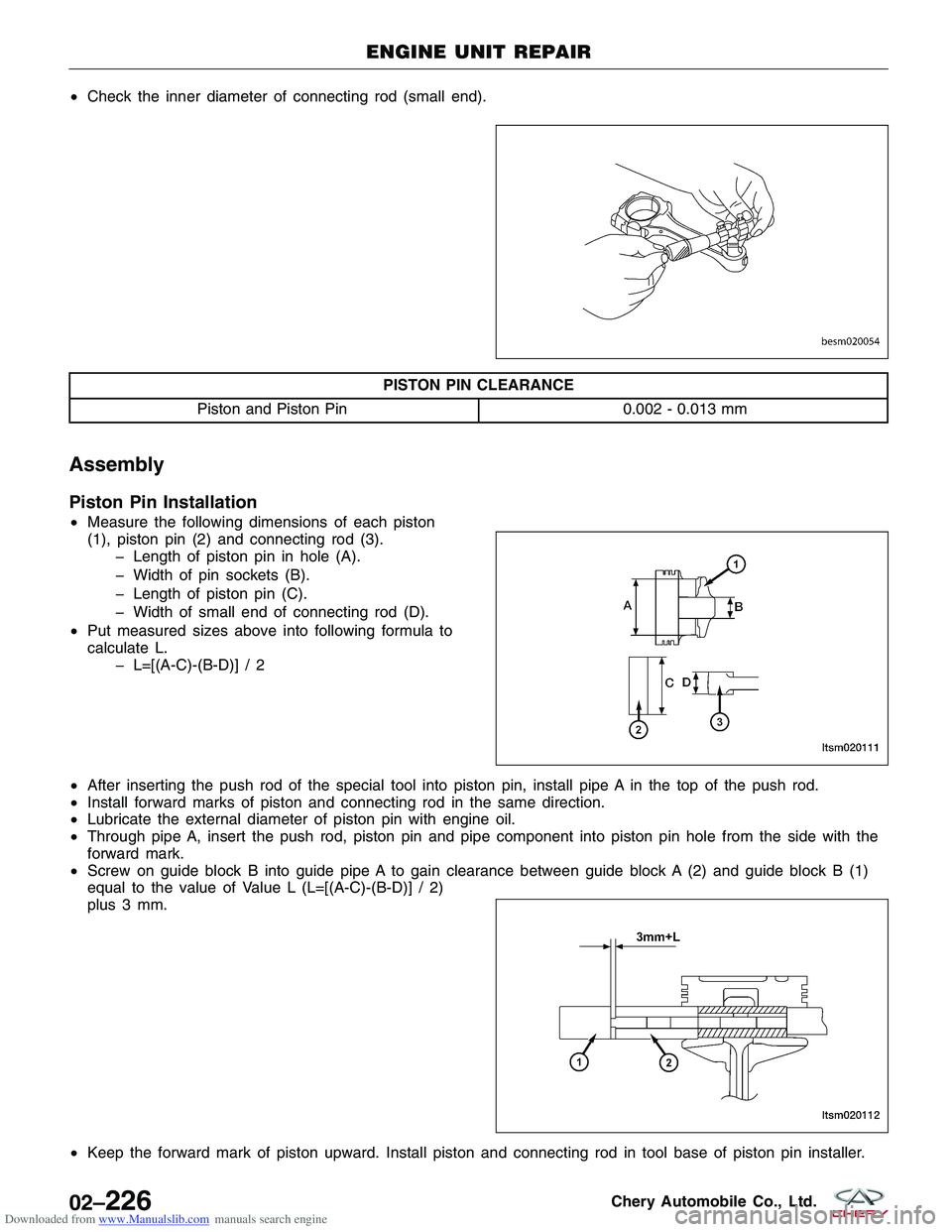
•Measure the following dimensions of each piston
(1), piston pin (2) and connecting rod (3).
� Length of piston pin in hole (A).
� Width of pin sockets (B).
� Length of piston pin (C).
� Width of small end of connecting rod (D).
• Put measured sizes above into following formula to
calculate L.
� L=[(A-C)-(B-D)] / 2
• After inserting the push rod of the special tool into piston pin, install pipe A in the top of the push rod.
• Install forward marks of piston and connecting rod in the same direction.
• Lubricate the external diameter of piston pin with engine oil.
• Through pipe A, insert the push rod, piston pin and pipe component into piston pin hole from the side with the
forward mark.
• Screw on guide block B into guide pipe A to gain clearance between guide block A (2) and guide block B (1)
equal to the value of Value L (L=[(A-C)-(B-D)] / 2)
plus 3 mm.
• Keep the forward mark of piston upward. Install piston and connecting rod in tool base of piston pin installer.
ENGINE UNIT REPAIR
BESM020054
LTSM020111
LTSM020112
02–226Chery Automobile Co., Ltd.
Page 906 of 1903

Downloaded from www.Manualslib.com manuals search engine Battery Tray
Removal & Installation
1. Disconnect the negative battery cable.
2. Disconnect the positive battery cable.
3. Remove the battery hold down.
4. Remove the battery.
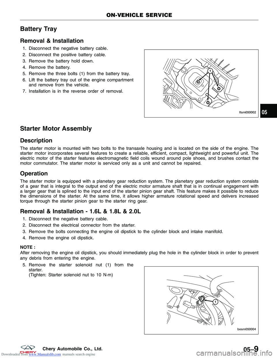
5. Remove the three bolts (1) from the battery tray.
6. Lift the battery tray out of the engine compartmentand remove from the vehicle.
7. Installation is in the reverse order of removal.
Starter Motor Assembly
Description
The starter motor is mounted with two bolts to the transaxle housing and is located on the side of the engine. The
starter motor incorporates several features to create a reliable, efficient, compact, lightweight and powerful unit. The
electric motor of the starter features electromagnetic field coils wound around pole shoes, and brushes contact the
motor commutator. The starter motor is serviced only as a unit and cannot be repaired.
Operation
The starter motor is equipped with a planetary gear reduction system. The planetary gear reduction system consists
of a gear that is integral to the output end of the electric motor armature shaft that is in continual engagement with
a larger gear that is splined to the input end of the starter pinion gear shaft. This feature makes it possible to reduce
the dimensions of the starter. At the same time, it allows higher armature rotational speed and delivers increased
torque through the starter pinion gear to the starter ring gear.
Removal & Installation - 1.6L & 1.8L & 2.0L
1. Disconnect the negative battery cable.
2. Disconnect the electrical connector from the starter.
3. Remove the bolts connecting the engine oil dipstick to the cylinder block and intake manifold.
4. Remove the engine oil dipstick.
NOTE :
After removing the engine oil dipstick, you should immediately plug the hole in the cylinder block in order to prevent
any debris from entering the engine. 5. Remove the starter solenoid nut (1) from the starter.
(Tighten: Starter solenoid nut to 10 N·m)
ON-VEHICLE SERVICE
LTSM050002
BESM050004
05
05–9Chery Automobile Co., Ltd.
Page 1729 of 1903

Downloaded from www.Manualslib.com manuals search engine BODY EXTERIOR
BODY DIMENSIONS15-147
Description 15-147
Front Body Structure 15-148
Dimension of Engine Compartment
(Units: mm) 15-148
Front Structure 15-151
Dimension of Front Structure (Units:
mm) 15-151
Frame 15-153
Body Frame Dimensions (Units: mm) 15-153
Vehicle Clearance 15-154
Front View 15-154
Body 15-157
Side View 15-157
BUMPERS15-166
Front Bumper 15-166
Removal & Installation 15-166
DOORS15-167
Specification 15-167
Front Door 15-168
Removal & Installation 15-168
Disassembly 15-168
Assembly 15-172
Front Door Adjustment 15-172
Replacing Front Door Hinge 15-172
Rear Door 15-173
Removal & Installation 15-173
Disassembly 15-173
Assembly 15-174
Rear Door Adjustment 15-174
Replacing Rear Door Hinge 15-175
Back Cargo Door 15-175
Removal & Installation 15-175
Disassembly 15-175
Assembly 15-177
Back Cargo Door Adjustment 15-177
Replacing Rear Door Hinge 15-177
EXTERIOR LAMPS15-178
Description 15-178
Operation 15-178
Specification 15-178
Electrical Schematics 15-179
Front Combination Lamp Assembly 15-189
Removal & Installation 15-189
Headlamp Adjustment Procedure 15-190
Rear Combination Lamp Assembly 15-190
Removal & Installation 15-190Headlamp
15-191
Removal & Installation 15-191
Front Fog Lamp 15-192
Removal & Installation 15-192
Rear Fog Lamp 15-193
Removal & Installation 15-193
Tail/Backup/Stop Lamp 15-194
Removal & Installation 15-194
Turn Signal Lamp 15-195
Removal & Installation 15-195
High Mounted Stop Lamp 15-197
Removal & Installation 15-197
License Plate Lamp 15-197
Removal & Installation 15-197
FENDER15-199
Front Fender 15-199
Removal & Installation 15-199
FUEL DOOR15-200
Fuel Door 15-200
Removal & Installation 15-200
GRILLE15-201
Grille 15-201
Removal & Installation 15-201
HOOD15-202
Hood 15-202
Removal & Installation 15-202
Hood Adjustment 15-202
Hood Release Cable 15-203
Removal & Installation 15-203
LUGGAGE RACK15-204
Luggage Rack 15-204
Removal & Installation 15-204
SPARE TIRE SUPPORT15-205
Spare Tire Support 15-205
Removal & Installation 15-205
HORN15-206
Description 15-206
Operation 15-206
Electrical Schematics 15-207
Horn 15-208
Removal & Installation 15-208
15
15–145Chery Automobile Co., Ltd.
Page 1731 of 1903

Downloaded from www.Manualslib.com manuals search engine BODY DIMENSIONS
Description
•All measurements should be made from the bare metal, remove trim and bumper covers as necessary.
• Repair the badly damaged areas before taking measurements for underbody alignment.
• Monitor the upper body structure for excessive stress or movement while making any corrections to the under-
body structure.
• Remove all the necessary glass to prevent breakage.
• All dimensions are shown in millimeters (mm).
15
15–147Chery Automobile Co., Ltd.
Page 1732 of 1903

Downloaded from www.Manualslib.com manuals search engine Front Body Structure
Dimension of Engine Compartment (Units: mm)
BODY DIMENSIONS
LTSM150032
15–148Chery Automobile Co., Ltd.
Page 1733 of 1903

Downloaded from www.Manualslib.com manuals search engine Dimension of Body Openings
Dimension of body, Left-Right.
Uppercase letters indicate the right side of the body, lowercase letters indicate the left side of the body (Rear view).
BODY DIMENSIONS
LTSM150002
15
15–149Chery Automobile Co., Ltd.
Page 1734 of 1903

Downloaded from www.Manualslib.com manuals search engine BODY DIMENSIONS
LTSM150003
15–150Chery Automobile Co., Ltd.
Page 1735 of 1903

Downloaded from www.Manualslib.com manuals search engine Front Structure
Dimension of Front Structure (Units: mm)
Body dimension, Left-Right
BODY DIMENSIONS
LTSM150001
15
15–151Chery Automobile Co., Ltd.
Page 1736 of 1903

Downloaded from www.Manualslib.com manuals search engine NOTE :
Uppercase letters indicate the left side of the body. Lowercase letters indicate the right side of the body (view from
the rear of the vehicle).
S/NCONTROL
DIMENSION (mm) DESCRIPTION
AB=PQ 1485.8 Diagonal distance
of front windshield
CD 733.2Distance of front
windshield at Y0
IJ 1491.6Center distance
between the right
end of upper
cover of the lower
beam of front
windshield and
the installation
hole of front
fender
EH 736.1Center distance
between the
upper cover hole
of the lower beam
of front windshield
and the
installation hole of
front fenderS/N
CONTROL
DIMENSION (mm) DESCRIPTION
FH 270.7 Center distance
between the hole
of front shock
absorber and the
installation hole of
front fender
FG 1126.8Center distance
between the holes
of left/right front
shock absorber
LM 952.8Center distance
between the holes
of left/right engine
suspension
KE 690.5Center distance
between the
upper cover hole
of front windshield
beam and the
installation hole of
radiator
BODY DIMENSIONS
LTSM150001
15–152Chery Automobile Co., Ltd.
Page 1737 of 1903

Downloaded from www.Manualslib.com manuals search engine Frame
Body Frame Dimensions (Units: mm)
BODY DIMENSIONS
LTSM150004
15
15–153Chery Automobile Co., Ltd.