engine coolant CHERY TIGGO 2009 Service User Guide
[x] Cancel search | Manufacturer: CHERY, Model Year: 2009, Model line: TIGGO, Model: CHERY TIGGO 2009Pages: 1903, PDF Size: 33.38 MB
Page 68 of 1903
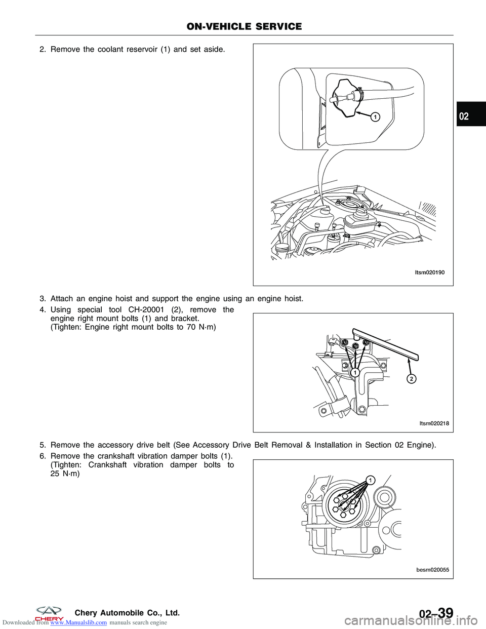
Downloaded from www.Manualslib.com manuals search engine 2. Remove the coolant reservoir (1) and set aside.
3. Attach an engine hoist and support the engine using an engine hoist.
4. Using special tool CH-20001 (2), remove theengine right mount bolts (1) and bracket.
(Tighten: Engine right mount bolts to 70 N·m)
5. Remove the accessory drive belt (See Accessory Drive Belt Removal & Installation in Section 02 Engine).
6. Remove the crankshaft vibration damper bolts (1). (Tighten: Crankshaft vibration damper bolts to
25 N·m)
ON-VEHICLE SERVICE
LTSM020190
LTSM020218
BESM020055
02
02–39Chery Automobile Co., Ltd.
Page 72 of 1903
Downloaded from www.Manualslib.com manuals search engine Installation Notes:
•Clean all surfaces of manifold and cylinder head.
• Install a new exhaust manifold gasket during installation.
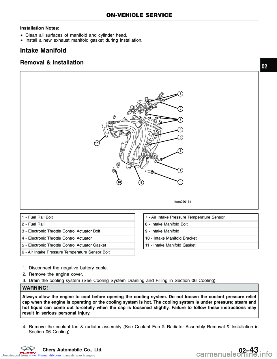
Intake Manifold
Removal & Installation
1. Disconnect the negative battery cable.
2. Remove the engine cover.
3. Drain the cooling system (See Cooling System Draining and Filling in Section 06 Cooling).
WARNING!
Always allow the engine to cool before opening the cooling system. Do not loosen the coolant pressure relief
cap when the engine is operating or the cooling system is hot. The cooling system is under pressure; steam and
hot liquid can come out forcefully when the cap is loosened slightly. Failure to follow these instructions may
result in serious personal injury.
4. Remove the coolant fan & radiator assembly (See Coolant Fan & Radiator Assembly Removal & Installation in
Section 06 Cooling).
1 - Fuel Rail Bolt
2 - Fuel Rail
3 - Electronic Throttle Control Actuator Bolt
4 - Electronic Throttle Control Actuator
5 - Electronic Throttle Control Actuator Gasket
6 - Air Intake Pressure Temperature Sensor Bolt7 - Air Intake Pressure Temperature Sensor
8 - Intake Manifold Bolt
9 - Intake Manifold
10 - Intake Manifold Bracket
11 - Intake Manifold Gasket
ON-VEHICLE SERVICE
LTSM020164
02
02–43Chery Automobile Co., Ltd.
Page 81 of 1903
Downloaded from www.Manualslib.com manuals search engine 8. Installation is in the reverse order of removal.
Inspection
NOTE :
All measurements should be taken with the engine block at room temperature, 21°C.
Engine Block
•Clean cylinder block thoroughly and check all core hole plugs for evidence of leaking.
• Examine block and cylinder bores for cracks or fractures.
• Check block deck surfaces for flatness. Deck surface must be within service limit of 0.050 mm.
Cylinder Bore
• The cylinder walls should be checked for out-of-round and taper with cylinder indicator or equivalent. If the cyl-
inder walls are badly scuffed or scored, the cylinder block should be replaced, and new pistons and rings fitted.
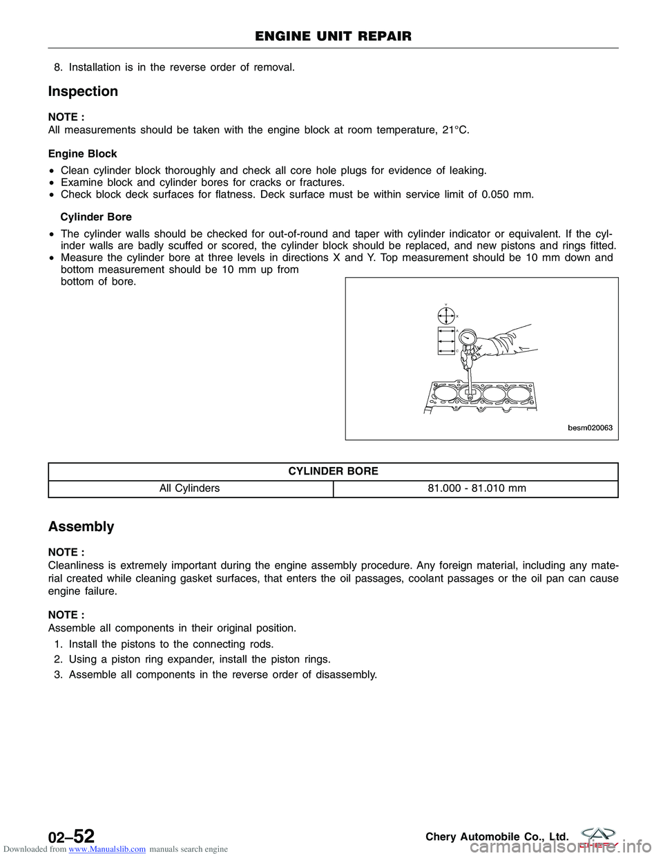
• Measure the cylinder bore at three levels in directions X and Y. Top measurement should be 10 mm down and
bottom measurement should be 10 mm up from
bottom of bore.
CYLINDER BORE
All Cylinders 81.000 - 81.010 mm
Assembly
NOTE :
Cleanliness is extremely important during the engine assembly procedure. Any foreign material, including any mate-
rial created while cleaning gasket surfaces, that enters the oil passages, coolant passages or the oil pan can cause
engine failure.
NOTE :
Assemble all components in their original position.
1. Install the pistons to the connecting rods.
2. Using a piston ring expander, install the piston rings.
3. Assemble all components in the reverse order of disassembly.
ENGINE UNIT REPAIR
BESM020063
02–52Chery Automobile Co., Ltd.
Page 119 of 1903
Downloaded from www.Manualslib.com manuals search engine Cylinder Compression Pressure Test
•The result of a cylinder compression pressure test can be utilized to diagnose several engine malfunctions.
• Ensure the battery is completely charged and the engine starter motor is in good operating condition. Otherwise
the indicated compression pressures may not be valid for diagnostic purposes.
� Check engine oil level and add oil if necessary.
� Disconnect the spark plug wires.
� Remove all spark plugs from engine (as spark plugs are being removed, check electrodes for abnormal
firing indicators fouled, hot, oily, etc.).
� Record cylinder number of each spark plug for future reference.
� Disconnect fuel injector electrical connectors.
� Be sure throttle blade is fully open during the compression check.
� Insert compression pressure adaptor or the equivalent into each spark plug hole in cylinder head.
� Crank engine until maximum pressure is reached on gauge. Record each cylinder pressure.
� Compression should not be less than 1000 kPa and not vary more than 25 percent from cylinder to cylinder.
� If one or more cylinders have abnormally low compression pressures, repeat the compression test.
� If the same cylinder or cylinders repeat an abnormally low reading on the second compression test, it could indicate the existence of a problem with the cylinder in question.
NOTE :
The recommended compression pressures are to be used only as a guide to diagnosing engine problems. An engine
should not be disassembled to determine the cause of low compression unless some malfunction is present.
Cylinder Head Gasket Test
• A cylinder head gasket leak can be located between adjacent cylinders, between a cylinder and the adjacent
water jacket or from an oil passage to the exterior of the engine.
• Possible indications of the cylinder head gasket leaking between adjacent cylinders are:
� Loss of engine power
� Engine misfiring
� Poor fuel economy
• Possible indications of the cylinder head gasket leaking between a cylinder and an adjacent water jacket are:
� Engine overheating
� Loss of coolant
� Excessive steam (white smoke) emitting from exhaust
� Coolant foaming
DIAGNOSIS & TESTING
02–90Chery Automobile Co., Ltd.
Page 127 of 1903
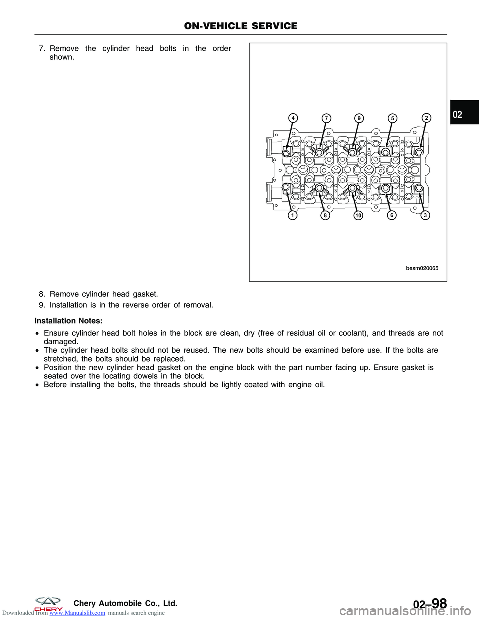
Downloaded from www.Manualslib.com manuals search engine 7. Remove the cylinder head bolts in the ordershown.
8. Remove cylinder head gasket.
9. Installation is in the reverse order of removal.
Installation Notes:
• Ensure cylinder head bolt holes in the block are clean, dry (free of residual oil or coolant), and threads are not
damaged.
• The cylinder head bolts should not be reused. The new bolts should be examined before use. If the bolts are
stretched, the bolts should be replaced.
• Position the new cylinder head gasket on the engine block with the part number facing up. Ensure gasket is
seated over the locating dowels in the block.
• Before installing the bolts, the threads should be lightly coated with engine oil.
ON-VEHICLE SERVICE
BESM020065
02
02–98Chery Automobile Co., Ltd.
Page 135 of 1903
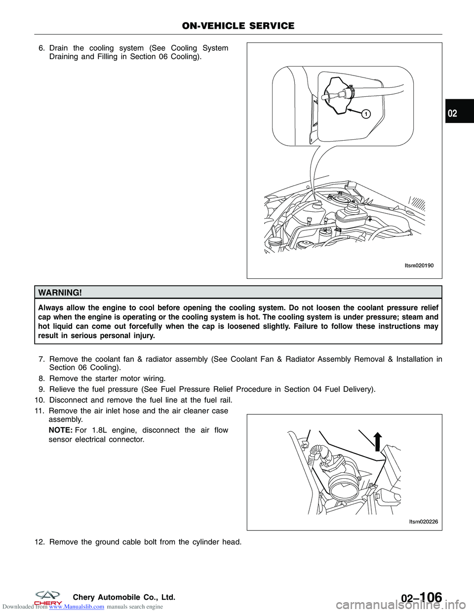
Downloaded from www.Manualslib.com manuals search engine 6. Drain the cooling system (See Cooling SystemDraining and Filling in Section 06 Cooling).
WARNING!
Always allow the engine to cool before opening the cooling system. Do not loosen the coolant pressure relief
cap when the engine is operating or the cooling system is hot. The cooling system is under pressure; steam and
hot liquid can come out forcefully when the cap is loosened slightly. Failure to follow these instructions may
result in serious personal injury.
7. Remove the coolant fan & radiator assembly (See Coolant Fan & Radiator Assembly Removal & Installation inSection 06 Cooling).
8. Remove the starter motor wiring.
9. Relieve the fuel pressure (See Fuel Pressure Relief Procedure in Section 04 Fuel Delivery).
10. Disconnect and remove the fuel line at the fuel rail.
11. Remove the air inlet hose and the air cleaner case assembly.
NOTE: For 1.8L engine, disconnect the air flow
sensor electrical connector.
12. Remove the ground cable bolt from the cylinder head.
ON-VEHICLE SERVICE
LTSM020190
LTSM020226
02
02–106Chery Automobile Co., Ltd.
Page 136 of 1903
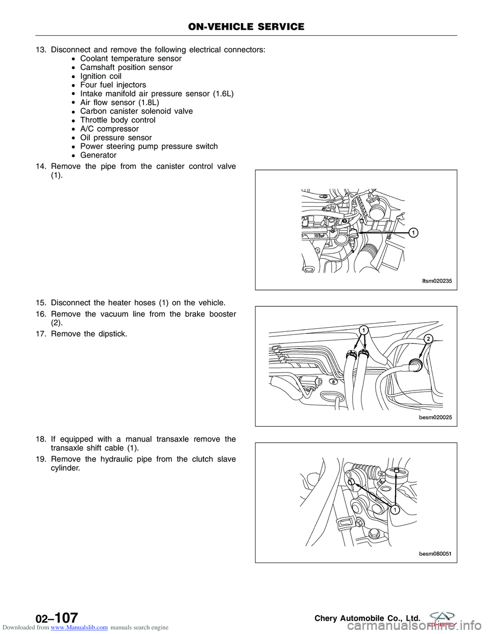
Downloaded from www.Manualslib.com manuals search engine 13.Disconnectandremovethefollowingelectricalconnectors:
€Coolanttemperaturesensor
€Camshaftpositionsensor
€Ignitioncoil
€Fourfuelinjectors
€Intakemanifoldairpressuresensor(1.6L)
€Airflowsensor(1.8L)
€Carboncanistersolenoidvalve
€Throttlebodycontrol
€A/Ccompressor
€Oilpressuresensor
€Powersteeringpumppressureswitch
€Generator
14.Removethepipefromthecanistercontrolvalve
(1).
15.Disconnecttheheaterhoses(1)onthevehicle.
16.Removethevacuumlinefromthebrakebooster
(2).
17.Removethedipstick.
18.Ifequippedwithamanualtransaxleremovethe
transaxleshiftcable(1).
19.Removethehydraulicpipefromtheclutchslave
cylinder.
ON-VEHICLESERVICE
LTSM020235
BESM020025
BESM080051
02–107CheryAutomobileCo.,Ltd.
Page 141 of 1903
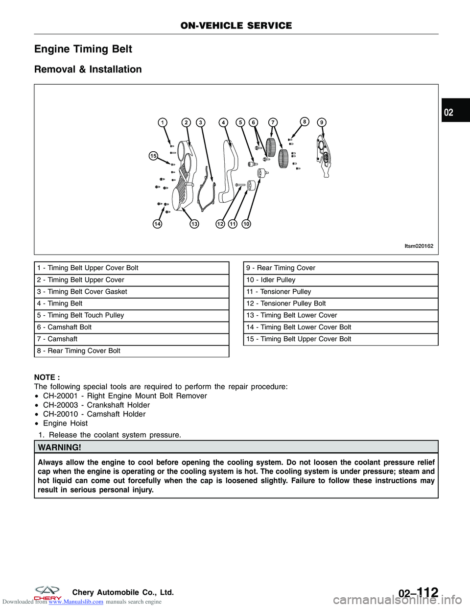
Downloaded from www.Manualslib.com manuals search engine Engine Timing Belt
Removal & Installation
NOTE :
The following special tools are required to perform the repair procedure:
•CH-20001 - Right Engine Mount Bolt Remover
• CH-20003 - Crankshaft Holder
• CH-20010 - Camshaft Holder
• Engine Hoist
1. Release the coolant system pressure.
WARNING!
Always allow the engine to cool before opening the cooling system. Do not loosen the coolant pressure relief
cap when the engine is operating or the cooling system is hot. The cooling system is under pressure; steam and
hot liquid can come out forcefully when the cap is loosened slightly. Failure to follow these instructions may
result in serious personal injury.
1 - Timing Belt Upper Cover Bolt
2 - Timing Belt Upper Cover
3 - Timing Belt Cover Gasket
4 - Timing Belt
5 - Timing Belt Touch Pulley
6 - Camshaft Bolt
7 - Camshaft
8 - Rear Timing Cover Bolt9 - Rear Timing Cover
10 - Idler Pulley
11 - Tensioner Pulley
12 - Tensioner Pulley Bolt
13 - Timing Belt Lower Cover
14 - Timing Belt Lower Cover Bolt
15 - Timing Belt Upper Cover Bolt
ON-VEHICLE SERVICE
LTSM020162
02
02–11 2Chery Automobile Co., Ltd.
Page 142 of 1903
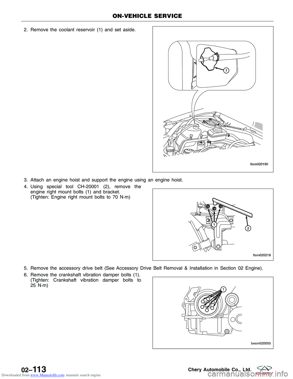
Downloaded from www.Manualslib.com manuals search engine 2. Remove the coolant reservoir (1) and set aside.
3. Attach an engine hoist and support the engine using an engine hoist.
4. Using special tool CH-20001 (2), remove theengine right mount bolts (1) and bracket.
(Tighten: Engine right mount bolts to 70 N·m)
5. Remove the accessory drive belt (See Accessory Drive Belt Removal & Installation in Section 02 Engine).
6. Remove the crankshaft vibration damper bolts (1). (Tighten: Crankshaft vibration damper bolts to
25 N·m)
ON-VEHICLE SERVICE
LTSM020190
LTSM020218
BESM020055
02–11 3Chery Automobile Co., Ltd.
Page 146 of 1903
Downloaded from www.Manualslib.com manuals search engine Installation Notes:
•Clean all surfaces of manifold and cylinder head.
• Install a new exhaust manifold gasket during installation.
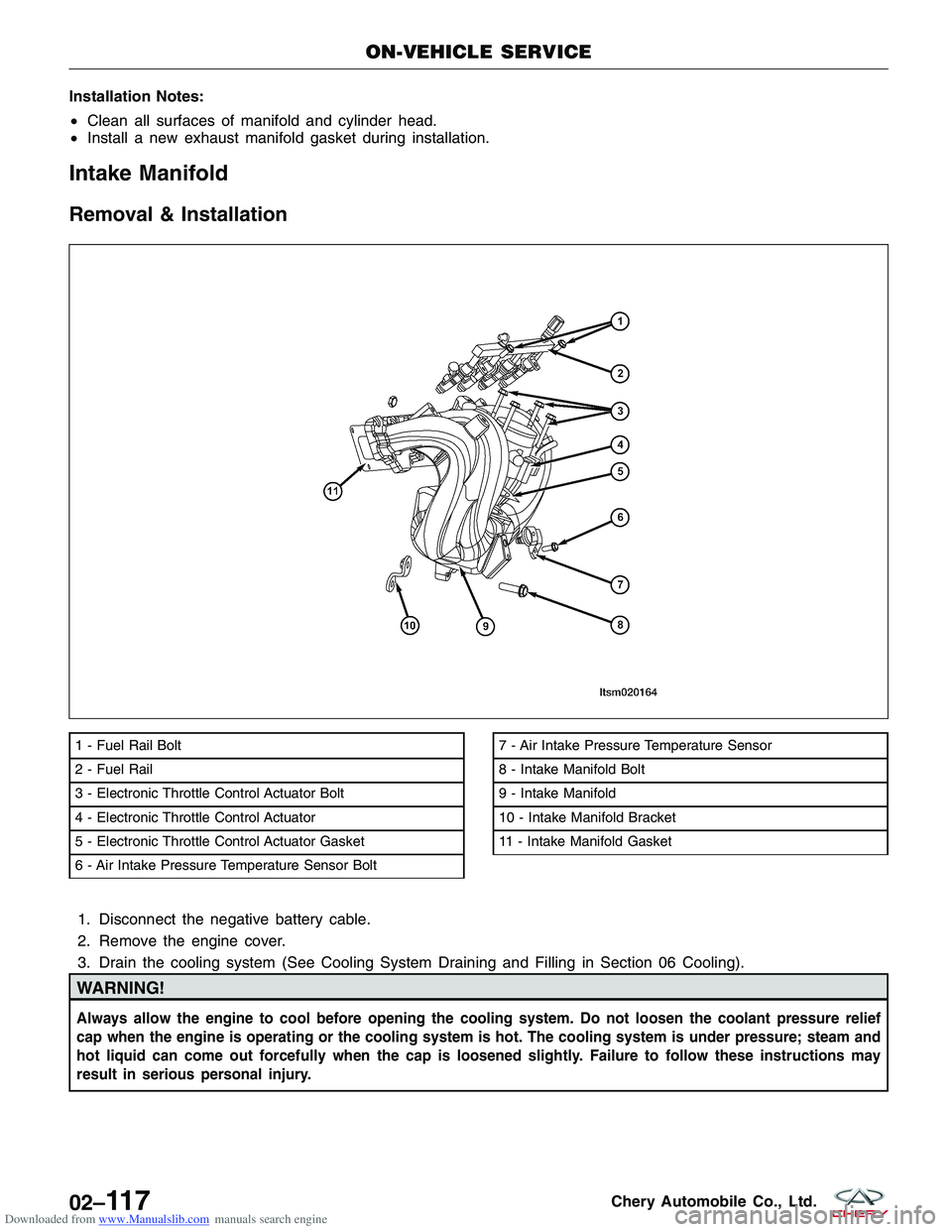
Intake Manifold
Removal & Installation
1. Disconnect the negative battery cable.
2. Remove the engine cover.
3. Drain the cooling system (See Cooling System Draining and Filling in Section 06 Cooling).
WARNING!
Always allow the engine to cool before opening the cooling system. Do not loosen the coolant pressure relief
cap when the engine is operating or the cooling system is hot. The cooling system is under pressure; steam and
hot liquid can come out forcefully when the cap is loosened slightly. Failure to follow these instructions may
result in serious personal injury.
1 - Fuel Rail Bolt
2 - Fuel Rail
3 - Electronic Throttle Control Actuator Bolt
4 - Electronic Throttle Control Actuator
5 - Electronic Throttle Control Actuator Gasket
6 - Air Intake Pressure Temperature Sensor Bolt7 - Air Intake Pressure Temperature Sensor
8 - Intake Manifold Bolt
9 - Intake Manifold
10 - Intake Manifold Bracket
11 - Intake Manifold Gasket
ON-VEHICLE SERVICE
LTSM020164
02–11 7Chery Automobile Co., Ltd.