headlamp CHERY TIGGO 2009 Service User Guide
[x] Cancel search | Manufacturer: CHERY, Model Year: 2009, Model line: TIGGO, Model: CHERY TIGGO 2009Pages: 1903, PDF Size: 33.38 MB
Page 1774 of 1903
Downloaded from www.Manualslib.com manuals search engine Headlamp Adjustment Procedure
NOTE :
Follow all local laws and regulations and verify the following items before adjustment:1. Check the following before starting the headlamp adjustment procedure: •All tires are filled to the proper tire pressure.
• The vehicle is unloaded (except for spare tire and tools, and include driver’s weight for sedan).
• The vehicle should be parked on a level surface.
• The headlights are clean.
• The headlights are working properly.
2. Park the vehicle on a level surface approximately 10 meters from the vertical wall or screen directly in front of it. NOTE: The vertical wall or screen must be a minimum of 2.4 meters wide.
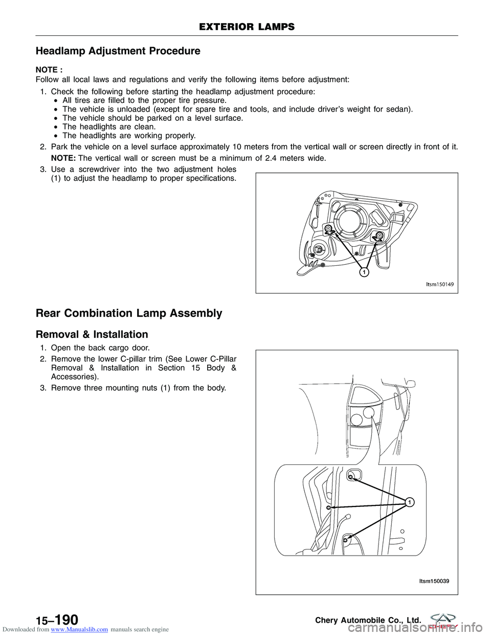
3. Use a screwdriver into the two adjustment holes (1) to adjust the headlamp to proper specifications.
Rear Combination Lamp Assembly
Removal & Installation
1. Open the back cargo door.
2. Remove the lower C-pillar trim (See Lower C-PillarRemoval & Installation in Section 15 Body &
Accessories).
3. Remove three mounting nuts (1) from the body.
EXTERIOR LAMPS
LTSM150149
LTSM150039
15–190Chery Automobile Co., Ltd.
Page 1775 of 1903
Downloaded from www.Manualslib.com manuals search engine 4. Disconnect the rear combination lamp.
5. Carefully remove the rear combination lamp assembly.
6. Installation is in the reverse order of removal.
Headlamp
Removal & Installation
1. Remove the front combination lamp assembly (See Front Combination Lamp Assembly Removal & Installation inSection 15 Body & Accessories).
2. Remove the headlamp bulb cover.
3. Disconnect the headlamp bulb electrical connector.
4. Remove the headlamp bulb clip.
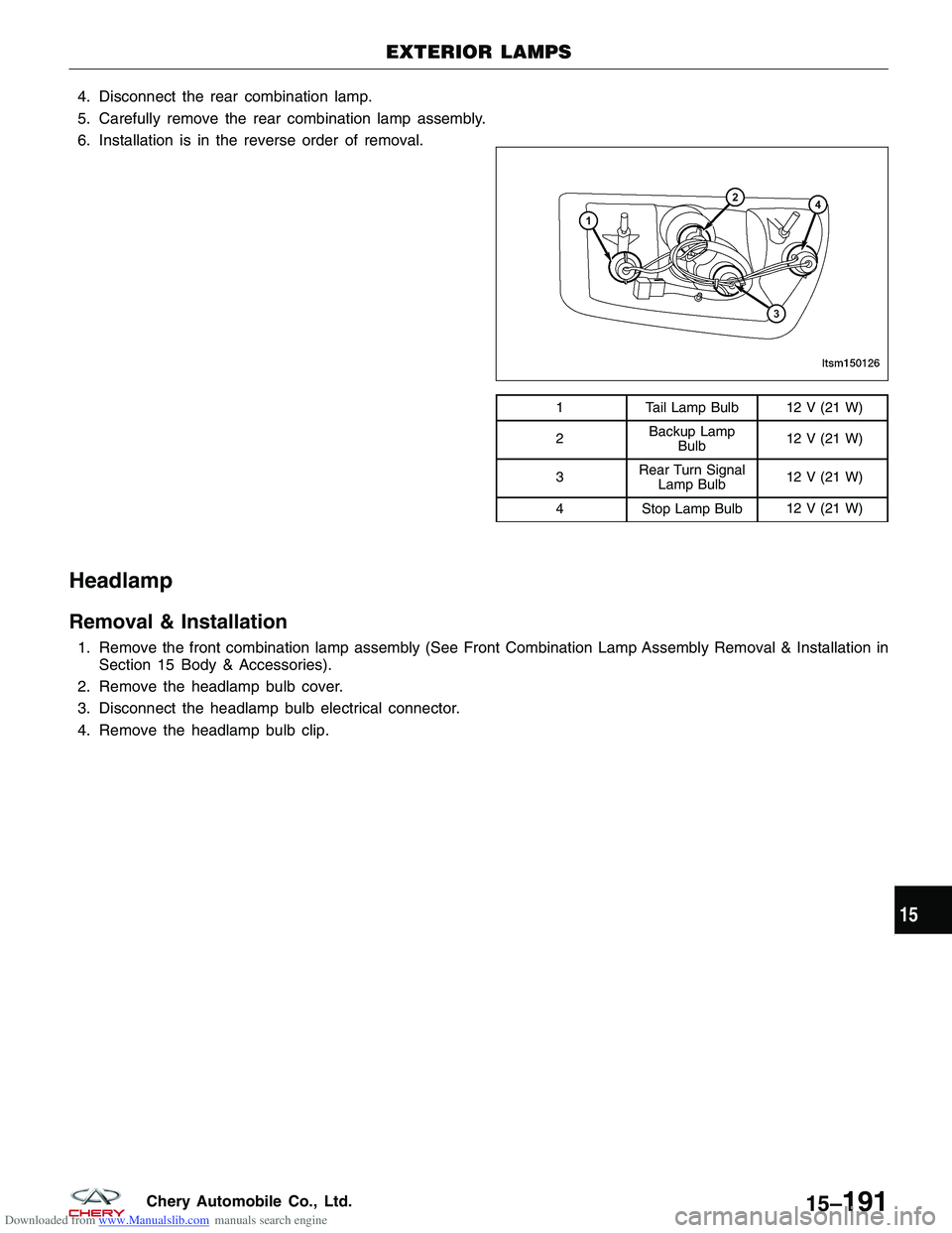
1 Tail Lamp Bulb 12 V (21 W)
2 Backup Lamp
Bulb 12 V (21 W)
3 Rear Turn Signal
Lamp Bulb 12 V (21 W)
4 Stop Lamp Bulb 12 V (21 W)
EXTERIOR LAMPS
LTSM150126
15
15–191Chery Automobile Co., Ltd.
Page 1776 of 1903
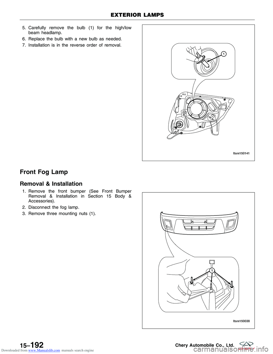
Downloaded from www.Manualslib.com manuals search engine 5. Carefully remove the bulb (1) for the high/lowbeam headlamp.
6. Replace the bulb with a new bulb as needed.
7. Installation is in the reverse order of removal.
Front Fog Lamp
Removal & Installation
1. Remove the front bumper (See Front Bumper Removal & Installation in Section 15 Body &
Accessories).
2. Disconnect the fog lamp.
3. Remove three mounting nuts (1).
EXTERIOR LAMPS
LTSM150141
LTSM150038
15–192Chery Automobile Co., Ltd.
Page 1792 of 1903
Downloaded from www.Manualslib.com manuals search engine Horn
Removal & Installation
1. Remove the right headlamp assembly.
2. Disconnect the horn electrical connector.
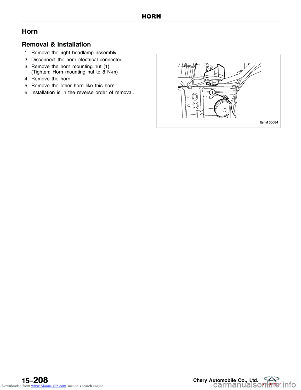
3. Remove the horn mounting nut (1).(Tighten: Horn mounting nut to 8 N·m)
4. Remove the horn.
5. Remove the other horn like this horn.
6. Installation is in the reverse order of removal.
HORN
LTSM150084
15–208Chery Automobile Co., Ltd.
Page 1885 of 1903
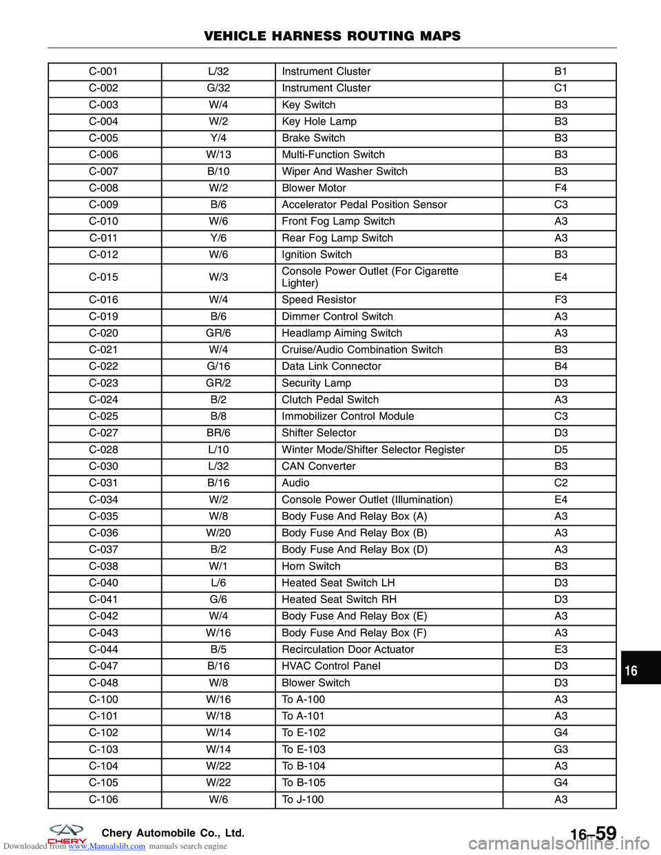
Downloaded from www.Manualslib.com manuals search engine C-001L/32 Instrument Cluster B1
C-002 G/32 Instrument Cluster C1
C-003 W/4 Key Switch B3
C-004 W/2 Key Hole Lamp B3
C-005 Y/4Brake Switch B3
C-006 W/13 Multi-Function Switch B3
C-007 B/10 Wiper And Washer Switch B3
C-008 W/2 Blower Motor F4
C-009 B/6Accelerator Pedal Position Sensor C3
C-010 W/6 Front Fog Lamp Switch A3
C-011 Y/6Rear Fog Lamp Switch A3
C-012 W/6 Ignition Switch B3
C-015 W/3Console Power Outlet (For Cigarette
Lighter) E4
C-016 W/4 Speed Resistor F3
C-019 B/6Dimmer Control Switch A3
C-020 GR/6 Headlamp Aiming Switch A3
C-021 W/4 Cruise/Audio Combination Switch B3
C-022 G/16 Data Link Connector B4
C-023 GR/2 Security Lamp D3
C-024 B/2Clutch Pedal Switch A3
C-025 B/8Immobilizer Control Module C3
C-027 BR/6 Shifter Selector D3
C-028 L/10 Winter Mode/Shifter Selector Register D5
C-030 L/32 CAN Converter B3
C-031 B/16 Audio C2
C-034 W/2 Console Power Outlet (Illumination) E4
C-035 W/8 Body Fuse And Relay Box (A) A3
C-036 W/20 Body Fuse And Relay Box (B) A3
C-037 B/2Body Fuse And Relay Box (D) A3
C-038 W/1 Horn Switch B3
C-040 L/6Heated Seat Switch LH D3
C-041 G/6Heated Seat Switch RH D3
C-042 W/4 Body Fuse And Relay Box (E) A3
C-043 W/16 Body Fuse And Relay Box (F) A3
C-044 B/5Recirculation Door Actuator E3
C-047 B/16 HVAC Control Panel D3
C-048 W/8 Blower Switch D3
C-100 W/16 To A-100 A3
C-101 W/18 To A-101 A3
C-102 W/14 To E-102 G4
C-103 W/14 To E-103 G3
C-104 W/22 To B-104 A3
C-105 W/22 To B-105 G4
C-106 W/6 To J-100 A3
VEHICLE HARNESS ROUTING MAPS
16
16–59Chery Automobile Co., Ltd.
Page 1899 of 1903
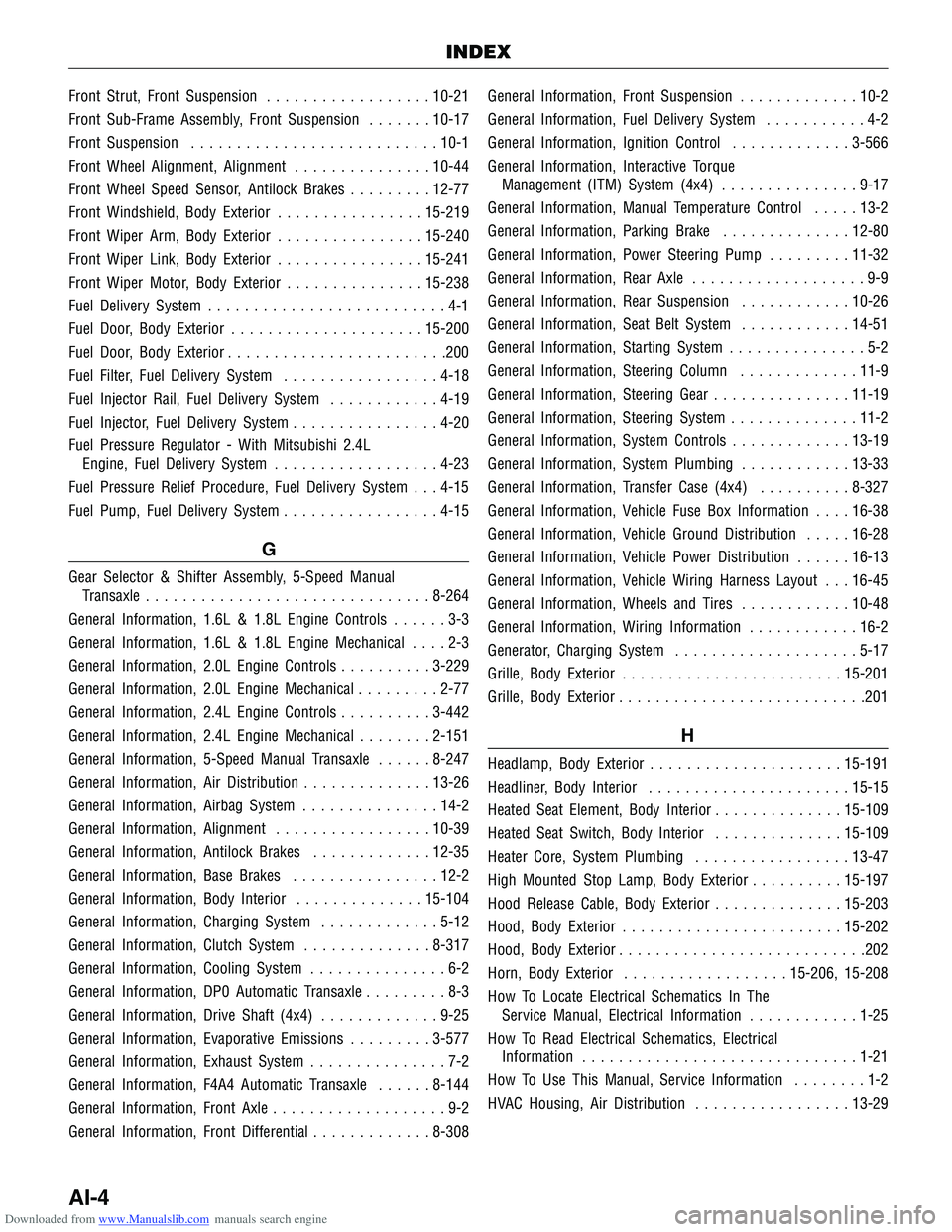
Downloaded from www.Manualslib.com manuals search engine Front Strut, Front Suspension..................10-21
Front Sub-Frame Assembly, Front Suspension .......10-17
Front Suspension ........................... 10-1
Front Wheel Alignment, Alignment ...............10-44
Front Wheel Speed Sensor, Antilock Brakes .........12-77
Front Windshield, Body Exterior ................15-219
Front Wiper Arm, Body Exterior ................15-240
Front Wiper Link, Body Exterior ................15-241
Front Wiper Motor, Body Exterior ...............15-238
Fuel Delivery System ..........................4-1
Fuel Door, Body Exterior ..................... 15-200
Fuel Door, Body Exterior ........................200
Fuel Filter, Fuel Delivery System .................4-18
Fuel Injector Rail, Fuel Delivery System ............4-19
Fuel Injector, Fuel Delivery System ................4-20
Fuel Pressure Regulator - With Mitsubishi 2.4L Engine, Fuel Delivery System ..................4-23
Fuel Pressure Relief Procedure, Fuel Delivery System . . . 4-15
Fuel Pump, Fuel Delivery System .................4-15
G
Gear Selector & Shifter Assembly, 5-Speed Manual
Transaxle ............................... 8-264
General Information, 1.6L & 1.8L Engine Controls ......3-3
General Information, 1.6L & 1.8L Engine Mechanical ....2-3
General Information, 2.0L Engine Controls ..........3-229
General Information, 2.0L Engine Mechanical .........2-77
General Information, 2.4L Engine Controls ..........3-442
General Information, 2.4L Engine Mechanical ........2-151
General Information, 5-Speed Manual Transaxle ......8-247
General Information, Air Distribution ..............13-26
General Information, Airbag System ...............14-2
General Information, Alignment .................10-39
General Information, Antilock Brakes .............12-35
General Information, Base Brakes ................12-2
General Information, Body Interior ..............15-104
General Information, Charging System .............5-12
General Information, Clutch System ..............8-317
General Information, Cooling System ...............6-2
General Information, DP0 Automatic Transaxle .........8-3
General Information, Drive Shaft (4x4) .............9-25
General Information, Evaporative Emissions .........3-577
General Information, Exhaust System ...............7-2
General Information, F4A4 Automatic Transaxle ......8-144
General Information, Front Axle ...................9-2
General Information, Front Differential .............8-308General Information, Front Suspension
.............10-2
General Information, Fuel Delivery System ...........4-2
General Information, Ignition Control .............3-566
General Information, Interactive Torque Management (ITM) System (4x4) ...............9-17
General Information, Manual Temperature Control .....13-2
General Information, Parking Brake ..............12-80
General Information, Power Steering Pump .........11-32
General Information, Rear Axle ...................9-9
General Information, Rear Suspension ............10-26
General Information, Seat Belt System ............14-51
General Information, Starting System ...............5-2
General Information, Steering Column .............11-9
General Information, Steering Gear ...............11-19
General Information, Steering System ..............11-2
General Information, System Controls .............13-19
General Information, System Plumbing ............13-33
General Information, T
ransfer Case (4x4)..........8-327
General Information, Vehicle Fuse Box Information ....16-38
General Information, Vehicle Ground Distribution .....16-28
General Information, Vehicle Power Distribution ......16-13
General Information, Vehicle Wiring Harness Layout . . . 16-45
General Information, Wheels and Tires ............10-48
General Information, Wiring Information ............16-2
Generator, Charging System ....................5-17
Grille, Body Exterior ........................ 15-201
Grille, Body Exterior ...........................201
H
Headlamp, Body Exterior ..................... 15-191
Headliner, Body Interior ...................... 15-15
Heated Seat Element, Body Interior ..............15-109
Heated Seat Switch, Body Interior ..............15-109
Heater Core, System Plumbing .................13-47
High Mounted Stop Lamp, Body Exterior ..........15-197
Hood Release Cable, Body Exterior ..............15-203
Hood, Body Exterior ........................ 15-202
Hood, Body Exterior ...........................202
Horn, Body Exterior .................. 15-206, 15-208
How To Locate Electrical Schematics In The Service Manual, Electrical Information ............1-25
How To Read Electrical Schematics, Electrical Information .............................. 1-21
How To Use This Manual, Service Information ........1-2
HVAC Housing, Air Distribution .................13-29
INDEX
AI-4