clock CHERY TIGGO 2009 Service Repair Manual
[x] Cancel search | Manufacturer: CHERY, Model Year: 2009, Model line: TIGGO, Model: CHERY TIGGO 2009Pages: 1903, PDF Size: 33.38 MB
Page 5 of 1903
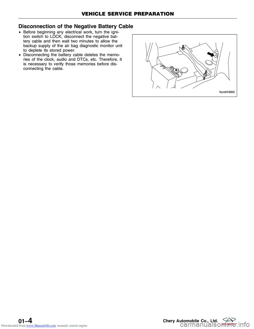
Downloaded from www.Manualslib.com manuals search engine Disconnection of the Negative Battery Cable
•Before beginning any electrical work, turn the igni-
tion switch to LOCK, disconnect the negative bat-
tery cable and then wait two minutes to allow the
backup supply of the air bag diagnostic monitor unit
to deplete its stored power.
• Disconnecting the battery cable deletes the memo-
ries of the clock, audio and DTCs, etc. Therefore, it
is necessary to verify those memories before dis-
connecting the cable.
VEHICLE SERVICE PREPARATION
LTSM010002
01–4Chery Automobile Co., Ltd.
Page 46 of 1903
Downloaded from www.Manualslib.com manuals search engine ON-VEHICLE SERVICE
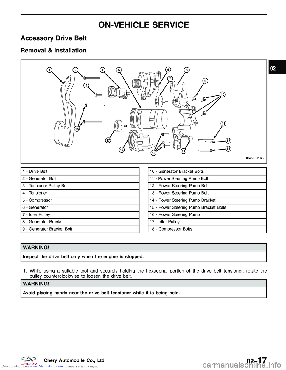
Accessory Drive Belt
Removal & Installation
WARNING!
Inspect the drive belt only when the engine is stopped.
1. While using a suitable tool and securely holding the hexagonal portion of the drive belt tensioner, rotate thepulley counterclockwise to loosen the drive belt.
WARNING!
Avoid placing hands near the drive belt tensioner while it is being held.
1 - Drive Belt
2 - Generator Bolt
3 - Tensioner Pulley Bolt
4 - Tensioner
5 - Compressor
6 - Generator
7 - Idler Pulley
8 - Generator Bracket
9 - Generator Bracket Bolt10 - Generator Bracket Bolts
11 - Power Steering Pump Bolt
12 - Power Steering Pump Bolt
13 - Power Steering Pump Bolt
14 - Power Steering Pump Bracket
15 - Power Steering Pump Bracket Bolts
16 - Power Steering Pump
17 - Idler Pulley
18 - Compressor Bolts
LTSM020163
02
02–17Chery Automobile Co., Ltd.
Page 74 of 1903
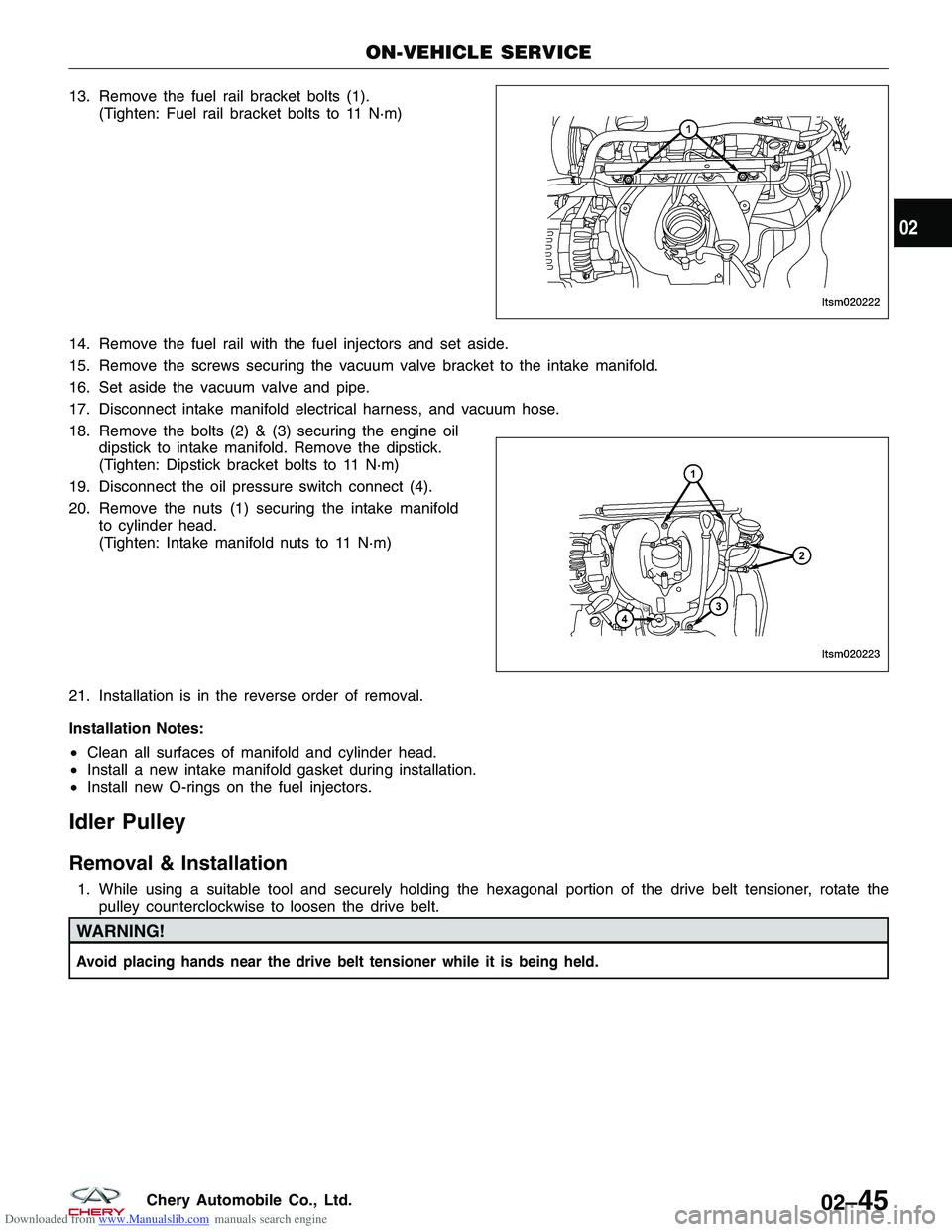
Downloaded from www.Manualslib.com manuals search engine 13. Remove the fuel rail bracket bolts (1).(Tighten: Fuel rail bracket bolts to 11 N·m)
14. Remove the fuel rail with the fuel injectors and set aside.
15. Remove the screws securing the vacuum valve bracket to the intake manifold.
16. Set aside the vacuum valve and pipe.
17. Disconnect intake manifold electrical harness, and vacuum hose.
18. Remove the bolts (2) & (3) securing the engine oil dipstick to intake manifold. Remove the dipstick.
(Tighten: Dipstick bracket bolts to 11 N·m)
19. Disconnect the oil pressure switch connect (4).
20. Remove the nuts (1) securing the intake manifold to cylinder head.
(Tighten: Intake manifold nuts to 11 N·m)
21. Installation is in the reverse order of removal.
Installation Notes:
• Clean all surfaces of manifold and cylinder head.
• Install a new intake manifold gasket during installation.
• Install new O-rings on the fuel injectors.
Idler Pulley
Removal & Installation
1. While using a suitable tool and securely holding the hexagonal portion of the drive belt tensioner, rotate the
pulley counterclockwise to loosen the drive belt.
WARNING!
Avoid placing hands near the drive belt tensioner while it is being held.
ON-VEHICLE SERVICE
LTSM020222
LTSM020223
02
02–45Chery Automobile Co., Ltd.
Page 120 of 1903
Downloaded from www.Manualslib.com manuals search engine ON-VEHICLE SERVICE
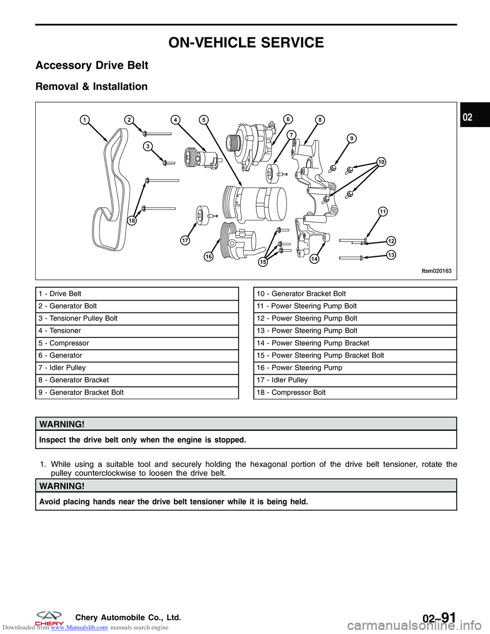
Accessory Drive Belt
Removal & Installation
WARNING!
Inspect the drive belt only when the engine is stopped.
1. While using a suitable tool and securely holding the hexagonal portion of the drive belt tensioner, rotate thepulley counterclockwise to loosen the drive belt.
WARNING!
Avoid placing hands near the drive belt tensioner while it is being held.
1 - Drive Belt
2 - Generator Bolt
3 - Tensioner Pulley Bolt
4 - Tensioner
5 - Compressor
6 - Generator
7 - Idler Pulley
8 - Generator Bracket
9 - Generator Bracket Bolt10 - Generator Bracket Bolt
11 - Power Steering Pump Bolt
12 - Power Steering Pump Bolt
13 - Power Steering Pump Bolt
14 - Power Steering Pump Bracket
15 - Power Steering Pump Bracket Bolt
16 - Power Steering Pump
17 - Idler Pulley
18 - Compressor Bolt
LTSM020163
02
02–91Chery Automobile Co., Ltd.
Page 148 of 1903
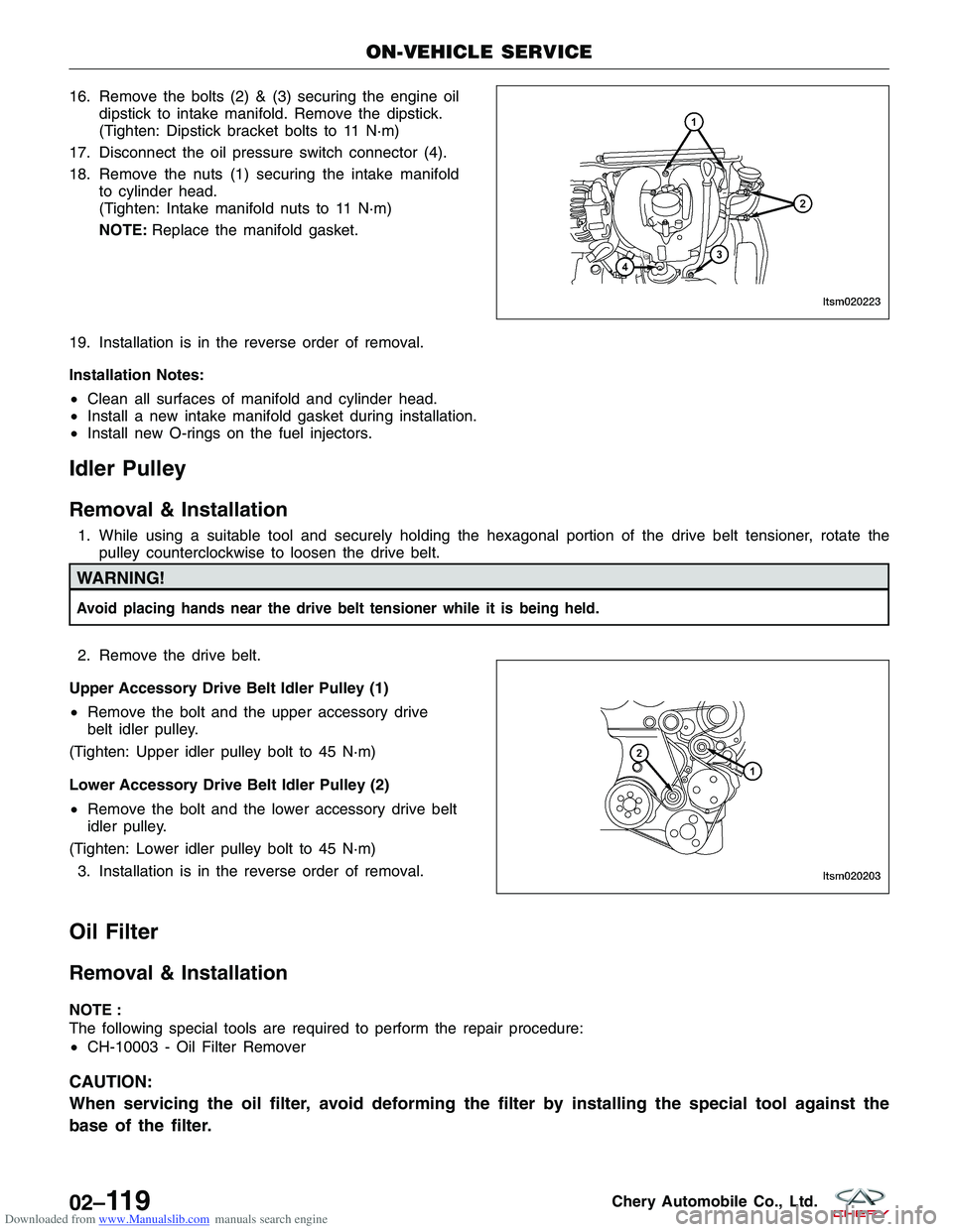
Downloaded from www.Manualslib.com manuals search engine 16. Remove the bolts (2) & (3) securing the engine oildipstick to intake manifold. Remove the dipstick.
(Tighten: Dipstick bracket bolts to 11 N·m)
17. Disconnect the oil pressure switch connector (4).
18. Remove the nuts (1) securing the intake manifold to cylinder head.
(Tighten: Intake manifold nuts to 11 N·m)
NOTE: Replace the manifold gasket.
19. Installation is in the reverse order of removal.
Installation Notes:
• Clean all surfaces of manifold and cylinder head.
• Install a new intake manifold gasket during installation.
• Install new O-rings on the fuel injectors.
Idler Pulley
Removal & Installation
1. While using a suitable tool and securely holding the hexagonal portion of the drive belt tensioner, rotate the
pulley counterclockwise to loosen the drive belt.
WARNING!
Avoid placing hands near the drive belt tensioner while it is being held.
2. Remove the drive belt.
Upper Accessory Drive Belt Idler Pulley (1)
• Remove the bolt and the upper accessory drive
belt idler pulley.
(Tighten: Upper idler pulley bolt to 45 N·m)
Lower Accessory Drive Belt Idler Pulley (2)
• Remove the bolt and the lower accessory drive belt
idler pulley.
(Tighten: Lower idler pulley bolt to 45 N·m) 3. Installation is in the reverse order of removal.
Oil Filter
Removal & Installation
NOTE :
The following special tools are required to perform the repair procedure:
• CH-10003 - Oil Filter Remover
CAUTION:
When servicing the oil filter, avoid deforming the filter by installing the special tool against the
base of the filter.
ON-VEHICLE SERVICE
LTSM020223
LTSM020203
02–11 9Chery Automobile Co., Ltd.
Page 501 of 1903
Downloaded from www.Manualslib.com manuals search engine ON-VEHICLE SERVICE
Engine Coolant Temperature (ECT) Sensor
Description
The Engine Coolant Temperature (ECT) sensor threads into the coolant outlet connector. The ECT is a negative
thermal coefficient sensor.
Operation
The ECT provides an input to the Engine Control Module (ECM). As temperature increases, resistance of the sensor
decreases. As coolant temperature varies, the ECT sensor resistance changes resulting in a different voltage value
at the ECT sensor signal circuit. The ECM uses the input to control air-fuel mixture, timing, A/C compressor and
radiator fan on/off times.
Removal & Installation
1. Disconnect the negative battery cable.
2. Drain the cooling system (See Cooling System Draining Procedure in Section 06 Cooling System).
WARNING!
Never remove the pressure relief cap under any conditions while the engine is operating or hot. Failure to follow
these instructions could result in personal injury or damage to the cooling system or engine. To avoid having
scalding hot coolant or steam blow out of the cooling system, use extreme care when removing the pressure
relief cap. Wait until the engine has cooled, then wrap a thick cloth around the pressure relief cap and turn it
slowly one turn (counterclockwise). Step back while the pressure is released from the cooling system. When you
are certain all the pressure has been released, (with a cloth) turn and remove the pressure relief cap. Failure to
follow these instructions may result in serious personal injury.
3. Disconnect the coolant temperature sensor electri-cal connector.
CAUTION:
Remove the coolant temperature sensor when
the engine is cold.
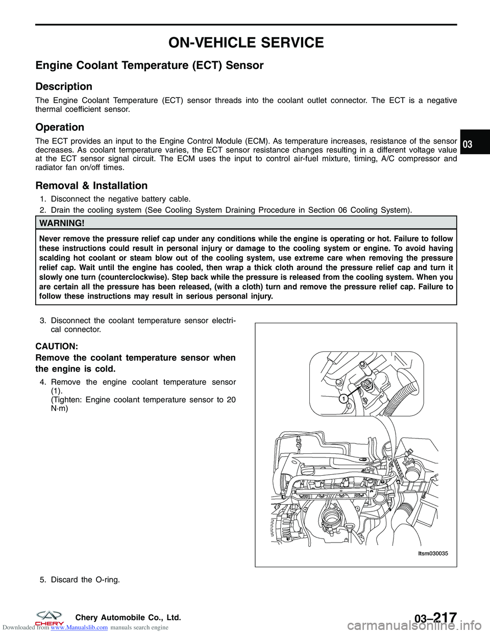
4. Remove the engine coolant temperature sensor(1).
(Tighten: Engine coolant temperature sensor to 20
N·m)
5. Discard the O-ring.
LTSM030035
03
03–217Chery Automobile Co., Ltd.
Page 711 of 1903
Downloaded from www.Manualslib.com manuals search engine ON-VEHICLE SERVICE
Engine Coolant Temperature (ECT) Sensor
Description
The Engine Coolant Temperature (ECT) sensor threads into the coolant outlet connector. The ECT is a negative
thermal coefficient sensor.
Operation
The ECT provides an input to the Engine Control Module (ECM). As temperature increases, resistance of the sensor
decreases. As coolant temperature varies, the ECT sensor resistance changes resulting in a different voltage value
at the ECT sensor signal circuit. The ECM uses the input to control air-fuel mixture, timing, A/C compressor and
radiator fan on/off times.
Removal & Installation
1. Disconnect the negative battery cable.
2. Drain the cooling system (See Cooling System Draining Procedure in Section 06 Cooling System).
WARNING!
Never remove the pressure relief cap under any conditions while the engine is operating or hot. Failure to follow
these instructions could result in personal injury or damage to the cooling system or engine. To avoid having
scalding hot coolant or steam blow out of the cooling system, use extreme care when removing the pressure
relief cap. Wait until the engine has cooled, then wrap a thick cloth around the pressure relief cap and turn it
slowly one turn (counterclockwise). Step back while the pressure is released from the cooling system. When you
are certain all the pressure has been released, (with a cloth) turn and remove the pressure relief cap. Failure to
follow these instructions may result in series personal injury.
3. Disconnect the coolant temperature sensor electri-cal connector.
CAUTION:
Remove the coolant temperature sensor when
the engine is cold.
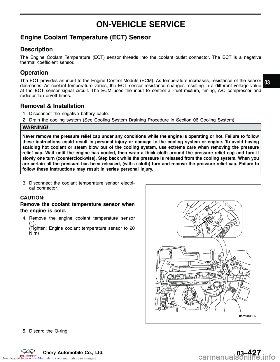
4. Remove the engine coolant temperature sensor(1).
(Tighten: Engine coolant temperature sensor to 20
N·m)
5. Discard the O-ring.
LTSM030035
03
03–427Chery Automobile Co., Ltd.
Page 815 of 1903
Downloaded from www.Manualslib.com manuals search engine ON-VEHICLE SERVICE
Engine Coolant Temperature (ECT) Sensor
Description
The Engine Coolant Temperature (ECT) Sensor is beside the thermostat. The ECT Sensor is a negative thermal
coefficient sensor.
Operation
The ECT sensor provides an input signal to the ECM. As temperature increases, resistance of the sensor decreases.
As coolant temperature varies, the ECT sensor resistance changes resulting in a different voltage value at the ECT
sensor signal circuit. The ECM uses the input to control air-fuel mixture, timing, and radiator fan on/off times.
Removal & Installation
1. Disconnect and isolate the negative battery cable.
2. Release the coolant system pressure.
WARNING!
Never remove the radiator pressure relief cap under any conditions while the engine is operating or hot. Failure
to follow these instructions could result in personal injury or damage to the cooling system or engine. To avoid
having scalding hot coolant or steam blow out of the cooling system, use extreme care when removing the pres-
sure relief cap. Wait until the engine has cooled, then wrap a thick cloth around the pressure relief cap and turn
it slowly one turn (counterclockwise). Step back while the pressure is released from the cooling system. When
you are certain all the pressure has been released, (with a cloth) turn and remove the pressure relief cap. Failure
to follow these instructions may result in serious personal injury.
3. Disconnect the coolant temperature sensor electrical connector.
CAUTION:
Remove the coolant temperature sensor when the engine is cold.
03
03–531Chery Automobile Co., Ltd.
Page 928 of 1903
Downloaded from www.Manualslib.com manuals search engine ON-VEHICLE SERVICE
Cooling System Draining and Filling
Cooling System Draining Procedure
WARNING!
Never remove the pressure relief cap, under any conditions, while the engine is operating or hot. Failure to fol-
low these instructions could result in personal injury or damage to the cooling system or engine. To avoid hav-
ing scalding hot coolant or steam blow out of the cooling system, use extreme care when removing the pressure
relief cap. Wait until the engine has cooled, then wrap a thick cloth around the pressure relief cap and turn it
slowly one turn (counterclockwise). Step back while the pressure is released from the cooling system. When you
are certain all the pressure has been released, using a cloth turn and remove the pressure relief cap. Failure to
follow these instructions may result in serious personal injury.
Perform the following procedure when draining the cooling system.1. Do not remove the pressure cap first.
2. With the engine cold, remove the pressure cap.
3. Raise and support the vehicle and locate the radiator drain plug.
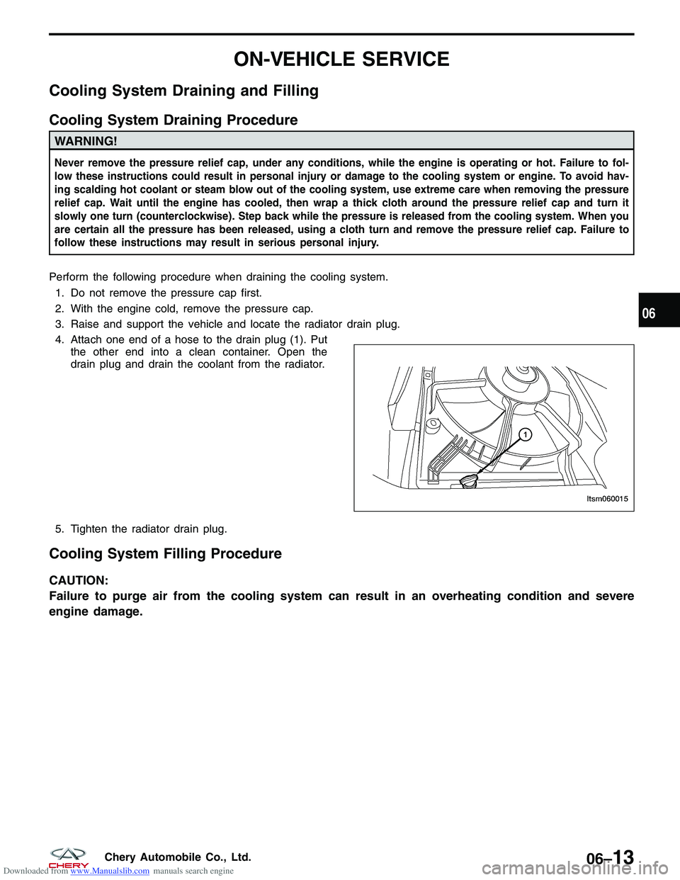
4. Attach one end of a hose to the drain plug (1). Put the other end into a clean container. Open the
drain plug and drain the coolant from the radiator.
5. Tighten the radiator drain plug.
Cooling System Filling Procedure
CAUTION:
Failure to purge air from the cooling system can result in an overheating condition and severe
engine damage.
LTSM060015
06
06–13Chery Automobile Co., Ltd.
Page 1636 of 1903
Downloaded from www.Manualslib.com manuals search engine INSTRUMENT CLUSTER
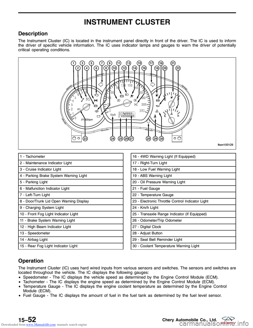
Description
The Instrument Cluster (IC) is located in the instrument panel directly in front of the driver. The IC is used to inform
the driver of specific vehicle information. The IC uses indicator lamps and gauges to warn the driver of potentially
critical operating conditions.
Operation
The Instrument Cluster (IC) uses hard wired inputs from various sensors and switches. The sensors and switches are
located throughout the vehicle. The IC displays the following gauges:
•Speedometer - The IC displays the vehicle speed as determined by the Engine Control Module (ECM).
• Tachometer - The IC displays the engine speed as determined by the Engine Control Module (ECM).
• Temperature Gauge - The IC displays the engine coolant temperature as determined by the Engine Control
Module (ECM).
• Fuel Gauge - The IC displays the amount of fuel in the fuel tank as determined by the fuel level sensor.
1 - Tachometer
2 - Maintenance Indicator Light
3 - Cruise Indicator Light
4 - Parking Brake System Warning Light
5 - Parking Light
6 - Malfunction Indicator Light
7 - Left-Turn Light
8 - Door/Trunk Lid Open Warning Display
9 - Charging System Light
10 - Front Fog Light Indicator Light
11 - Brake System Warning Light
12 - High Beam Indicator Light
13 - Speedometer
14 - Airbag Light
15 - Rear Fog Light Indicator Light16 - 4WD Warning Light (If Equipped)
17 - Right-Turn Light
18 - Low Fuel Warning Light
19 - ABS Warning Light
20 - Oil Pressure Warning Light
21 - Fuel Gauge
22 - Temperature Gauge
23 - Electronic Throttle Control Indicator Light
24 - Km/h Light
25 - Transaxle Range Indicator (If Equipped)
26 - Odometer/Trip Odometer
27 - Digital Clock
28 - Adjust Button
29 - Seat Belt Reminder Light
30 - Coolant Temperature Warning Light
LTSM150129
15–52Chery Automobile Co., Ltd.