overheating CHERY TIGGO 2009 Service Repair Manual
[x] Cancel search | Manufacturer: CHERY, Model Year: 2009, Model line: TIGGO, Model: CHERY TIGGO 2009Pages: 1903, PDF Size: 33.38 MB
Page 45 of 1903
Downloaded from www.Manualslib.com manuals search engine Cylinder Compression Pressure Test
•The result of a cylinder compression pressure test can be utilized to diagnose several engine malfunctions.
• Ensure the battery is completely charged and the engine starter motor is in good operating condition. Otherwise
the indicated compression pressures may not be valid for diagnostic purposes.
� Check engine oil level and add oil if necessary.
� Disconnect the spark plug wires.
� Remove all spark plugs from engine (as spark plugs are being removed, check electrodes for abnormal
firing indicators fouled, hot, oily, etc.).
� Record cylinder number of each spark plug for future reference.
� Disconnect fuel injector electrical connectors.
� Be sure throttle blade is fully open during the compression check.
� Insert compression pressure adaptor or the equivalent into each spark plug hole in cylinder head.
� Crank engine until maximum pressure is reached on gauge. Record each cylinder pressure.
� Compression should not be less than 1000 kPa and not vary more than 25 percent from cylinder to cylinder.
� If one or more cylinders have abnormally low compression pressures, repeat the compression test.
� If the same cylinder or cylinders repeat an abnormally low reading on the second compression test, it could indicate the existence of a problem with the cylinder in question.
NOTE :
The recommended compression pressures are to be used only as a guide to diagnosing engine problems. An engine
should not be disassembled to determine the cause of low compression unless some malfunction is present.
Cylinder Head Gasket Test
• A cylinder head gasket leak can be located between adjacent cylinders, between a cylinder and the adjacent
water jacket or from an oil passage to the exterior of the engine.
• Possible indications of the cylinder head gasket leaking between adjacent cylinders are:
� Loss of engine power
� Engine misfiring
� Poor fuel economy
• Possible indications of the cylinder head gasket leaking between a cylinder and an adjacent water jacket are:
� Engine overheating
� Loss of coolant
� Excessive steam (white smoke) emitting from exhaust
� Coolant foaming
DIAGNOSIS & TESTING
02–16Chery Automobile Co., Ltd.
Page 119 of 1903
Downloaded from www.Manualslib.com manuals search engine Cylinder Compression Pressure Test
•The result of a cylinder compression pressure test can be utilized to diagnose several engine malfunctions.
• Ensure the battery is completely charged and the engine starter motor is in good operating condition. Otherwise
the indicated compression pressures may not be valid for diagnostic purposes.
� Check engine oil level and add oil if necessary.
� Disconnect the spark plug wires.
� Remove all spark plugs from engine (as spark plugs are being removed, check electrodes for abnormal
firing indicators fouled, hot, oily, etc.).
� Record cylinder number of each spark plug for future reference.
� Disconnect fuel injector electrical connectors.
� Be sure throttle blade is fully open during the compression check.
� Insert compression pressure adaptor or the equivalent into each spark plug hole in cylinder head.
� Crank engine until maximum pressure is reached on gauge. Record each cylinder pressure.
� Compression should not be less than 1000 kPa and not vary more than 25 percent from cylinder to cylinder.
� If one or more cylinders have abnormally low compression pressures, repeat the compression test.
� If the same cylinder or cylinders repeat an abnormally low reading on the second compression test, it could indicate the existence of a problem with the cylinder in question.
NOTE :
The recommended compression pressures are to be used only as a guide to diagnosing engine problems. An engine
should not be disassembled to determine the cause of low compression unless some malfunction is present.
Cylinder Head Gasket Test
• A cylinder head gasket leak can be located between adjacent cylinders, between a cylinder and the adjacent
water jacket or from an oil passage to the exterior of the engine.
• Possible indications of the cylinder head gasket leaking between adjacent cylinders are:
� Loss of engine power
� Engine misfiring
� Poor fuel economy
• Possible indications of the cylinder head gasket leaking between a cylinder and an adjacent water jacket are:
� Engine overheating
� Loss of coolant
� Excessive steam (white smoke) emitting from exhaust
� Coolant foaming
DIAGNOSIS & TESTING
02–90Chery Automobile Co., Ltd.
Page 195 of 1903
Downloaded from www.Manualslib.com manuals search engine Cylinder Head Gasket Test
•A cylinder head gasket leak can be located between adjacent cylinders, between a cylinder and the adjacent
water jacket or from an oil passage to the exterior of the engine.
• Possible indications of the cylinder head gasket leaking between adjacent cylinders are:
� Loss of engine power
� Engine misfiring
� Poor fuel economy
• Possible indications of the cylinder head gasket leaking between a cylinder and an adjacent water jacket are:
� Engine overheating
� Loss of coolant
� Excessive steam (white smoke) emitting from exhaust
� Coolant foaming
Engine Oil Pressure Test
1. Check the engine oil level.
2. Disconnect the oil pressure switch electrical connector.
3. Remove the oil pressure switch.
4. Install the mechanical oil pressure gauge.
5. Start the engine and warm to normal operating temperature.
6. After the engine has been warmed up, check that the oil pressure is within the specifications. � Standard Oil Pressure: At 750 ± 50 RPM: 0.8 MPa
7. Stop the engine.
8. Remove the oil pressure gauge.
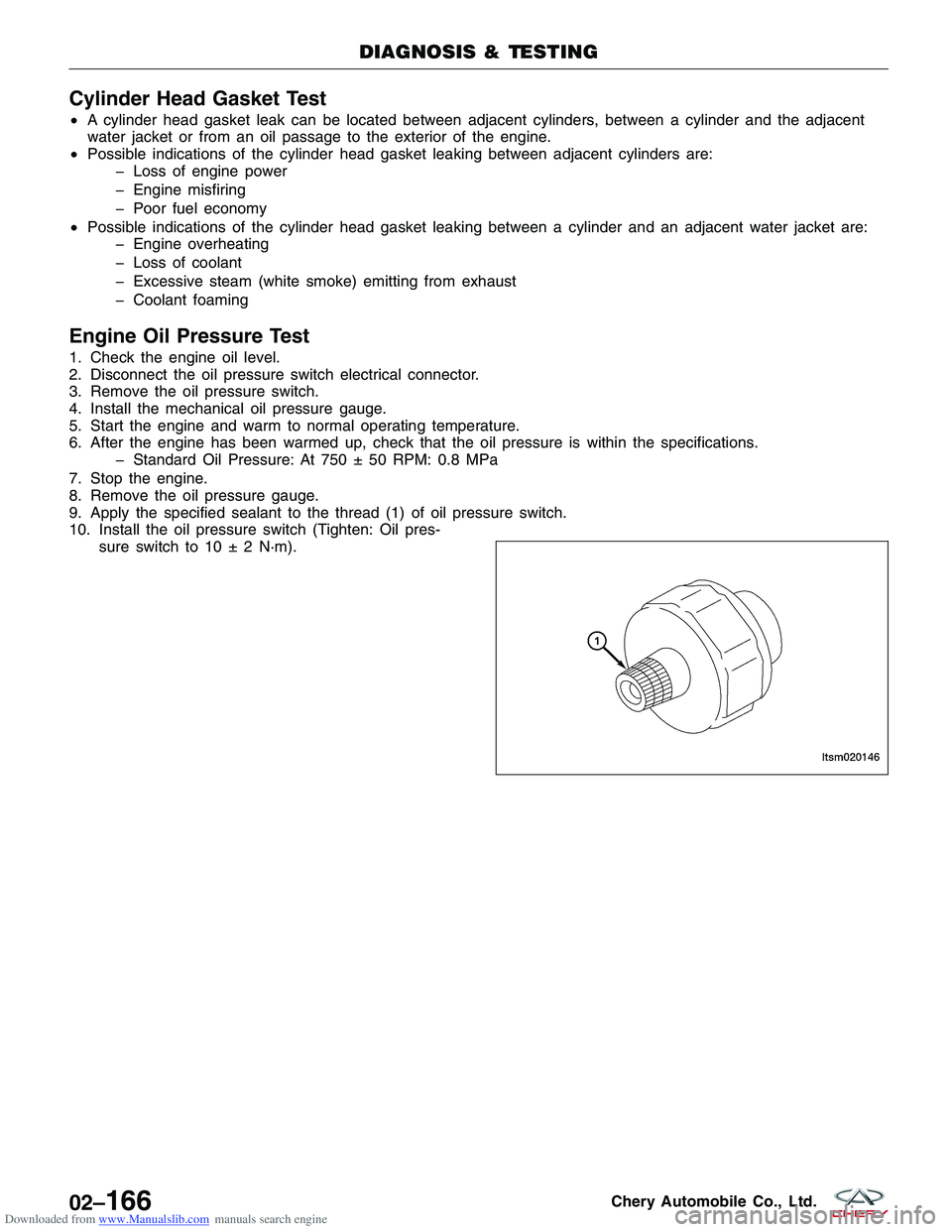
9. Apply the specified sealant to the thread (1) of oil pressure switch.
10. Install the oil pressure switch (Tighten: Oil pres- sure switch to 10 ± 2 N·m).
DIAGNOSIS & TESTING
LTSM020146
02–166Chery Automobile Co., Ltd.
Page 834 of 1903
Downloaded from www.Manualslib.com manuals search engine 4.CHECK FUEL SYSTEM PRESSURE
• Release the fuel system pressure (See Fuel Pressure Relief Procedure in Section 04 Fuel Delivery).
• Check fuel system pressure (See Fuel Pressure Test in Section 04 Fuel Delivery).
Is fuel pressure correct?
Ye s>>Go to the next step.
No
>>If the fuel pressure is greater than 400 kPa (4.0 bar):
� Replace the fuel pressure regulator.
If the fuel pressure is less than 400 kPa (4.0 bar):
� Check the fuel supply system for restrictions or leaks.
� If no problems, repair or replace fuel filter, pressure regulator or fuel pump assembly.
5.CHECK EXHAUST SYSTEM
• Check the exhaust system for restrictions.
Is there a restriction in the exhaust system?
Ye s>>Repair as necessary.
No
>>Go to the next step.
6.CHECK ENGINE OVERHEATING
• Is the engine overheating (hot start concern only)?
For hot start concerns, does engine appear to be overheating?
Ye s>>Repair the engine cooling system.
No
>>Go to the next step.
7.CHECK POSITIVE CRANKCASE VENTILATION (PCV) SYSTEM
• Remove the PCV valve and shake it.
Does PCV valve rattle?
Ye s>>Go to the next step.
No
>>Replace the PCV valve.
ELECTRONIC ENGINE CONTROLS - 2.4L ENGINE SYMPTOM DIAGNOSIS
03–550Chery Automobile Co., Ltd.
Page 836 of 1903
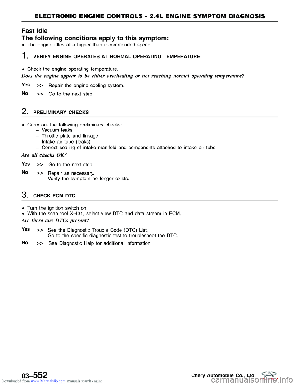
Downloaded from www.Manualslib.com manuals search engine Fast Idle
The following conditions apply to this symptom:
•The engine idles at a higher than recommended speed.
1.VERIFY ENGINE OPERATES AT NORMAL OPERATING TEMPERATURE
• Check the engine operating temperature.
Does the engine appear to be either overheating or not reaching normal operating temperature?
Ye s>>Repair the engine cooling system.
No
>>Go to the next step.
2.PRELIMINARY CHECKS
• Carry out the following preliminary checks:
� Vacuum leaks
� Throttle plate and linkage
� Intake air tube (leaks)
� Correct sealing of intake manifold and components attached to intake air tube
Are all checks OK?
Ye s>>Go to the next step.
No
>>Repair as necessary.
Verify the symptom no longer exists.
3.CHECK ECM DTC
• Turn the ignition switch on.
• With the scan tool X-431, select view DTC and data stream in ECM.
Are there any DTCs present?
Ye s>>See the Diagnostic Trouble Code (DTC) List.
Go to the specific diagnostic test to troubleshoot the DTC.
No
>>See Diagnostic Help for additional information.
ELECTRONIC ENGINE CONTROLS - 2.4L ENGINE SYMPTOM DIAGNOSIS
03–552Chery Automobile Co., Ltd.
Page 918 of 1903
Downloaded from www.Manualslib.com manuals search engine The cooling system regulates engine operating temperature. It allows the engine to reach normal operating temper-
ature as soon as possible, maintains normal operating temperature and prevents overheating.
The cooling system also provides a means of heating the passenger compartment. The cooling system is pressurized
and uses a centrifugal water pump to circulate coolant throughout the system.
The cooling system consists of the following components:
•Radiator
• Coolant
• Coolant pump
• Electric cooling fans
• Electric cooling fans control module
• Thermostat
• Coolant reservoir
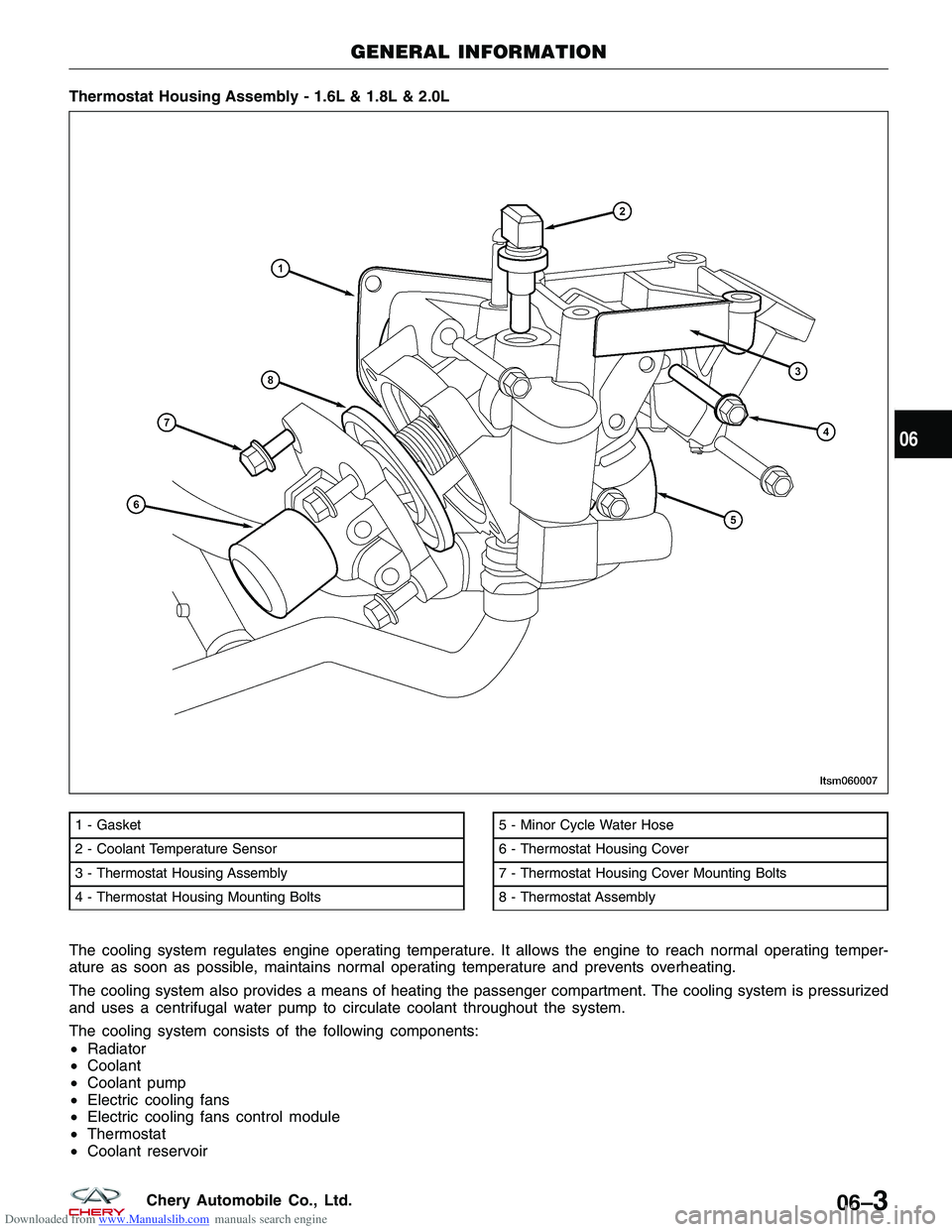
Thermostat Housing Assembly - 1.6L & 1.8L & 2.0L
1 - Gasket
2 - Coolant Temperature Sensor
3 - Thermostat Housing Assembly
4 - Thermostat Housing Mounting Bolts5 - Minor Cycle Water Hose
6 - Thermostat Housing Cover
7 - Thermostat Housing Cover Mounting Bolts
8 - Thermostat Assembly
GENERAL INFORMATION
LTSM060007
06
06–3Chery Automobile Co., Ltd.
Page 928 of 1903
Downloaded from www.Manualslib.com manuals search engine ON-VEHICLE SERVICE
Cooling System Draining and Filling
Cooling System Draining Procedure
WARNING!
Never remove the pressure relief cap, under any conditions, while the engine is operating or hot. Failure to fol-
low these instructions could result in personal injury or damage to the cooling system or engine. To avoid hav-
ing scalding hot coolant or steam blow out of the cooling system, use extreme care when removing the pressure
relief cap. Wait until the engine has cooled, then wrap a thick cloth around the pressure relief cap and turn it
slowly one turn (counterclockwise). Step back while the pressure is released from the cooling system. When you
are certain all the pressure has been released, using a cloth turn and remove the pressure relief cap. Failure to
follow these instructions may result in serious personal injury.
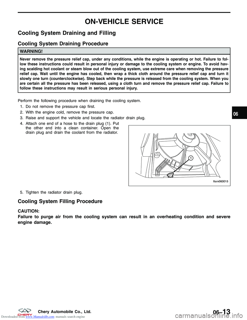
Perform the following procedure when draining the cooling system.1. Do not remove the pressure cap first.
2. With the engine cold, remove the pressure cap.
3. Raise and support the vehicle and locate the radiator drain plug.
4. Attach one end of a hose to the drain plug (1). Put the other end into a clean container. Open the
drain plug and drain the coolant from the radiator.
5. Tighten the radiator drain plug.
Cooling System Filling Procedure
CAUTION:
Failure to purge air from the cooling system can result in an overheating condition and severe
engine damage.
LTSM060015
06
06–13Chery Automobile Co., Ltd.
Page 963 of 1903

Downloaded from www.Manualslib.com manuals search engine NOTE :
Using the TCM electrical harness test tool will help prevent electrical connector terminal damage.
Diagnostic Trouble Code (DTC) List
DP0 Automatic Transaxle DTC List
DTCDTC DEFINITION
P0218 Automatic Transaxle Overheating
P0603 Internal Control Module Memory
P0604 RAM
P0605 Checksum Error
P0641 Sensor Feed
P0657 Solenoid Power Supply Circuit Shorted To Voltage
P0657 SSV Feed Circuit Open
P0705 Multi-function Switch: Prohibited Position
P0706 Multi-function Switch: Intermediate Position
P0709 Multi-function Switch: Affected by Interference
P0710 Fluid Temperature Sensor
P0715 No Turbine Speed Sensor Signal
P0715 Turbine Speed Sensor Affected by Interference
P0720 No Vehicle Speed Sensor Signal
P0720 Vehicle Speed Sensor Affected by Interference
P0720 Vehicle Speed Sensor Signal Consistency
P0730 Cylinder Slip
P0740 Lock-up
P0753 EVS1 Circuit Open
P0753 EVS1 Circuit Shorted To Ground
P0753 EVS1 Circuit Shorted To Voltage
P0758 EVS2 Circuit Open
P0758 EVS2 Circuit Shorted To Voltage
P0763 EVS3 Circuit Open
P0763 EVS3 Circuit Shorted To Voltage
P0768 EVS4 Circuit Open
P0768 EVS4 Circuit Shorted To Ground
P0768 EVS4 Circuit Shorted To Voltage
P0773 EVS5 Circuit Open
P0773 EVS5 Circuit Shorted To Voltage
P0775 EVM (Electronic Valve Modulation) Circuit Open
P0775 EVM (Electronic Valve Modulation) Circuit Shorted To Voltage
P0795 EVLU Circuit Open
P0795 EVLU Shorted To Voltage
P0819 Flick Shift Contact Duration
P0819 Flick Shift Contacts
P0840 Pressure Sensor
P0850 P/N Contact
DIAGNOSIS & TESTING
08–20Chery Automobile Co., Ltd.
Page 1495 of 1903
Downloaded from www.Manualslib.com manuals search engine CONDITIONPOSSIBLE CAUSES CORRECTION
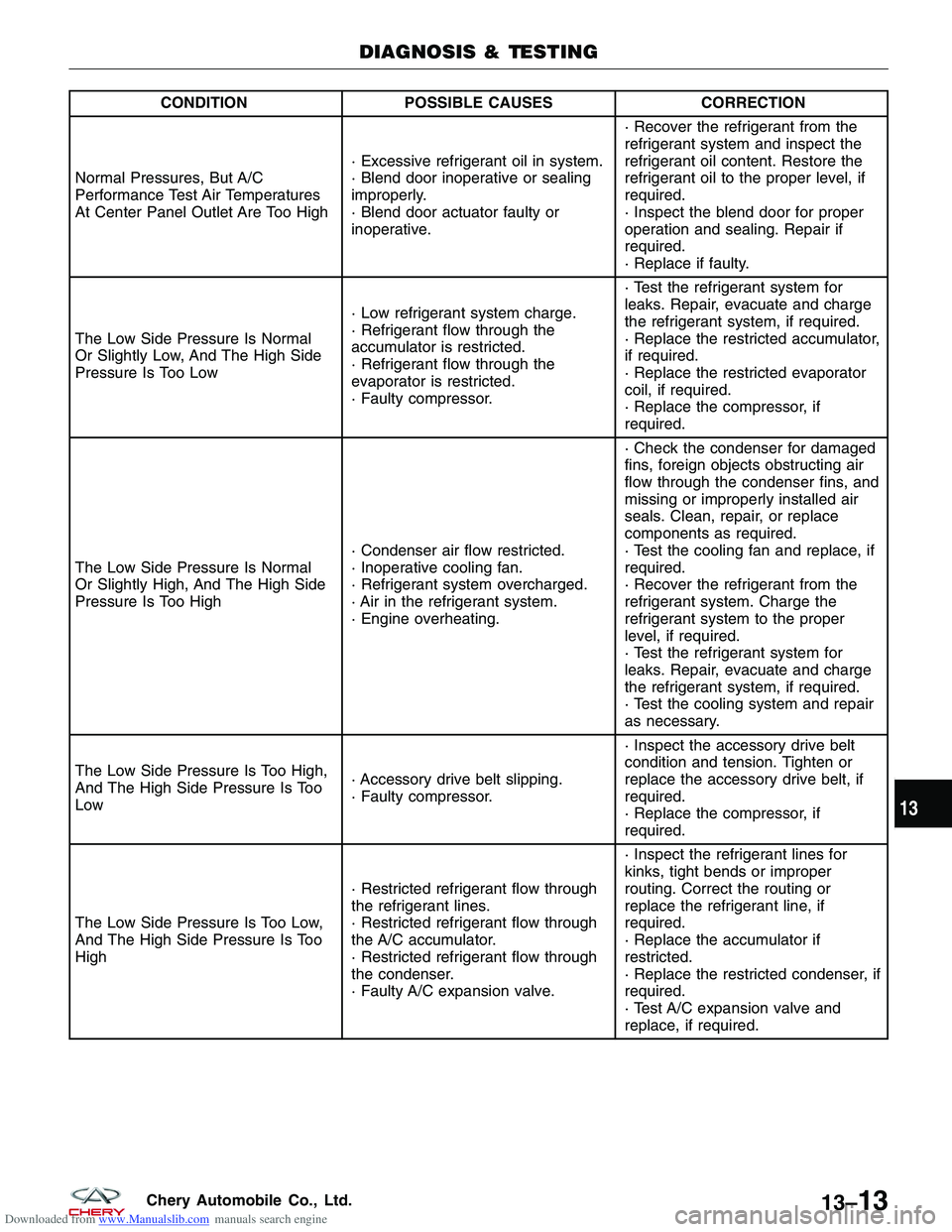
Normal Pressures, But A/C
Performance Test Air Temperatures
At Center Panel Outlet Are Too High · Excessive refrigerant oil in system.
· Blend door inoperative or sealing
improperly.
· Blend door actuator faulty or
inoperative.· Recover the refrigerant from the
refrigerant system and inspect the
refrigerant oil content. Restore the
refrigerant oil to the proper level, if
required.
· Inspect the blend door for proper
operation and sealing. Repair if
required.
· Replace if faulty.
The Low Side Pressure Is Normal
Or Slightly Low, And The High Side
Pressure Is Too Low · Low refrigerant system charge.
· Refrigerant flow through the
accumulator is restricted.
· Refrigerant flow through the
evaporator is restricted.
· Faulty compressor.· Test the refrigerant system for
leaks. Repair, evacuate and charge
the refrigerant system, if required.
· Replace the restricted accumulator,
if required.
· Replace the restricted evaporator
coil, if required.
· Replace the compressor, if
required.
The Low Side Pressure Is Normal
Or Slightly High, And The High Side
Pressure Is Too High · Condenser air flow restricted.
· Inoperative cooling fan.
· Refrigerant system overcharged.
· Air in the refrigerant system.
· Engine overheating.· Check the condenser for damaged
fins, foreign objects obstructing air
flow through the condenser fins, and
missing or improperly installed air
seals. Clean, repair, or replace
components as required.
· Test the cooling fan and replace, if
required.
· Recover the refrigerant from the
refrigerant system. Charge the
refrigerant system to the proper
level, if required.
· Test the refrigerant system for
leaks. Repair, evacuate and charge
the refrigerant system, if required.
· Test the cooling system and repair
as necessary.
The Low Side Pressure Is Too High,
And The High Side Pressure Is Too
Low · Accessory drive belt slipping.
· Faulty compressor.· Inspect the accessory drive belt
condition and tension. Tighten or
replace the accessory drive belt, if
required.
· Replace the compressor, if
required.
The Low Side Pressure Is Too Low,
And The High Side Pressure Is Too
High · Restricted refrigerant flow through
the refrigerant lines.
· Restricted refrigerant flow through
the A/C accumulator.
· Restricted refrigerant flow through
the condenser.
· Faulty A/C expansion valve.· Inspect the refrigerant lines for
kinks, tight bends or improper
routing. Correct the routing or
replace the refrigerant line, if
required.
· Replace the accumulator if
restricted.
· Replace the restricted condenser, if
required.
· Test A/C expansion valve and
replace, if required.
DIAGNOSIS & TESTING
13
13–13Chery Automobile Co., Ltd.