sensor CHEVROLET AVEO 2002 Service Service Manual
[x] Cancel search | Manufacturer: CHEVROLET, Model Year: 2002, Model line: AVEO, Model: CHEVROLET AVEO 2002Pages: 5127, PDF Size: 41.82 MB
Page 2869 of 5127
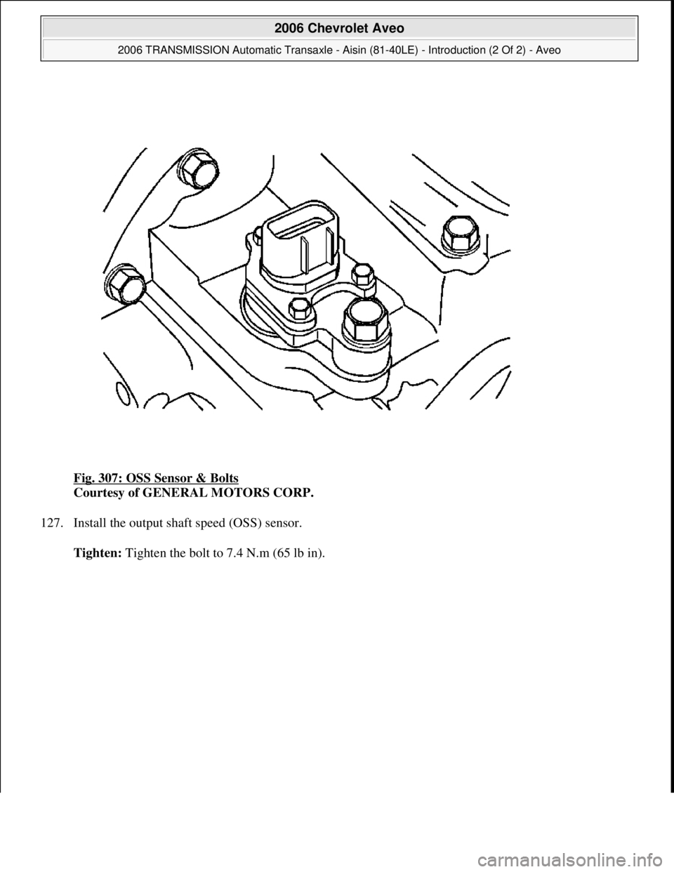
Fig. 307: OSS Sensor & Bolts
Courtesy of GENERAL MOTORS CORP.
127. Install the output shaft speed (OSS) sensor.
Tighten: Ti
ghten the bolt to 7.4 N.m (65 lb in).
2006 Chevrolet Aveo
2006 TRANSMISSION Automatic Transaxle - Aisin (81-40LE) - Introduction (2 Of 2) - Aveo
Microsoft
Thursday, July 16, 2009 1:17:27 PMPage 320 © 2005 Mitchell Repair Information Company, LLC.
Page 2870 of 5127
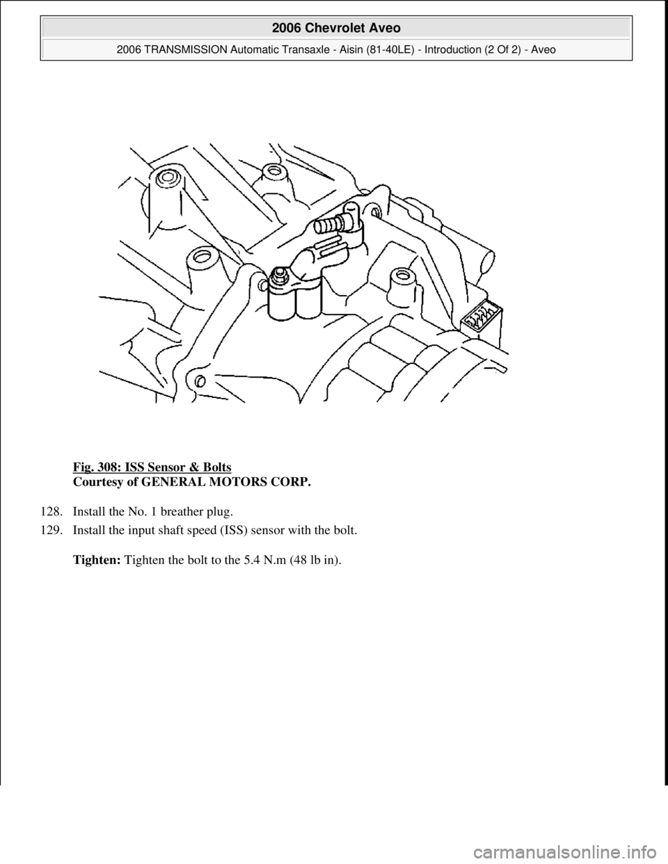
Fig. 308: ISS Sensor & Bolts
Courtesy of GENERAL MOTORS CORP.
128. Install the No. 1 breather plug.
129. Install the input shaft speed (ISS) sensor with the bolt.
Tighten: Tighten the bolt to the 5.4 N.m (48 lb in).
2006 Chevrolet Aveo
2006 TRANSMISSION Automatic Transaxle - Aisin (81-40LE) - Introduction (2 Of 2) - Aveo
Microsoft
Thursday, July 16, 2009 1:17:27 PMPage 321 © 2005 Mitchell Repair Information Company, LLC.
Page 3019 of 5127
ELECTRONIC COMPONENT DESCRIPTION
Transmission Control Module (TCM)
The transmission control module (TCM) primarily controls shift points and lockup engagement. It is located on
the driver side under the instrument panel.
The transmission is controlled by an electronic shift system. The TCM processes input signals. From the
information received, the TCM controls the transmission hydraulic system.
The electronic shift system consists of the following components.
TCM
Shift solenoids (SS1 and SS2)
Pressure control solenoid (PCS)
Lockup solenoid
Input shaft speed (ISS) sensor
Output shaft speed (OSS) sensor
Transmission fluid temperature (TFT) sensor
Park/neutral position (PNP) switch
Park/Neutral Position (PNP) Switch
The PNP switch transmits the information which range includes the shift lever of the automatic transmission
(A/T) to the starter and TCM.
It is possible for the PNP switch to start an engine in only park (P) and neutral (N) prevention of reckless
driving
The PNP switch makes the backup lamp turn on when reversing.
It is used for PNP switch to shift control.
The PNP switch transmits the information by combination of starter and reverse circuit to the vehicle side
directl
y without TCM.
2006 Chevrolet Aveo
2006 TRANSMISSION Automatic Transaxle - Aisin (81-40LE) - Introduction (2 Of 2) - Aveo
Microsoft
Thursday, July 16, 2009 1:17:34 PMPage 470 © 2005 Mitchell Repair Information Company, LLC.
Page 3025 of 5127
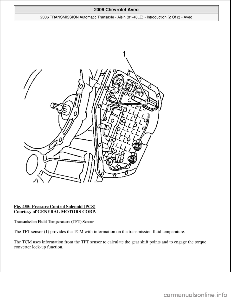
Fig. 455: Pressure Control Solenoid (PCS)
Courtesy of GENERAL MOTORS CORP.
Transmission Fluid Temperature (TFT) Sensor
The TFT sensor (1) provides the TCM with information on the transmission fluid temperature.
The TCM uses information from the TFT sensor to calculate the gear shift points and to engage the torque
converter loc
k-up function.
2006 Chevrolet Aveo
2006 TRANSMISSION Automatic Transaxle - Aisin (81-40LE) - Introduction (2 Of 2) - Aveo
Microsoft
Thursday, July 16, 2009 1:17:34 PMPage 476 © 2005 Mitchell Repair Information Company, LLC.
Page 3026 of 5127
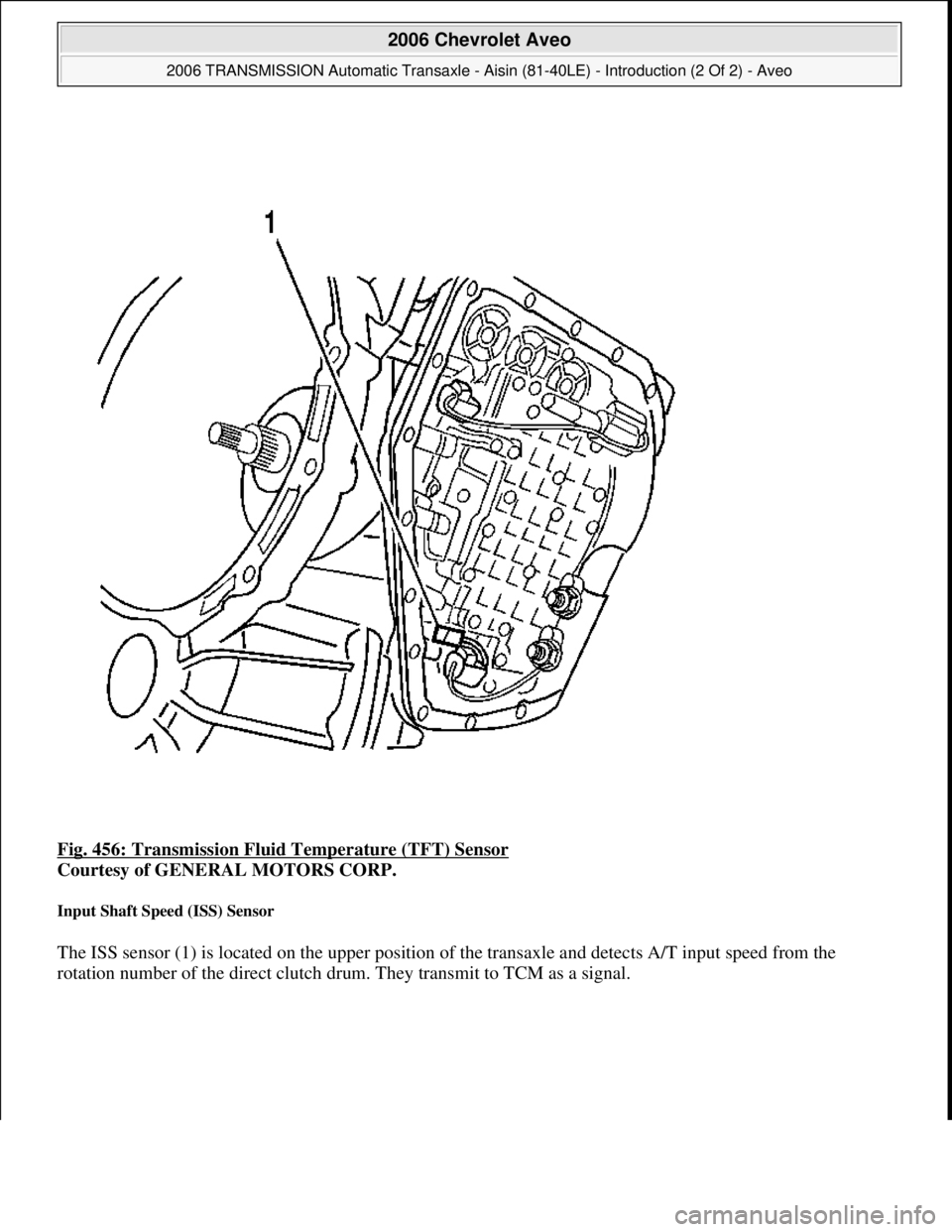
Fig. 456: Transmission Fluid Temperature (TFT) Sensor
Courtesy of GENERAL MOTORS CORP.
Input Shaft Speed (ISS) Sensor
The ISS sensor (1) is located on the upper position of the transaxle and detects A/T input speed from the
rotation number of the direct clutch drum. They transmit to TCM as a signal.
2006 Chevrolet Aveo
2006 TRANSMISSION Automatic Transaxle - Aisin (81-40LE) - Introduction (2 Of 2) - Aveo
Microsoft
Thursday, July 16, 2009 1:17:34 PMPage 477 © 2005 Mitchell Repair Information Company, LLC.
Page 3027 of 5127
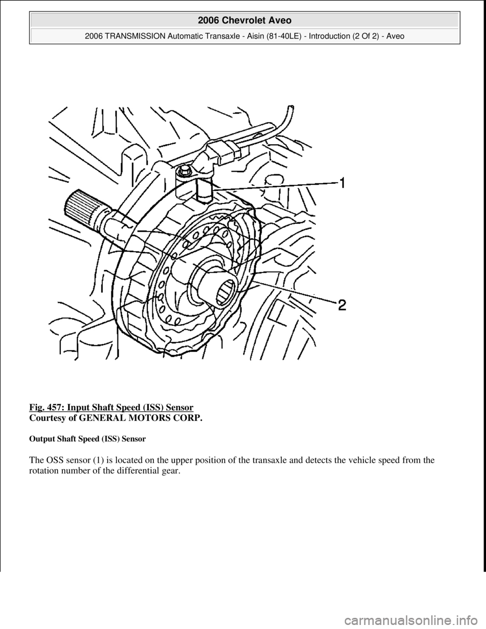
Fig. 457: Input Shaft Speed (ISS) Sensor
Courtesy of GENERAL MOTORS CORP.
Output Shaft Speed (ISS) Sensor
The OSS sensor (1) is located on the upper position of the transaxle and detects the vehicle speed from the
rotation number of the differential
gear.
2006 Chevrolet Aveo
2006 TRANSMISSION Automatic Transaxle - Aisin (81-40LE) - Introduction (2 Of 2) - Aveo
Microsoft
Thursday, July 16, 2009 1:17:34 PMPage 478 © 2005 Mitchell Repair Information Company, LLC.
Page 3028 of 5127
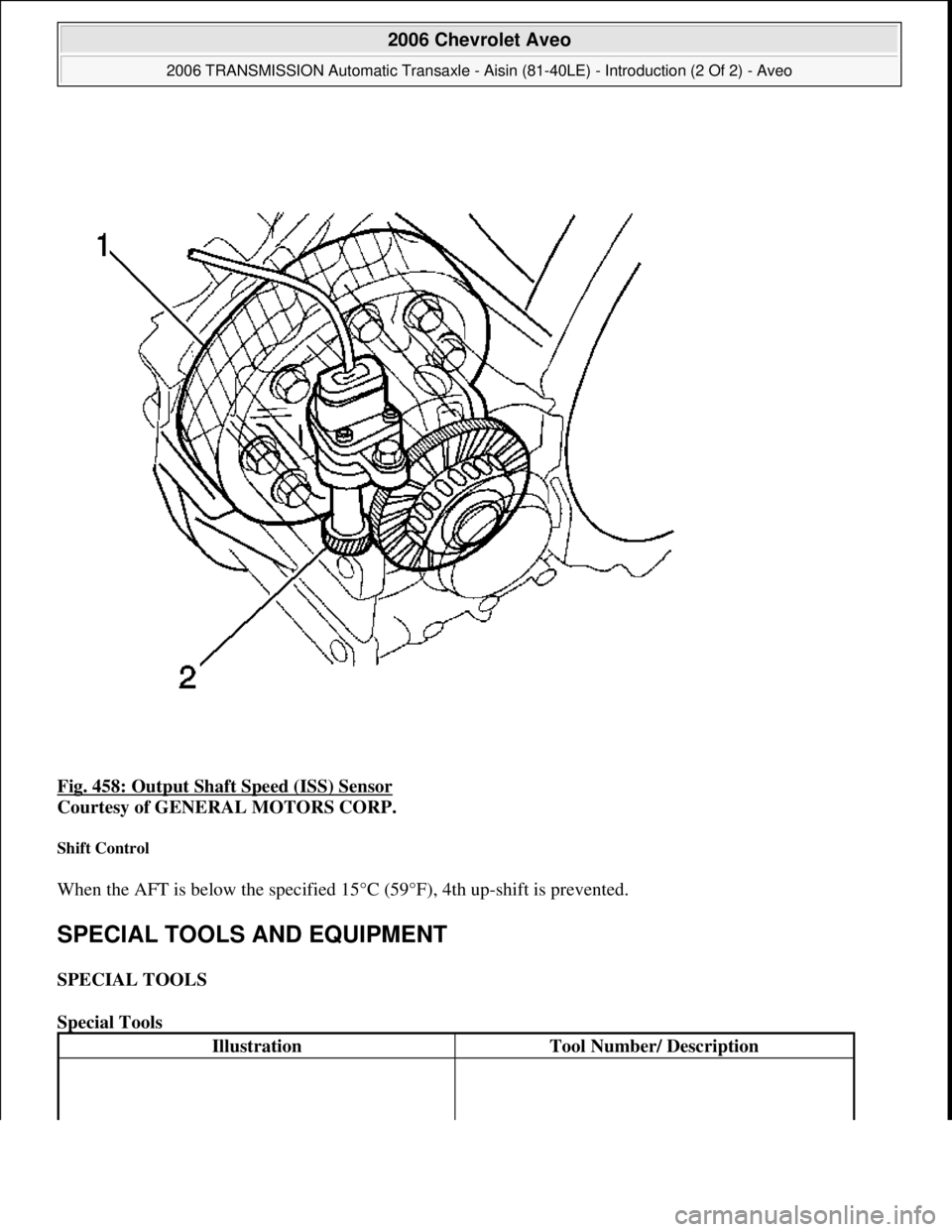
Fig. 458: Output Shaft Speed (ISS) Sensor
Courtesy of GENERAL MOTORS CORP.
Shift Control
When the AFT is below the specified 15°C (59°F), 4th up-shift is prevented.
SPECIAL TOOLS AND EQUIPMENT
SPECIAL TOOLS
Special Tools
IllustrationTool Number/ Description
2006 Chevrolet Aveo
2006 TRANSMISSION Automatic Transaxle - Aisin (81-40LE) - Introduction (2 Of 2) - Aveo
Microsoft
Thursday, July 16, 2009 1:17:34 PMPage 479 © 2005 Mitchell Repair Information Company, LLC.
Page 4304 of 5127
Multifunction Alarm Module
Connector Part InformationKET MG 611336
26-Way F PCB Connector (WH)
PinWire ColorCircuit No.Function
1WH30Fuel Level Sensor Signal
2D-GN/WH817Vehicle Speed Signal
3WH121Engine Speed Signal
4WH135Engine Coolant Temperature (ECT) Sensor
Gauge Signal
5PU172Low Fuel Indicator Control
6BN33Brake Warning Indicator Control
7WH15Right Turn Signal Lamps Supply Voltage
8GY/D-GN11Headlamp High Beam Supply Voltage
9D-BU14Left Turn Signal Lamps Supply Voltage
10OG640Battery Positive Voltage
11PK239Ignition 1 Voltage
12BN/WH309Right Park Lamp Supply Voltage
13
BK450Ground (w/o Dimming)
L-GN/RD230Instrument Panel Lamps Dimming Control
(w/Dimming)
14BK450Ground
15-16--Not Used
17D-BU25Charge Indicator Control/Charge Indicator
Signal (w/o Tach)
18BN/BK419Malfunction Indicator Lamp (MIL) Control
(w/o Tach)
19D-G31Oil Pressure Indicator Control (w/o Tach)
20BK/WH238Seat Belt Switch - Driver (w/o Tach)
21WH629Daytime Running Lamp (DRL) On Indicator
Control (w/o Tach)
22L-BU122Rear Fog Lamp Supply Voltage (w/o Tach)
23D-GN/WH358Air Bag Indicator Control (w/o Tach)
24OG640Battery Positive Voltage (w/o Tach)
25D-GN/WH157Courtesy Lamp Control (w/o Tach)
26BK450Ground
2005 Chevrolet Aveo
2005 ACCESSORIES & EQUIPMENT Instrument Panel, Gages, & Console - Aveo
Microsoft
Friday, July 31, 2009 1:07:02 PMPage 11 © 2005 Mitchell Repair Information Company, LLC.
Page 4307 of 5127
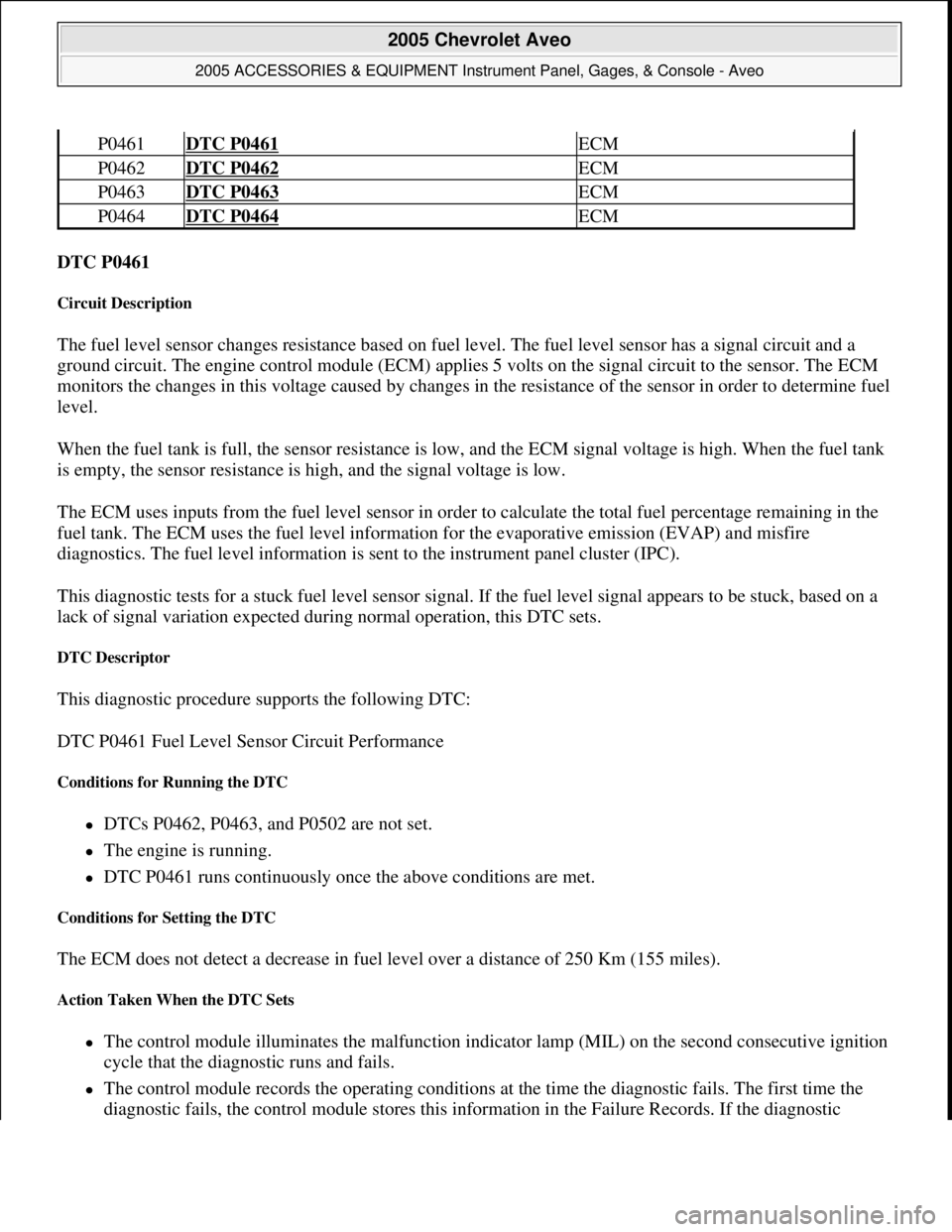
DTC P0461
Circuit Description
The fuel level sensor changes resistance based on fuel level. The fuel level sensor has a signal circuit and a
ground circuit. The engine control module (ECM) applies 5 volts on the signal circuit to the sensor. The ECM
monitors the changes in this voltage caused by changes in the resistance of the sensor in order to determine fuel
level.
When the fuel tank is full, the sensor resistance is low, and the ECM signal voltage is high. When the fuel tank
is empty, the sensor resistance is high, and the signal voltage is low.
The ECM uses inputs from the fuel level sensor in order to calculate the total fuel percentage remaining in the
fuel tank. The ECM uses the fuel level information for the evaporative emission (EVAP) and misfire
diagnostics. The fuel level information is sent to the instrument panel cluster (IPC).
This diagnostic tests for a stuck fuel level sensor signal. If the fuel level signal appears to be stuck, based on a
lack of signal variation expected during normal operation, this DTC sets.
DTC Descriptor
This diagnostic procedure supports the following DTC:
DTC P0461 Fuel Level Sensor Circuit Performance
Conditions for Running the DTC
DTCs P0462, P0463, and P0502 are not set.
The engine is running.
DTC P0461 runs continuously once the above conditions are met.
Conditions for Setting the DTC
The ECM does not detect a decrease in fuel level over a distance of 250 Km (155 miles).
Action Taken When the DTC Sets
The control module illuminates the malfunction indicator lamp (MIL) on the second consecutive ignition
cycle that the diagnostic runs and fails.
The control module records the operating conditions at the time the diagnostic fails. The first time the
dia
gnostic fails, the control module stores this information in the Failure Records. If the diagnostic
P0461DTC P0461 ECM
P0462DTC P0462 ECM
P0463DTC P0463 ECM
P0464DTC P0464 ECM
2005 Chevrolet Aveo
2005 ACCESSORIES & EQUIPMENT Instrument Panel, Gages, & Console - Aveo
Microsoft
Friday, July 31, 2009 1:07:02 PMPage 14 © 2005 Mitchell Repair Information Company, LLC.
Page 4308 of 5127
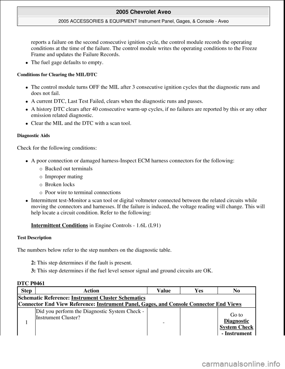
reports a failure on the second consecutive ignition cycle, the control module records the operating
conditions at the time of the failure. The control module writes the operating conditions to the Freeze
Frame and updates the Failure Records.
The fuel gage defaults to empty.
Conditions for Clearing the MIL/DTC
The control module turns OFF the MIL after 3 consecutive ignition cycles that the diagnostic runs and
does not fail.
A current DTC, Last Test Failed, clears when the diagnostic runs and passes.
A history DTC clears after 40 consecutive warm-up cycles, if no failures are reported by this or any other
emission related diagnostic.
Clear the MIL and the DTC with a scan tool.
Diagnostic Aids
Check for the following conditions:
A poor connection or damaged harness-Inspect ECM harness connectors for the following:
Backed out terminals
Improper mating
Broken locks
Poor wire to terminal connections
Intermittent test-Monitor a scan tool or digital voltmeter connected between the related circuits while
moving the connectors and harnesses. If the failure is induced, the voltage reading will change. This will
help locate a circuit condition. Refer to the following:
Intermittent Conditions
in Engine Controls - 1.6L (L91)
Test Description
The numbers below refer to the step numbers on the diagnostic table.
2: This step determines if the fault is present.
3: This step determines if the fuel level sensor signal and ground circuits are OK.
DTC P0461
StepActionValueYesNo
Schematic Reference: Instrument Cluster Schematics
Connector End View Reference: Instrument Panel, Gages, and Console Connector End Views
1
Did you perform the Diagnostic System Check -
Instrument Cluster?
-
Go to
Diagnostic
System Check
- Instrument
2005 Chevrolet Aveo
2005 ACCESSORIES & EQUIPMENT Instrument Panel, Gages, & Console - Aveo
Microsoft
Friday, July 31, 2009 1:07:02 PMPage 15 © 2005 Mitchell Repair Information Company, LLC.