CHEVROLET BLAZER 2003 2.G Owners Manual
Manufacturer: CHEVROLET, Model Year: 2003, Model line: BLAZER, Model: CHEVROLET BLAZER 2003 2.GPages: 420, PDF Size: 2.94 MB
Page 121 of 420
To reset the trip computer, press the MODE and
US/MET buttons simultaneously for at least two
seconds. All functions will be displayed brie¯y once the
system is reset. Reset can only be performed in the
AVG ECON, FUEL USED and AVG SPEED modes. All
three modes are reset at the same time.
Front Storage Area
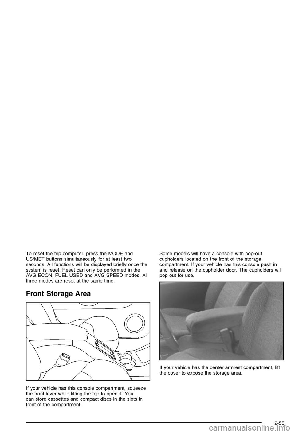
If your vehicle has this console compartment, squeeze
the front lever while lifting the top to open it. You
can store cassettes and compact discs in the slots in
front of the compartment.Some models will have a console with pop-out
cupholders located on the front of the storage
compartment. If your vehicle has this console push in
and release on the cupholder door. The cupholders will
pop out for use.
If your vehicle has the center armrest compartment, lift
the cover to expose the storage area.
2-55
Page 122 of 420
Assist Handles
Use the assist handle above each passenger door
when getting out of your vehicle.
Garment Hooks
Vehicle Location
Two-Door Utility On the headiners above
the passenger door, both
rear outboard passenger
seats, and passenger side
trim panel
Four-Door Utility Four on the headliner in
the rear of the vehicle
Luggage Carrier
{CAUTION:
If you try to carry something on top of your
vehicle that is longer or wider than the luggage
carrier Ð like paneling, plywood, a mattress
and so forth Ð the wind can catch it as you
drive along. This can cause you to lose
control. What you are carrying could be
violently torn off, and this could cause you or
other drivers to have a collision, and of course
damage your vehicle. You may be able to carry
something like this inside. But, never carry
something longer or wider than the luggage
carrier on top of your vehicle.
If your vehicle is equipped with a luggage carrier, it may
have side rails and crossrails attached to the roof to
secure cargo. The adjustable tie downs, at both ends of
the crossrails, should be used to secure loads to the
luggage carrier. Use GM accessory racks that are
compatible with your luggage carrier for transporting
sports equipment. These are available through
your dealer.
2-56
Page 123 of 420
You can adjust the crossrails to handle loads of various
sizes. Just loosen the slider knobs at each end of
the crossrail and move them to where you want them.
Make sure both sides of the crossrails are even,
then tighten the slider knobs.
Be sure the cargo is properly loaded. Follow these
guidelines:
·Carrying small, heavy loads on the roof is not
recommended.
·Secure the load using the tie downs at both ends of
the crossrails. When loading cargo directly on the
roof panel, use the crossrails to keep the load from
shifting.
·If you need to carry long items, move the crossrails
as far apart as possible. Tie the load to the tie
downs provided. Also tie the load to the bumpers.
Do not tie the load so tightly that the crossrails
or side rails are damaged.
Notice:Loading cargo that weighs more than
200 lbs. (91 kg) on the luggage carrier may damage
your vehicle. When you carry large things, never
let them hang over the rear or the sides of your
vehicle. Load your cargo so that it rests on the slats
and does not scratch or damage the vehicle. Put
the cargo against the side rails and fasten it
securely to the luggage carrier. Put the main weight
as far forward as you can.Don't exceed the maximum vehicle capacity when
loading your vehicle. For more information on vehicle
capacity and loading see
Loading Your Vehicle on
page 4-52.
To prevent damage or loss of cargo as you're driving,
check now and then to make sure the luggage
carrier and cargo are still securely fastened.
Convenience Net
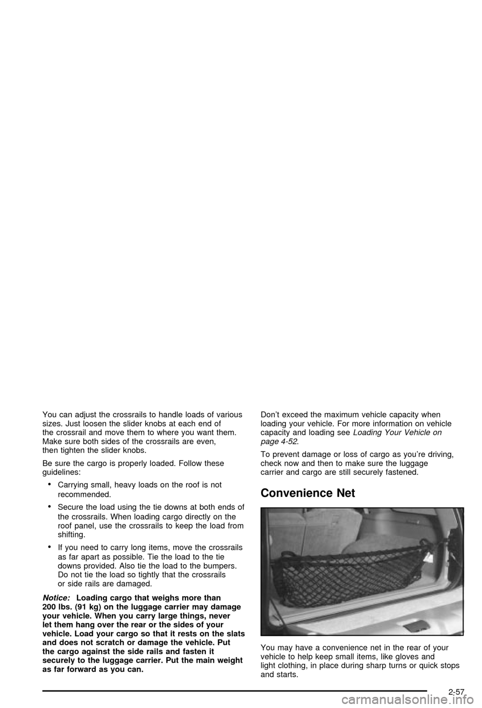
You may have a convenience net in the rear of your
vehicle to help keep small items, like gloves and
light clothing, in place during sharp turns or quick stops
and starts.
2-57
Page 124 of 420
The net is not designed to retain these items during
off-road use. The net is not for larger, heavier items.
Attach the upper loops to the retainers on both sides of
the tailgate opening. The label should be in the upper
passenger's side corner, visible from the rear of vehicle.
Attach the lower hooks to the rear cargo tie-downs on
the ¯oor.
Cargo Cover
If your vehicle has a cargo cover, you can use it to
cover items in the cargo area of your vehicle.
Grasp the handle and unroll the cover. Latch the posts
into the sockets on the inside trim panel on the
passenger's side of the vehicle to secure it.
{CAUTION:
An improperly stored cargo cover could be
thrown about the vehicle during a collision or
sudden maneuver. You or others could be
injured. If you remove the cover, always store
it in the proper storage location. When you put
it back, always be sure that it is securely
reattached.
Cargo Tie-Downs
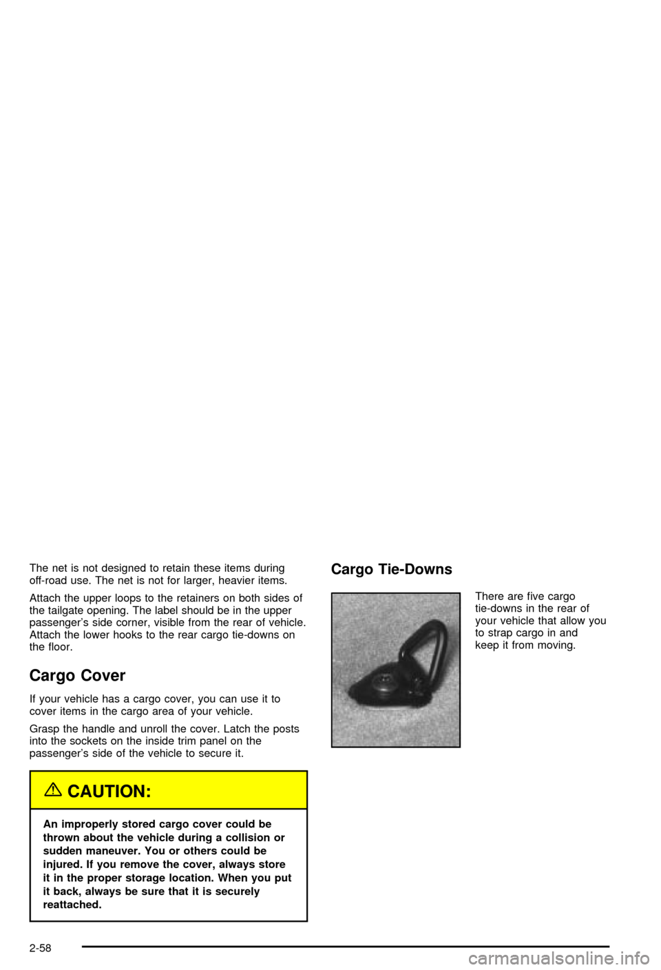
There are ®ve cargo
tie-downs in the rear of
your vehicle that allow you
to strap cargo in and
keep it from moving.
2-58
Page 125 of 420
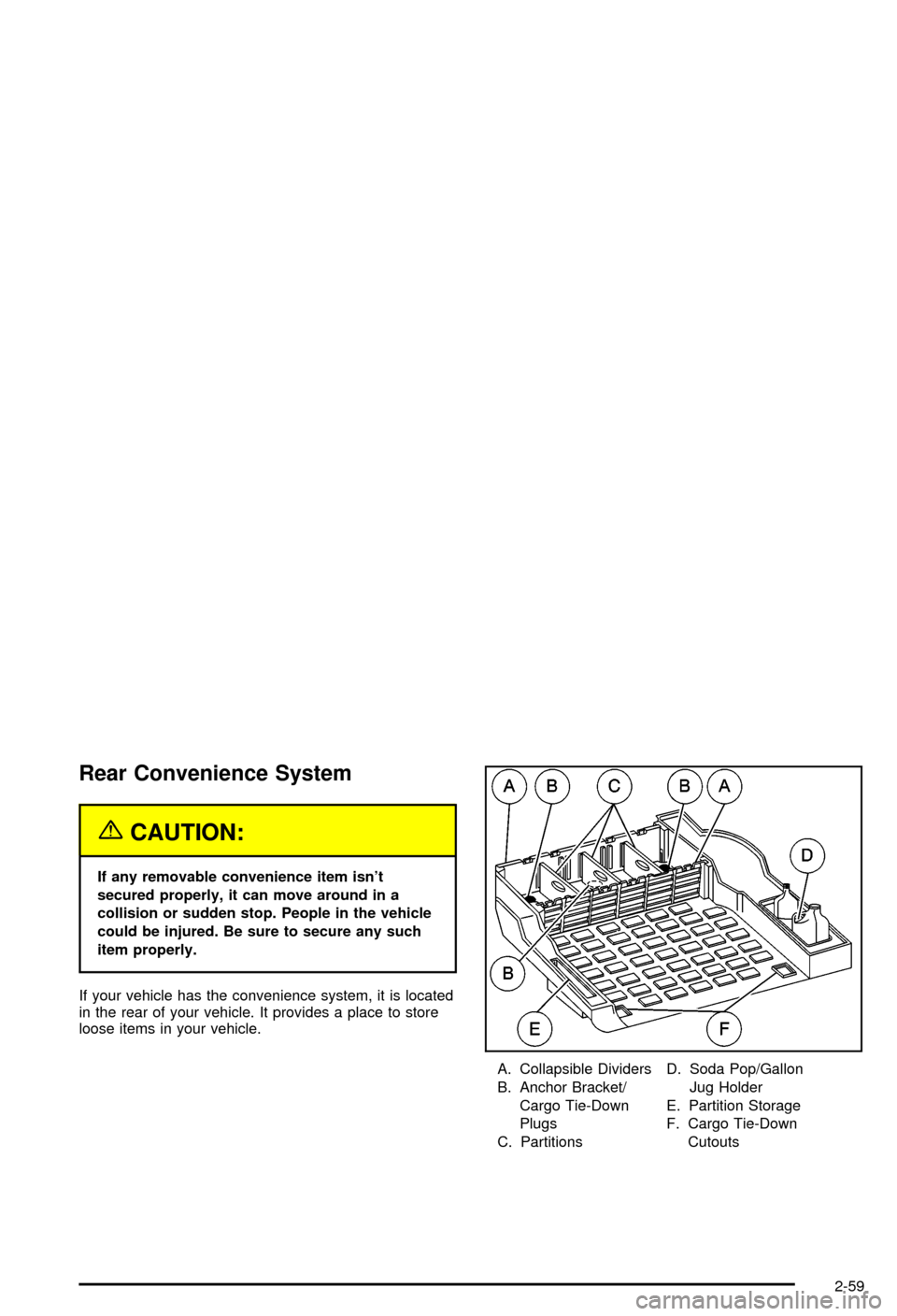
Rear Convenience System
{CAUTION:
If any removable convenience item isn't
secured properly, it can move around in a
collision or sudden stop. People in the vehicle
could be injured. Be sure to secure any such
item properly.
If your vehicle has the convenience system, it is located
in the rear of your vehicle. It provides a place to store
loose items in your vehicle.
A. Collapsible Dividers
B. Anchor Bracket/
Cargo Tie-Down
Plugs
C. PartitionsD. Soda Pop/Gallon
Jug Holder
E. Partition Storage
F. Cargo Tie-Down
Cutouts
2-59
Page 126 of 420

To increase the space in the convenience system, do
the following:
1. Pull up on the individual partitions (C) to
remove them.. Storage for the partitions is located
in area (E).
2. Fold the collapsible dividers (A) by pulling upward
and folding the dividers toward each other.
To reinstall or rearrange the partitions, push down
gently on the partitions making sure both sides ®t into
the appropriate slots of the collapsible dividers (A).
Located on the top of each collapsible divider (A) are
T-pins designed to hold grocery bags, etc., in an upright
position.
The anchor bracket/cargo tie down plugs (B), located in
the center and on each side of the convenience
system nearest the passenger compartment, are used
to help seal the convenience system. However, the
plugs also cover the anchor bracket/cargo tie-downs. To
remove the plugs, grasp the edges of the plugs and
pull straight out. See
Child Restraint Systems on
page 1-38andTop Strap on page 1-42for more
information on using anchor brackets.There are two cutouts (F) for the rear cargo tie-downs
located near the tailgate sill. In order to access the rear
cargo tie-downs, the cutouts must be removed.
You will also ®nd a soda pop/gallon jug holder (D) on
the passenger side of the convenience system.
Some vehicles do not have this feature, but instead
include a smaller storage area.
To remove the entire convenience system, do the
following:
1. Remove the convenience net if it is in place. See
Convenience Net on page 2-57for more
information. You may also want to remove the
partitions (C) and fold the collapsible dividers (A) to
make the convenience system easier to handle.
2. Grasp the sides of the convenience system and
push the sides together while sliding the unit out
until it clears the sides of the tailgate opening.
To reinstall the convenience system, reverse the
removal procedure.
2-60
Page 127 of 420

Vehicle Personalization
Memory Seat
If your vehicle has this
feature, the control located
on the outboard side of
the driver's seat looks
like this.
Use this memory function to save your seat cushion and
seatback settings by using the following procedure:
1. Adjust the driver's seat to a safe and comfortable
driving position.
2. Press the SET button and then press and hold
button 1 (for Driver 1) for three seconds. A chime will
sound to let you know that the position has been
stored.
A second seating can be programmed by repeating
the procedure with a second driver and pressing
button 2 for three seconds.When your vehicle is in PARK (P) for an automatic
transmission or the parking brake is engaged for
a manual transmission, press and release the numbered
memory button you just stored. The seat will move to
the set position. You will hear one chime.
Pressing the UNLOCK button of a keyless entry
transmitter will adjust the seat to the corresponding
stored memory position. You will hear one chime.
Repeat Steps 1 and 2 to readjust the seat. The
transmitter need not be reprogrammed unless it needs
to correspond to the other numbered memory button.
If there is a third driver, use the seat adjuster switch to
adjust the seat.
Pressing any of the seat adjuster switches, the SET
button or pressing the desired memory button twice will
cause the seat to stop moving.
If you press the numbered button to adjust the seat and
start the vehicle while the seat is still adjusting,
adjustment will pause while the ignition is in START.
Adjustment will resume after the ignition is in RUN.
Setting the seat memory function for a particular driver
will also personalize the radio station presets that have
been selected. Each time the driver sets this function, the
respective radio station presets will also be retained.
2-61
Page 128 of 420

-NOTES
2-62
Page 129 of 420

Instrument Panel Overview...............................3-2
Hazard Warning Flashers................................3-3
Other Warning Devices...................................3-4
Horn.............................................................3-4
Tilt Wheel.....................................................3-4
Turn Signal/Multifunction Lever.........................3-5
Exterior Lamps.............................................3-11
Interior Lamps..............................................3-14
Accessory Power Outlets...............................3-15
Ashtrays and Cigarette Lighter........................3-16
Climate Controls............................................3-17
Climate Control System.................................3-17
Outlet Adjustment.........................................3-20
Warning Lights, Gages and Indicators.............3-21
Instrument Panel Cluster................................3-22
Speedometer and Odometer...........................3-24
Trip Odometer..............................................3-24
Tachometer.................................................3-24
Safety Belt Reminder Light.............................3-25
Air Bag Readiness Light................................3-25
Charging System Light..................................3-26
Voltmeter Gage............................................3-27
Up-Shift Light...............................................3-27
Brake System Warning Light..........................3-28
Anti-Lock Brake System Warning Light.............3-29
Engine Coolant Temperature Gage..................3-29Malfunction Indicator Lamp.............................3-30
Oil Pressure Gage........................................3-33
Security Light...............................................3-34
Service Four-Wheel Drive Warning Light..........3-34
Tow/Haul Mode Light....................................3-35
Check Gages Warning Light...........................3-35
Gate Ajar Light.............................................3-35
Fuel Gage...................................................3-35
Low Fuel Warning Light.................................3-36
Audio System(s).............................................3-37
Setting the Time for Radios without Radio
Data Systems (RDS)..................................3-37
Setting the Time for Radios with Radio Data
Systems (RDS).........................................3-38
AM-FM Radio...............................................3-38
Radio with CD..............................................3-41
Radio with Cassette and CD..........................3-48
Radio with Six-Disc CD.................................3-58
Theft-Deterrent Feature (Non-RDS Radios).......3-68
Theft-Deterrent Feature (RDS Radios).............3-68
Understanding Radio Reception......................3-69
Care of Your Cassette Tape Player.................3-69
Care of Your CDs.........................................3-70
Care of Your CD Player................................3-70
Fixed Mast Antenna......................................3-70
Section 3 Instrument Panel
3-1
Page 130 of 420

Instrument Panel Overview
The main components of your instrument panel are the following:
3-2