check engine CHEVROLET CAMARO 1967 1.G Chassis Workshop Manual
[x] Cancel search | Manufacturer: CHEVROLET, Model Year: 1967, Model line: CAMARO, Model: CHEVROLET CAMARO 1967 1.GPages: 659, PDF Size: 114.24 MB
Page 622 of 659

ACCESSORIES 15-13
SYSTEM TEST
CHECKS AND ADJUSTMENTS
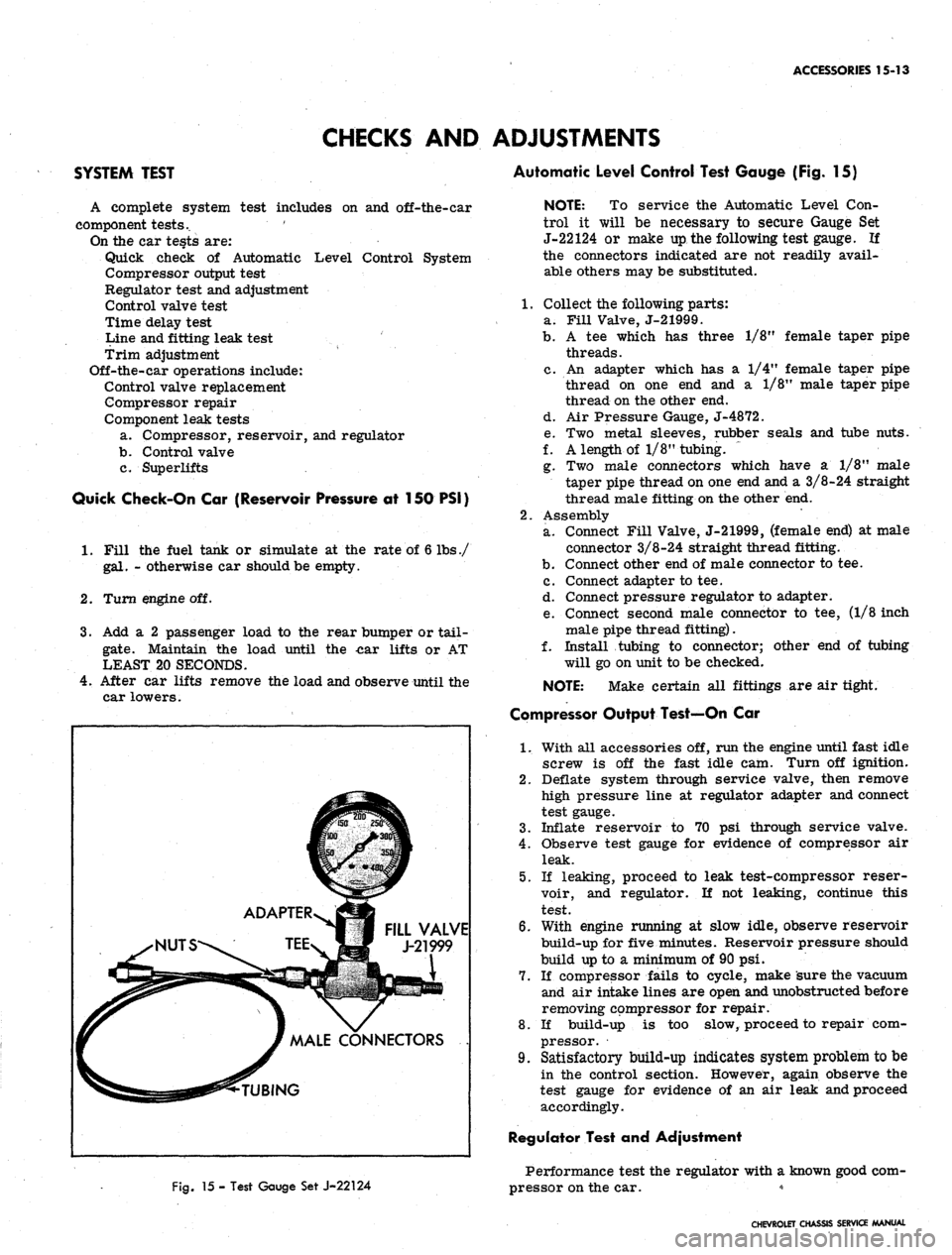
Automatic Level Control Test Gauge (Fig. 15)
A complete system test includes on and off-the-car
component tests.. '
On the car tests are:
Quick check of Automatic Level Control System
Compressor output test
Regulator test and adjustment
Control valve test
Time delay test
Line and fitting leak test
Trim adjustment
Off-the-car operations include:
Control valve replacement
Compressor repair
Component leak tests
a. Compressor, reservoir, and regulator
b.
Control valve
c. Superlifts
Quick Check-On Car (Reservoir Pressure at 150 PSI)
1.
Fill the fuel tank or simulate at the rate of 6 lbs./
gal.
- otherwise car should be empty.
2.
Turn engine off.
3.
Add a 2 passenger load to the rear bumper or tail-
gate.
Maintain the load until the -car lifts or AT
LEAST 20 SECONDS.
4.
After car lifts remove the load and observe until the
car lowers.
FILL VALVE
J-21999
CONNECTORS
Fig.
15 - Test Gauge Set J-22124
NOTE: To service the Automatic Level Con-
trol it will be necessary to secure Gauge Set
J-22124 or make up the following test gauge. If
the connectors indicated are not readily avail-
able others may be substituted.
1.
Collect the following parts:
a. Fill Valve, J-21999.
b.
A tee which has three 1/8M female taper pipe
threads.
c. An adapter which has a 1/4" female taper pipe
thread on one end and a 1/8" male taper pipe
thread on the other end.
d. Air Pressure Gauge, J-4872.
e. Two metal sleeves, rubber seals and tube nuts.
f. A length of 1/8" tubing. ~
g. Two male connectors which have a 1/8" male
taper pipe thread on one end and a 3/8-24 straight
thread male fitting on the other end.
2.
Assembly
a. Connect Fill Valve, J-21999, (female end) at male
connector 3/8-24 straight thread fitting.
b.
Connect other end of male connector to tee.
c. Connect adapter to tee.
d. Connect pressure regulator to adapter.
e. Connect second male connector to tee, (1/8 inch
male pipe thread fitting).
f. Install tubing to connector; other end of tubing
will go on unit to be checked.
NOTE:
Make certain all fittings are air tight.
Compressor Output Test—On Car
1.
With all accessories off, run the engine until fast idle
screw is off the fast idle cam. Turn off ignition.
2.
Deflate system through service valve, then remove
high pressure line at regulator adapter and connect
test gauge.
3.
Inflate reservoir to 70 psi through service valve.
4.
Observe test gauge for evidence of compressor air
leak.
5.
If leaking, proceed to leak test-compressor reser-
voir, and regulator. If not leaking, continue this
test.
6. With engine running at slow idle, observe reservoir
build-up for five minutes. Reservoir pressure should
build up to a minimum of 90 psi.
7.
If compressor fails to cycle, make sure the vacuum
and air intake lines are open and unobstructed before
removing compressor for repair.
8. If build-up is too slow, proceed to repair com-
pressor.
9. Satisfactory build-up indicates system problem to be
in the control section. However, again observe the
test gauge for evidence of an air leak and proceed
accordingly.
Regulator Test and Adjustment
Performance test the regulator with a known good com-
pressor on the car. *
CHEVROLET CHASSIS SERVICE MANUAL
Page 623 of 659

ACCESSORIES 15-14
Deflate system through service valve and disconnect
line at pressure regulator valve. Install test gauge on
regulator valve high pressure fitting.
Inflate system through service valve to maximum
available pressure.
NOTE: If available pressure is less than 140
psi,
start engine to build-up reservoir to this
pressure.
Regulated pressure should build-up to and hold
steady at 100-130 psi on test gauge.
Check regulated pressure by momentarily (not more
than one second) depressing valve core on test gauge
arid observe gauge reading.
If regulated pressure now reads less than 100 psi,
replace regulator assembly.
If regulated pressure exceeds 130 psi, replace regu-
lator assembly.
Control Valve Test
Exhaust (Superlifts Inflated)
1.
Disconnect control valve lever from link.
2.
Hold lever down in exhaust position until Superlifts
deflate or for a minimum of 18 seconds.
3.
If Superlifts deflate, perform Intake Check.
4.
If Superlifts do not deflate, remove exhaust adapter
from control valve and hold lever down as in Step 2.
Replace adapter, O-ring and filter if this deflates
Superlifts.
5.
Replace control valve if none of the above steps solve
problem.
Intake (Reservoir Pressure 125 psi Minimum)
1.
Disconnect overtravel lever from link.
2.
Hold lever up in intake position until Superlifts in-
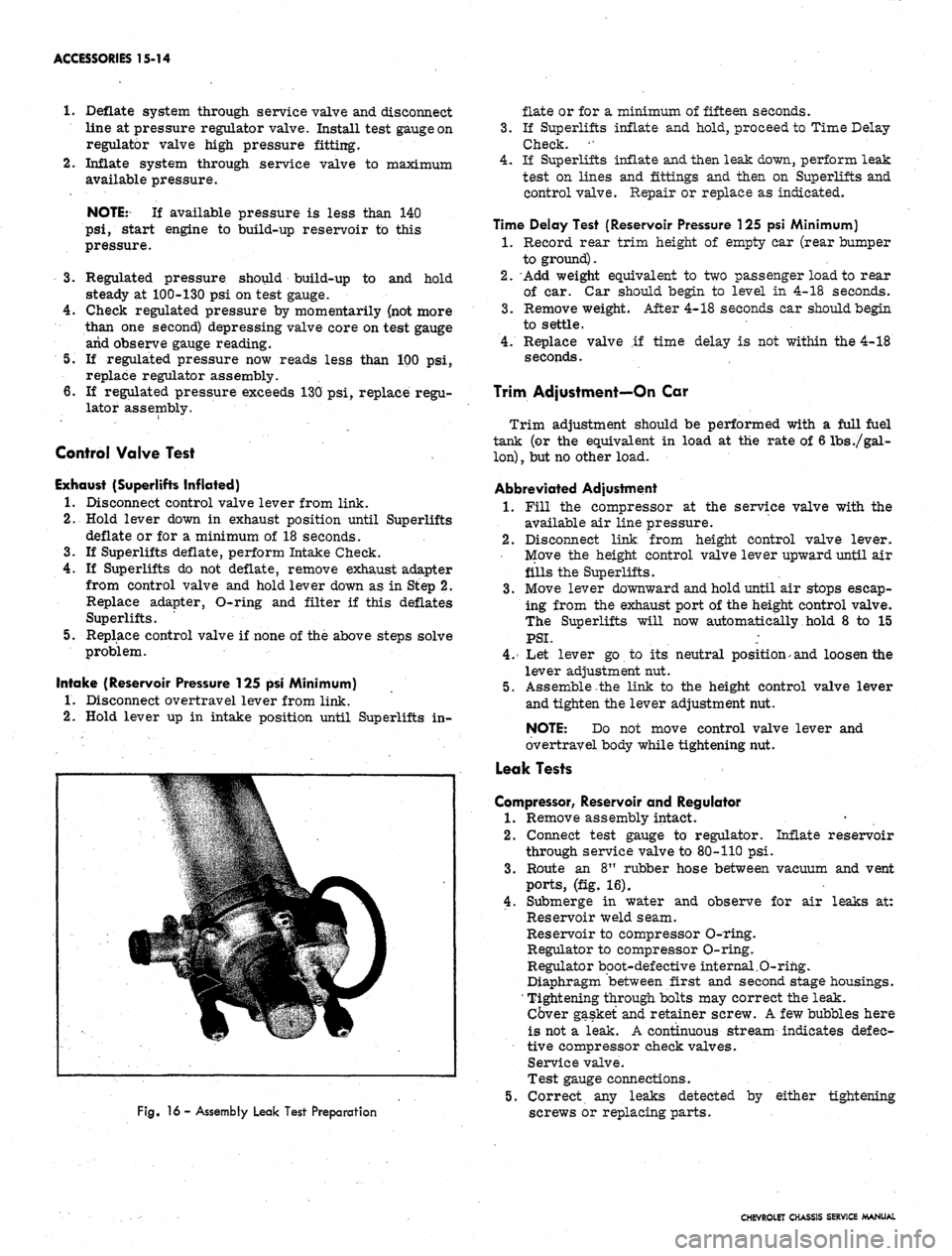
Fig.
16 - Assembly Leak Test Preparation
flate or for a minimum of fifteen seconds.
3.
If Superlifts inflate and hold, proceed to Time Delay
Check. '•
4.
If Superlifts inflate and then leak down, perform leak
test on lines and fittings and then on Superlifts and
control valve. Repair or replace as indicated.
Time Delay Test (Reservoir Pressure 125 psi Minimum)
1.
Record rear trim height of empty car (rear bumper
to ground).
2.
Add weight equivalent to two passenger load to rear
of car. Car should begin to level in 4-18 seconds.
3.
Remove weight. After 4-18 seconds car should begin
to settle.
4.
Replace valve if time delay is not within the 4-18
seconds.
Trim Adjustment—On Car
Trim adjustment should be performed with a full fuel
tank (or the equivalent in load at the rate of 6 lbs
./gal-
lon)
,
but no other load.
Abbreviated Adjustment
1.
Fill the compressor at the service valve with the
available air line pressure.
2.
Disconnect link from height control valve lever.
Move the height control valve lever upward until air
fills the Superlifts.
3.
Move lever downward and hold until air stops escap-
ing from the exhaust port of the height control valve.
The Superlifts will now automatically hold 8 to 15
PSI.
;
4.
Let lever go to its neutral position> and loosen the
lever adjustment nut.
5.
Assemble the link to the height control valve lever
and tighten the lever adjustment nut.
NOTE: Do not move control valve lever and
overtravel body while tightening nut.
Leak Tests
Compressor, Reservoir and Regulator
1.
Remove assembly intact.
2.
Connect test gauge to regulator. Inflate reservoir
through service valve to 80-110 psi.
3.
Route an 8" rubber hose between vacuum and vent
ports,
(fig. 16).
4.
Submerge in water and observe for air leaks at:
Reservoir weld seam.
Reservoir to compressor O-ring.
Regulator to compressor O-ring.
Regulator boot-defective internal.O-rihg.
Diaphragm between first and second stage housings.
' Tightening through bolts may correct the leak.
Cover gasket and retainer screw. A few bubbles here
is not a leak. A continuous stream indicates defec-
tive compressor check valves.
Service valve.
Test gauge connections.
5.
Correct any leaks detected by either tightening
screws or replacing parts.
CHEVROLET CHASSIS SERVICE MANUAL
Page 639 of 659

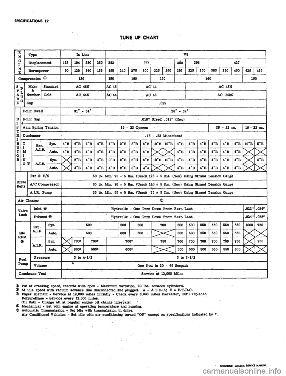
SPECIFICATIONS
12
TUNE UP CHART
E
N
G
I
N
E
Type
Displacement
Horsepower
Compression ®
srp
;•
D
S
R
I
B
TT
T
o
R
Make
0.
Number
Standard
Cold
Gap
Point Dwell
Point Gap
1 ,
Arm Spring Tension
Condenser
T
I
M
j
N
G ®
Drive
Belts
Exc.
A.I.R.
AXR.
Syn.
Auto.
Syn;
Auto.
Fan & P/S
A/C Compressor
A.LR. Pump
Air Cleaner
Valve
Lash
Idle
<§>
Fuel.
Pump
Inlet
Exhaust
<§)
Exc.
A.LR.
A.LR.
Syn.
Auto.
Syn.
Auto.
Pressure
Volume
Crankcase Vent
In Line
153
90
194
120
230
140
250
155
130
AC
AC
31° -
46N
44N
• 34°
V8
283
195
150
AC 45
AC 44
327
210
275
300
160
325
350
150
350
295
396
325
350
427
385
390
400
160
AC 44
AC 43
425
435
150
AC 43N
AC C42N
.035
28° - 32°
.4)16"
(Used) .019" (New)
<
19 - 23 Ounces
4°B
4°B
4°B
4°B
2°B
4°B
4°B
4°B
4°B
4°B
28
- 32 (
yz.
19 - 23 oz.
.18 - .23 Microfarad
4°B
4°B
4°B
4ftB
4°B
4°B
0°B
4°B
50 lb. Min. 75
65 Jh. Min. 95
35 lb..Min. 5£
500
2°B
2°B
2°B
2°B
8PB
8°B
6°B'
6°B
6°B
6°B
6°B
4°A
10°B
X
ib°B
X
10PB
X
10°B
X
4°B
4°B
4°B
4°B
4°B
4°B
4°B
4°B
4°B
4°B
4°B
4°B
± 5 lbs.
(Used):
125 ± 5 lbs. (New) Using Strand '
± 5 lbs.. (Used) 140 ± 5 lbs. (New) Using Strand '
>
± 5 lbs. (Used) 75 ± 5 lbs. (New) Using Strand r
Hydraulic - One Turn Down From Zero Lash
Hydraulic - One Turn Down From Zero Lash
500
X
700*
600*
3 to
700*
500*
4-1/2
500
600
500
500
700*
600*
700
750
500
500
700
500
500
500
700
500
550
550
700
500
4°B
4°B
4°B
4°B
4°B
4°B
4°B
4°B
4°B
4°B
4°B
4°B
Tension Gauge
Tension Gauge
Tension Gauge
550
550
700
550
550
550
700
550
550
550
750
600
10°B
5°B
X
X
.022"
.024"
1000
X
X
X
.024"
.028"
750
X
750
X
5 to 6-1/2
One Pint in 30 - 45 Seconds
Service at 12,000 Miles
OD Psi at cranking speed, throttle wide open - Maximum variation, 20 lbs. between cylinders.
© At idle speed with vacuum advance line disconnected and plugged. A = A.T.D.C.; B = B.T.D.C.
® Paper Element - Service at 12,000 miles initially - Check every 6,000 miles thereafter, until replaced.
Polyurethane - Service every 12,000 miles.
Oil Bath - Change oil at regular engine oil change intervals.
® Mechanical - Set with engine at operating temperature and running.
@ Automatic Transmission - Set idle with transmission in drive.
Air Conditioned Vehicles - Set idle with air conditioning turned "ON" except on specifications indicated by *.
CHEVROLET CHASSIS SERVICE MANUAL