differential CHEVROLET CAMARO 1967 1.G Chassis User Guide
[x] Cancel search | Manufacturer: CHEVROLET, Model Year: 1967, Model line: CAMARO, Model: CHEVROLET CAMARO 1967 1.GPages: 659, PDF Size: 114.24 MB
Page 219 of 659
REAR SUSPENSION AND DRIVE LINE 4-29
REAR AXLE NOISE DIAGNOSIS
Mechanical failures of the rear axle are relatively
simple to locate and correct. Noise in a rear axle is a
little more difficult to diagnose and repair. One of the
most essential parts of rear axle service is proper
diagnosis.
Ail rear axles are noisy to a certain degree. The
action of transmitting the high engine torque through a
90° turn reducing propeller shaft speed produces noise
in rear axles. This point establishes the need for a line
between normal and abnormal or unacceptable axle
noises.
Slight axle noise heard only at a certain speed or under
remote conditions must be considered normal. Axle noise
tends to "peak" at varying speeds and the noise is in no
way indicative of trouble in the axle.
If noise is present in an objectionable form, loud or at
all speeds, an effort should be made to isolate the noise
as being in one particular unit of the vehicle. Axle noise
is often confused with other noises such as tire noise,
transmission noise, propeller shaft vibration and uni-
versal joint noise. Isolation of the noise as in any one
unit requires skill and experience. An attempt to elimini-
ate a slight noise may baffle even the best of diagnos-
ticians. Such practices as raising tire pressure to
eliminate tire noise, listening for the noise at varying
speeds and on drive, float and coast, and under proper
highway conditions, turning the steering wheel from left
to right to detect wheel bearing noise, will aid even the
beginner in detecting alleged axle noises. Axle noises
fall into two categories: gear noise and bearing noise.
GEAR NOISE
Abnormal gear noise can be recognized since it pro-
duces a cycling pitch and will be very pronounced in the
speed range at which it occurs, appearing under either
"drive," "float" or "coast" conditions. Gear noise
tends to peak in a narrow speed range or ranges, while
bearing noise will tend to remain constant in pitch. Ab-
normal gear noise is rare and usually originates from
the scoring of the ring gear and pinion teeth as a result
of insufficient or improper lubrication in new assemblies.
Side gears seldom give trouble as they are used only
when the rear wheels travel at different speeds.
BEARING NOISE
Defective bearings will always produce a whine that is
constant in pitch and varies with vehicle speed. This fact
will allow you to distinguish between bearing noise and
gear noise.
1.
Pinion bearing noise resulting from a bearing failure
can be identified by a constant rough sound. Pinion
bearings are rotating at a higher speed than differen-
tial side bearings or axle shaft bearings. This
particular noise can be picked up best by testing the
car on a smooth road (black top). However, care
should be taken not to confuse tire noise with bear-
ing or gear noise. If any doubt exists, tire treads
should be examined for irregularities that would
produce such noise.
2.
Wheel bearing noise may be confused with rear axle
noise. To differentiate between wheel bearings and
rear axle, drive the vehicle on a smooth road at
medium-low speed. With traffic permitting, turn
Fig.
74—Scored Hypoid Ring Gear
the vehicle sharply right and left. If noise is caused
by wheel bearings, it will increase in the turns be-
cause of the side loading. If noise cannot be isolated
to front or rear wheel bearings, inspection will be
necessary.
3.
Side bearings will produce a constant rough noise of
a slower nature than pinion bearings. Side bearing
noise will not fluctuate in the above wheel bearing
test.
Failure Analysis
The most common types of rear axle failures are
hypoid gear tooth scoring and fracture, differential gear
fracture. and/or differential bearing failure, and axle
shaft bearing failure.
Fig.
75-Cracked Hypoid Ring Gear
CHEVROLET CHASSIS SERVICE MANUAL
Page 220 of 659
REAR SUSPENSION AND DRIVE LINE 4-30
Fig.
76—Differential Gear Failure
Hypoid Gears
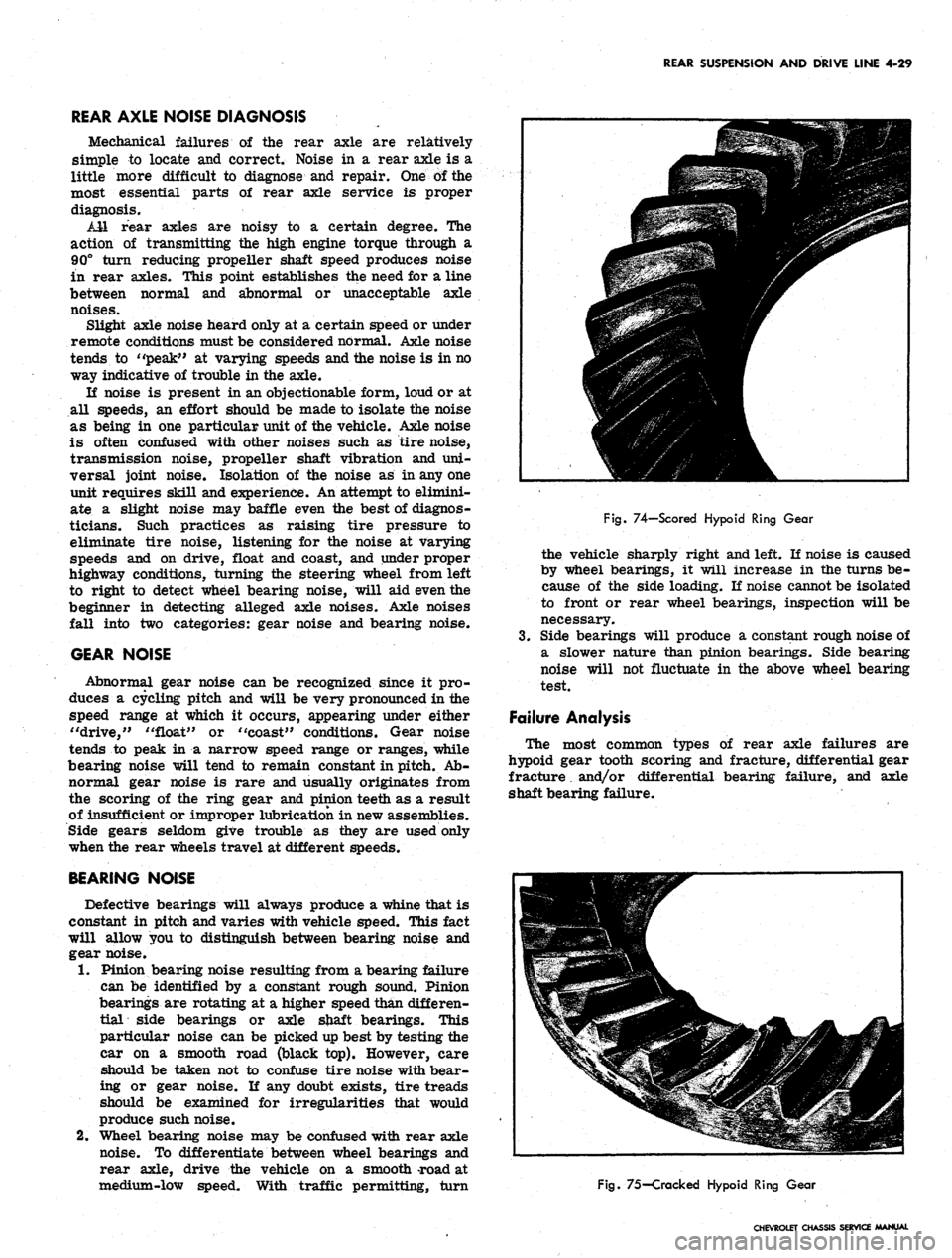
Hypoid gear tooth scoring (fig. 74) is caused generally
by improper break-in, incorrect lube, insufficient gear
backlash or improper 'ring/pinion gear alignment. The
scoring will progressively lead to complete erosion of
the gear tooth, or gear tooth pitting and eventual fracture
with possible attendant damage to bearings, if the initial
scoring condition is not diagnosed in time and corrected.
Hypoid gear scoring is easily recognized by its char-
acteristic loud whine in either drive, coast or under both
conditions. Another cause of hypoid tooth fracture (fig.
75) is extended overloading of the gear set which will
produce fatigue fracture, or shock loading which will
result in sudden failure.
Differential Gears
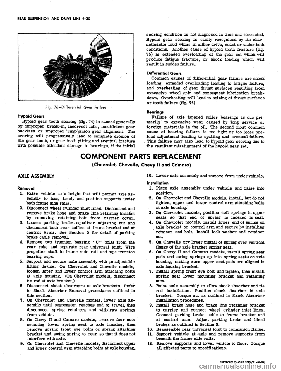
Common causes of differential gear failure are shock
loading, extended overloading leading to fatigue failure,
and overheating of gear thrust surfaces resulting from
excessive wheel spin and consequent lubrication break-
down. Overheating will lead to seizing of thrust surfaces
or tooth failure (fig. 76).
Bearings
• Failure of axle tapered roller bearings is due pri-
marily to excessive wear caused by long service or
foreign materials in the oil. The second most common
cause of bearing failure is too tight or too loose pre-
load adjustment leading to spalling and eventual failure.
This failure may also lead to hypoid gear scoring due to
the resultant misalignment of the hypoid gear set.
COMPONENT PARTS REPLACEMENT
(Chevrolet, Cheveile, Chevy II and Camaro)
AXLE ASSEMBLY
Removal
1.
Raise vehicle to a height that will permit axle as-
sembly to hang freely and position supports under
both frame side rails.
2.
Disconnect wheel cylinder inlet lines. Disconnect and
remove brake hose and brake line retaining bracket
by removing retaining bolt from carrier cover.
3.
Loosen parking brake equalizer adjusting nut and
disconnect both rear cables at frame bracket and at
control arms. See Section 5 for detail of parking
brake cable removal.
4.
Remove two trunnion bearing "U" bolts from the
rear yoke and separate rear universal joint. Wire
propeller shaft to frame side rail and tape trunnion
bearing cups.
5. Support arid secure axle assembly with an adjustable
lifting device. On Chevrolet and Cheveile models,
loosen upper and lower control arm attaching bolts
at axle housing. (On Chevrolet models, disconnect
tie rod at axle bracket.)
6. Disconnect shock absorbers at axle brackets. Refer
to Shock Absorber Removal procedures outlined in
this section.
7. On Chevrolet and Cheveile models, lower axle as-
sembly until suspension reaches end of travel, then
disconnect spring retainers and withdraw springs
from vehicle.
8. On Chevy II and Camaro models, remove four nuts
securing lower spring seat to axle housing, then
remove spring front eye bolts or spring attaching
bracket and swing spring to rear so that it does not
interfere with axle.
9. On Chevrolet and Cheveile models, disconnect upper
and lower control arm attaching bolts at axle housing*
10.
Lower axle assembly and remove from under vehicle.
Installation
1.
Place axle assembly under vehicle and raise into
position.
2.
On Chevrolet and Cheveile models, install, but do not
tighten, upper and lower control arm attaching bolts
at axle housing.
3.
On Chevrolet models, position coil springs in upper
seats so that end of spring is indexed in seat.
4.
On Chevrolet models, install lower end of spring on
axle bracket or control arm and secure by installing
retainer and bolt. Install lock washer and retainer
nut.
5. On Cheveile pry lower pigtail of spring over vertical
flange of the axle bracket spring seat.
6. On Chevy II and Camaro models, install spring seat
pads and swing springs up into spring seats on axle
housing, making sure upper seat pads are aligned in
axle housing bracket.
7. Install spring front eye bolt and tighten, then install
spring seat lower mounting bracket and retaining
nuts.
8. Raise axle assembly to allow shock absorber and tie
rod installation. Position shock absorber in axle
bracket. Torque nut as outlined in Shock Absorber
Installation procedures.
9. Install brake hose and brake line retaining bracket
to carrier and connect wheel cylinder inlet lines.
Connect parking brake cable to frame bracket and
at control arm. Adjust parking brake and bleed
brakes as outlined in Section 5.
10.
Reassemble rear universal joint to companion flange.
11.
Support vehicle at axle and remove supports from
beneath the frame side rails.
12.
Remove supports and lower vehicle to floor. Torque
all affected parts to specifications.
CHEVROLET CHASSIS SERVICE MANUAL
Page 221 of 659
REAR SUSPENSION AND DRIVE LINE 4-31
Fig.
77—Differential Pinion Shaft Removal
AXLE SHAFT
Removal
1.
Raise vehicle to desired working height and remove
wheel and tire assembly and brake drum.
2.
Clean all dirt from area of carrier cover. *
3.
Drain lubricant from carrier by removing cover.
4.
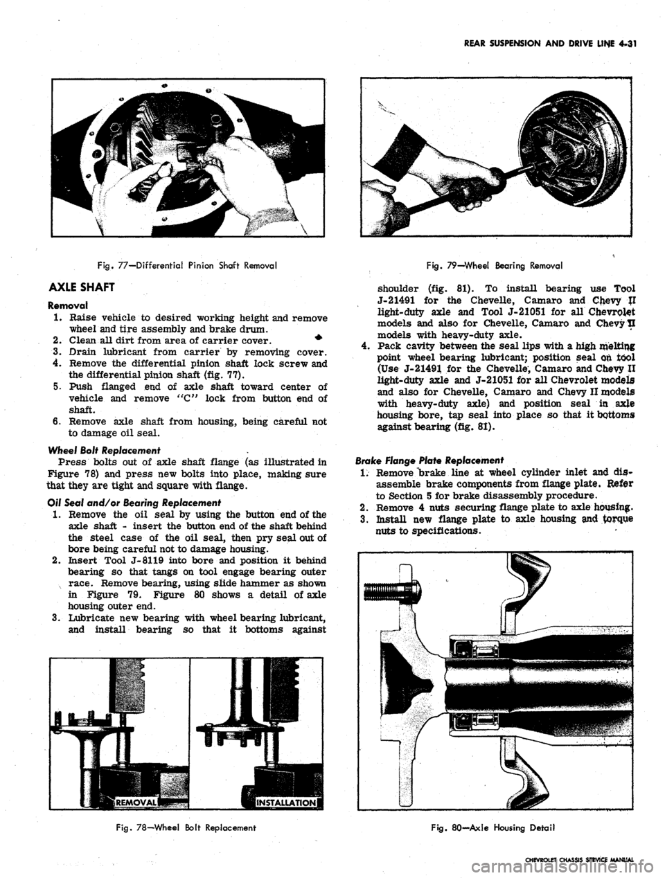
Remove the differential pinion shaft lock screw and
the differential pinion shaft (fig. 77).
5. Push flanged end of axle shaft toward center of
vehicle and remove "C" lock from button end of
shaft.
6. Remove axle shaft from housing, being careful not
to damage oil seal.
Wheel Bolt Replacement .
Press bolts out of axle shaft flange (as illustrated in
Figure 78) and press new bolts into place, making sure
that they are tight and square with flange.
Off Seal and/or Bearing Replacement
•1.
Remove the oil seal by using the button end of the
axle shaft - insert the button end of the shaft behind
the steel case of the oil seal, then pry seal out of
bore being careful not to damage housing.
2.
Insert Tool J-8119 into bore and position it behind
bearing so that tangs on tool engage bearing outer
x race. Remove bearing, using slide hammer as shown
in Figure 79. Figure 80 shows a detail of axle
housing outer end.
3.
Lubricate new bearing with wheel bearing lubricant,
and install bearing so that it bottoms against
Fig.
79—Wheel Bearing Removal
shoulder (fig. 81). To install bearing use Tool
J-21491 for the Chevelle, Camaro and Chevy JI
light-duty axle and Tool J-21051 for all Chevrolet
models and also for Chevelle, Camaro and Chevy tl
models with heavy-duty axle.
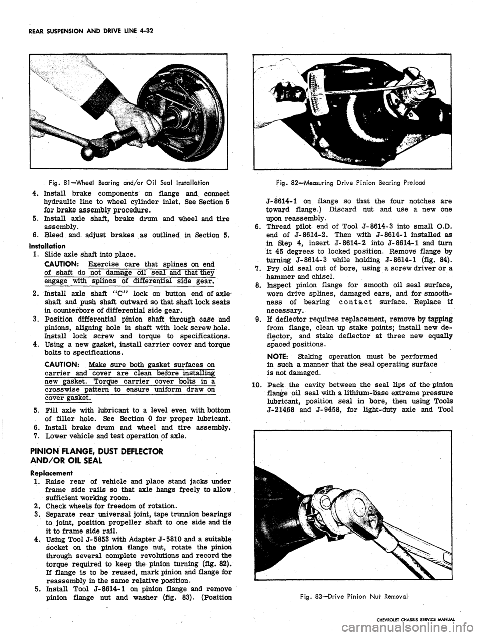
Pack cavity between the seal lips with a high melting
point wheel bearing lubricant; position seal on tool
(Use J-21491 for the Chevelle, Camaro and Chevy II
light-duty axle and J-21051 for all Chevrolet models
and also for Chevelle, Camaro and Chevy II models
with heavy-duty axle) and position seal in axle
housing bore, tap seal into place so that it bottoms
against bearing (fig. 81).
Brake Flange Plate Replacement
1.
Remove "brake line at wheel cylinder inlet and dis-
assemble brake components from flange plate. Refer
to Section 5 for brake disassembly procedure.
2.
Remove 4 nuts securing flange plate to axle housing.
3.
Install new flange plate to axle housing and torque
nuts to specifications.
Fig.
78—Wheel Bolt Replacement
Fig.
80-Axle Housing Detail
CHEVROLET CHASSIS SERVICE MANUAL
Page 222 of 659
REAR SUSPENSION AND DRIVE LINE 4-32
HP?
Fig.
81
—Whed Bearing and/or Oil Seal Installation
4.
Install brake components on flange and connect
hydraulic line to wheel cylinder inlet. See Section 5
for brake assembly procedure.
5. Install axle shaft, brake drum and wheel and tire
assembly.
6. Bleed and. adjust brakes as outlined in Section 5.
Installation
1.
Slide axle shaft into place.
CAUTION: Exercise care that splines on end
of shaft do not damage oil seal and that they
engage with splines of differential side gear/
2.
Install axle shaft "C" lock on button end of axle-
shaft and push shaft outward so that shaft lock seats
in counterbore of differential side gear.
3.
Position differential pinion shaft through case and
pinions, aligning hole in shaft with lock screw hole.
Install lock screw and torque to specifications.
4.
Using a new gasket, install carrier cover and torque
bolts to specifications.
CAUTION: Make sure both gasket surfaces on
carrier and cover are clean before installing
new gasket. Torque carrier cover bolts in a
crosswise pattern to ensure uniform draw on
cover gasket.
5. Fill axle with lubricant to a level even with bottom
of filler hole. See Section 0 for proper lubricant.
6. Install brake drum and wheel and tire assembly.
7. Lower vehicle and test operation of axle.
PINION FLANGE, DUST DEFLECTOR
AND/OR OIL SEAL
Replacement
1.
Raise rear of vehicle and place stand jacks under
frame side rails so that axle hangs freely to allow
sufficient working room.
2.
Check wheels for freedom of rotation.
3.
Separate rear universal joint, tape trunnion bearings
to joint, position propeller shaft to one side and tie
it to frame side rail.
4.
Using Tool J-5853 with Adapter J-5810 and a suitable
socket on the pinion flange nut, rotate the pinion
through several complete revolutions and record the
torque required to keep the pinion turning (fig. 82).
If flange is to be reused, mark pinion and flange for
reassembly in the same relative position.
5. Install Tool J-8614-1 on pinion flange and remove
pinion flange nut and washer (fig. 83). (Position
Fig. 82—Measuring Drive Pinion Bearing Preload
J-8614-1 on flange so that the four notches are
toward flange.) Discard nut and use a new one
upon reassembly.
6. Thread pilot end of Tool J-8614-3 into small O.D.
end of J-8614-2. Then with J-8614-1 installed as
in Step 4, insert J-8614-2 into J-8614-1 and turn
it 45 degrees to locked position. Remove flange by
turning J-8614-3 while holding J-8614-1 (fig. 84).
7. Pry old seal out of bore, using a screw driver or a
hammer and chisel.
8. Inspect pinion flange for smooth oil seal surface,
worn drive splines, damaged ears, and for smooth-
ness of bearing contact surface. Replace if
necessary.
9. If deflector requires replacement, remove by tapping
from flange, clean up stake points; install new de-
flector, and stake deflector at three new equally
spaced positions.
NOTE:
Staking operation must be performed
in such a manner that the seal operating surface
is not damaged.
1.0. Pack the cavity between the seal lips of the pinion
flange oil seal with a lithium-base extreme pressure
lubricant, position seal in bore, then using Tools
J-21468 and J-9458, for light-duty axle and Tool
Fig. 83-—Drive Pinion Nut Removal
CHEVROLET CHASSIS SERVICE MANUAL
Page 226 of 659
REAR SUSPENSION AND DRIVE LINE 4-36
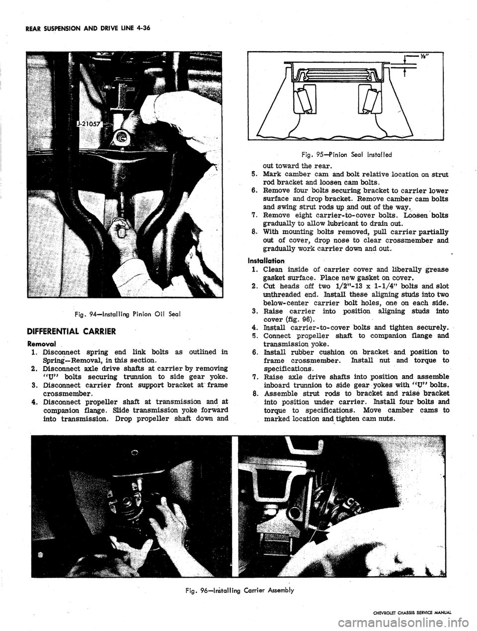
Fig.
94—Installing Pinion Oil Seal
DIFFERENTIAL CARRIER
Removal
1.
Disconnect spring end link bolts as outlined in
Spring—Removal, in this section.
2.
Disconnect axle drive shafts at carrier by removing
"U"
bolts securing trunnion to side gear yoke.
3.
Disconnect carrier front support bracket at frame
crossmember.
4.
Disconnect propeller shaft at transmission and at
companion flange. Slide transmission yoke forward
into transmission. Drop propeller shaft down and
Fig.
95-Pinion Sea! Installed
out toward the rear.
5. Mark camber cam and bolt relative location on strut
rod bracket and loosen cam bolts.
6. Remove four bolts securing bracket to carrier lower
surface and drop bracket. Remove camber cam bolts
and swing strut rods up and out of the way.
7. Remove eight carrier-to-cover bolts. Loosen bolts
gradually to allow lubricant to drain out.
8. With mounting bolts removed, pull carrier partially
out of cover, drop nose to clear crossmember and
gradually work carrier down and out.
Installation
1.
Clean inside of carrier cover and liberally grease
gasket surface. Place new gasket on cover.
2.
Cut heads off two l/2"-13 x 1-1/4" bolts and slot
unthreaded end. Install these aligning studs into two
below-center carrier bolt holes, one on each side.
3.
Raise carrier into position aligning studs into
cover (fig. 96).
4.
Install carrier-to-cover bolts and tighten securely.
5. Connect propeller shaft to companion flange and
transmission yoke.
6. Install rubber cushion on bracket and position to
frame crossmember. Install hut and torque to
specifications.
7. Raise axle drive shafts into position and assemble
inboard trunnion to side gear yokes with "U" bolts.
8. Assemble strut rods to bracket and raise bracket
into position under carrier. Install four bolts and
torque to specifications. Move camber cams to
marked location and tighten cam nuts.
Fig.
96—Installing Carrier Assembly
CHEVROLET CHASSIS SERVICE MANUAL
Page 227 of 659
REAR SUSPENSION AND DRIVE LINE 4-37
9. Connect spring end link bolts as outlined under
Spring--Installation, in this section.
10.
Remove filler plug, located on right side of cover,
and fill -with hypoid lubricant to level of filler hole.
11.
Lower vehicle and road test for leaks, noise and
general performance.
POSITRACTION DIFFERENTIAL UNIT
The optionally available Positraction differential unit
is installed in the conventional carrier to replace the
standard differential unit.
Service procedures for the Positraction equipped axle
are the same as on a conventional axle except for the.
operations listed below.
On the Vehicle Check
If vehicle is equipped with a manual transmission, shift
transmission into neutral.
1.
Raise rear of vehicle until wheels are off the ground,
remove one wheel and tire assembly.
2.
Attach Adapter J-5748 to axle shaft flange and install
a
1/2-13
bolt into adapter (fig. 97).
3.
With wheel and tire assembly still on vehicle held
firmly to prevent turning, measure torque required
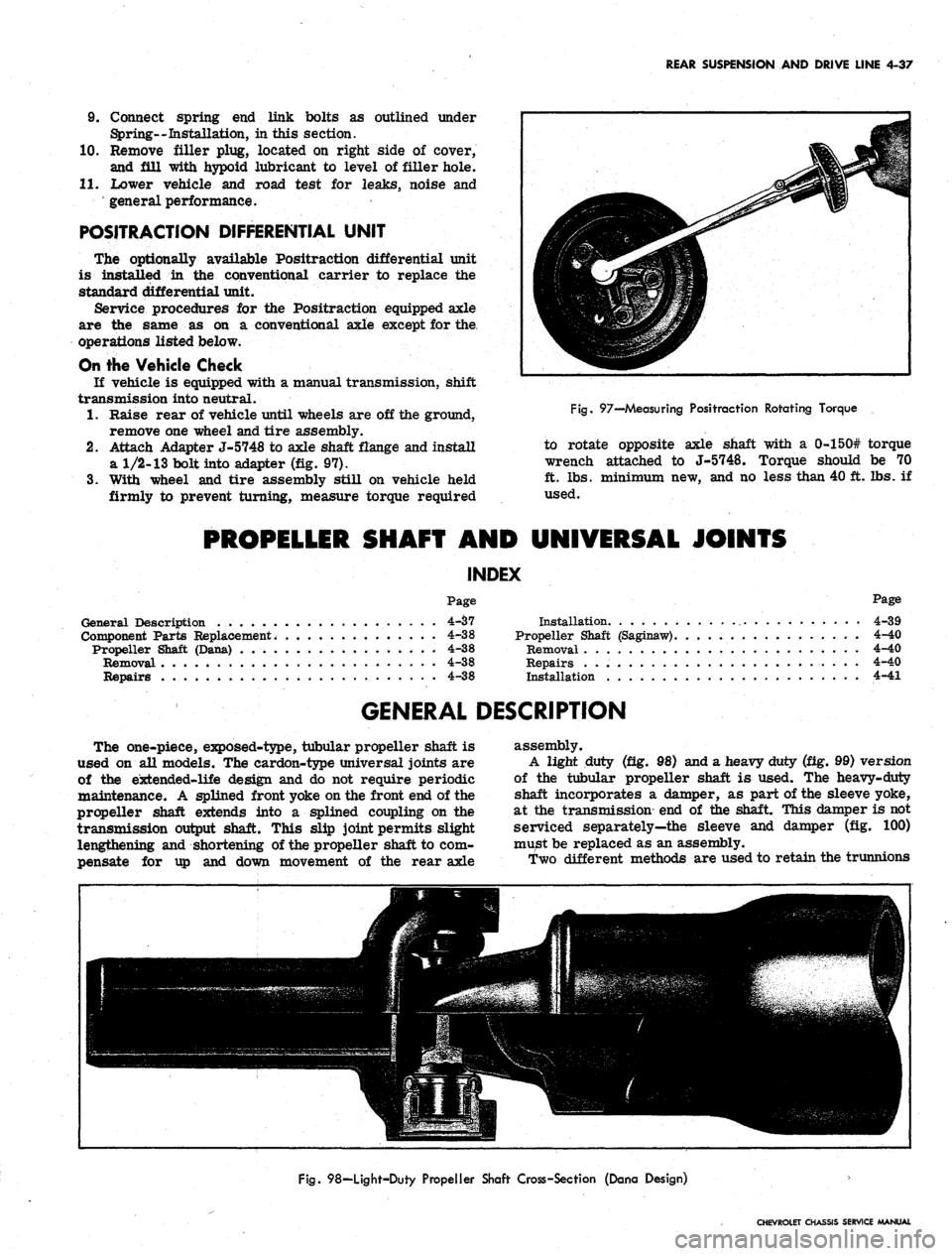
Fig.
97—Measuring Positraction Rotating Torque
to rotate opposite axle shaft with a 0-150# torque
wrench attached to J-5748. Torque should be 70
ft.
lbs. minimum new, and no less than 40 ft. lbs. if
used.
PROPELLER SHAFT AND UNIVERSAL JOINTS
INDEX
Page
Page
General Description 4-37
Component Parts Replacement. 4-38
Propeller Shaft (Dana) 4-38
Removal 4-38
Repairs 4-38
Installation 4-39
Propeller Shaft (Saginaw) 4-40
Removal 4-40
Repairs 4-40
Installation 4-41
GENERAL DESCRIPTION
The one-piece, exposed-type, tubular propeller shaft is
used on all models. The cardon-type universal joints are
of the extended-life design and do not require periodic
maintenance. A splined front yoke on the front end of the
propeller shaft extends into a splined coupling on the
transmission output shaft. This slip joint permits slight
lengthening and shortening of the propeller shaft to com-
pensate for up and down movement of the rear axle
assembly.
A light duty (fig. 98) and a heavy duty (fig. 99) version
of the tubular propeller shaft is used. The heavy-duty
shaft incorporates a damper, as part of the sleeve yoke,
at the transmission end of the shaft. This damper is not
serviced separately—the sleeve and damper (fig. 100)
must be replaced as an assembly.
Two different methods are used to retain the trunnions
Fig.
98—Light-Duty Propeller Shaft Cross-Section (Dana Design)
CHEVROLET CHASSIS SERVICE MANUAL
Page 230 of 659
REAR SUSPENSION AND DRIVE LINE 4-40
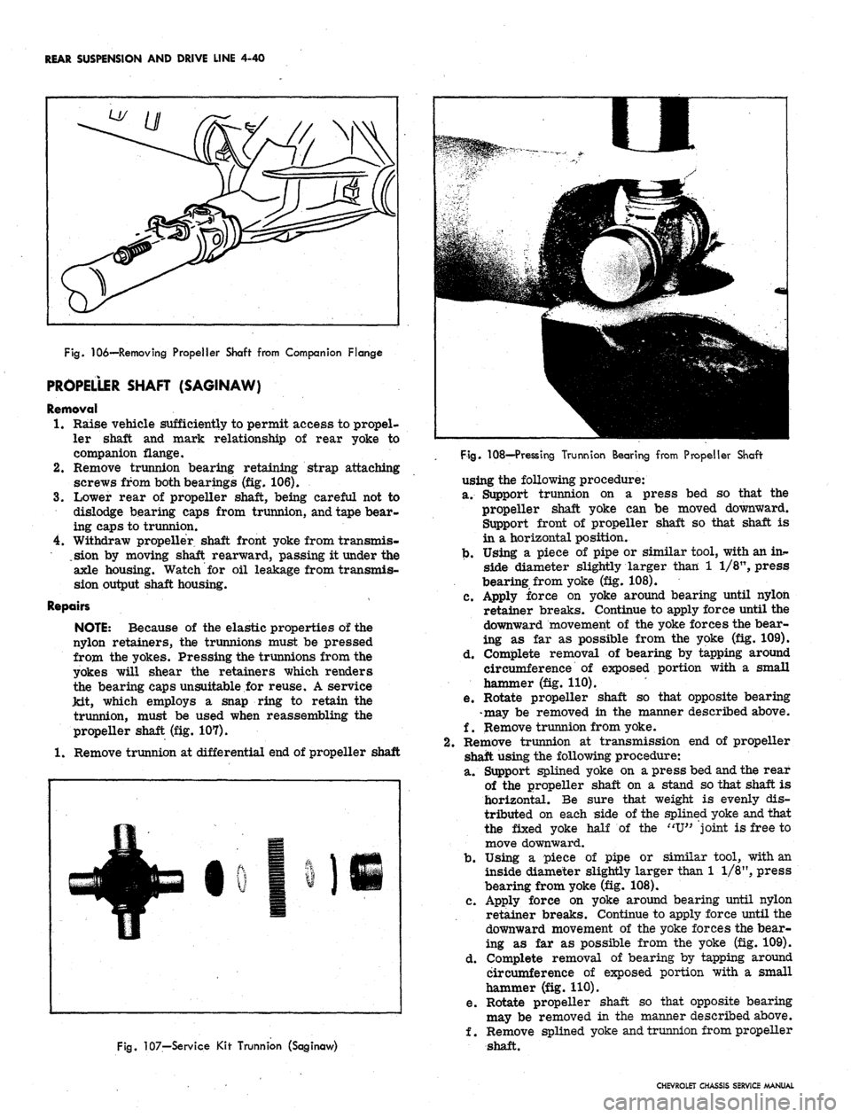
Fig.
106—Removing Propeller Shaft from Companion Flange
PROPELLER SHAFT (SAGINAW)
Removal
1.
Raise vehicle sufficiently to permit access to propel-
ler shaft and mark relationship of rear yoke to
companion flange.
2.
Remove trunnion bearing retaining strap attaching
screws from both bearings (fig. 106).
3.
Lower rear of propeller shaft, being careful not to
dislodge bearing caps from trunnion, and tape bear-
ing caps to trunnion.
4.
Withdraw propeller shaft front yoke from transmis-
.sion by moving shaft rearward, passing it under the
axle housing. Watch for oil leakage from transmis-
sion output shaft housing.
Repairs
NOTE:
Because of the elastic properties of the
nylon retainers, the trunnions must be pressed
from the yokes. Pressing the trunnions from the
yokes will shear the retainers which renders
the bearing caps unsuitable for reuse. A service
Jdt, which employs a snap ring to retain the
trunnion, must be used when reassembling the
propeller shaft (fig. 107).
1.
Remove trunnion at differential end of propeller shaft
Fig.
107—Service Kir Trunnion (Saginaw)
Fig.
108—Pressing Trunnion Bearing from Propeller Shaft
using the following procedure:
a. Support trunnion on a press bed so that the
propeller shaft yoke can be moved downward.
Support front of propeller shaft so that shaft is
in a horizontal position.
b.
Using a piece of pipe or similar tool, with an ins-
side diameter slightly larger than 1 1/8", press
bearing from yoke (fig. 108).
c. Apply force on yoke around bearing until nylon
retainer breaks. Continue to apply force until the
downward movement of the yoke forces the bear-
ing as far as possible from the yoke (fig. 109).
d. Complete removal of bearing by tapping around
circumference of exposed portion with a small
hammer (fig. 110).
e. Rotate propeller shaft so that opposite bearing
-may be removed in the manner described above.
f. Remove trunnion from yoke.
Remove trunnion at transmission end of propeller
shaft using the following procedure:
a. Support splined yoke on a press bed and the rear
of the propeller shaft on a stand so that shaft is
horizontal. Be sure that weight is evenly dis-
tributed on each side of the splined yoke and that
the fixed yoke half of the "U" joint is free to
move downward.
b.
Using a piece of pipe or similar tool, with an
inside diameter slightly larger than 1 1/8", press
bearing from yoke (fig. 108).
c. Apply force on yoke around bearing until nylon
retainer breaks. Continue to apply force until the
downward movement of the yoke forces the bear-
ing as far as possible from the yoke (fig. 109).
d. Complete removal of bearing by tapping around
circumference of exposed portion with a small
hammer (fig. 110).
e. Rotate propeller shaft so that opposite bearing
may be removed in the manner described above.
f. Remove splined yoke and trunnion from propeller
shaft.
CHEVROLET CHASSIS SERVICE MANUAL
Page 231 of 659
REAR SUSPENSION AND DRIVE LINE 4-41
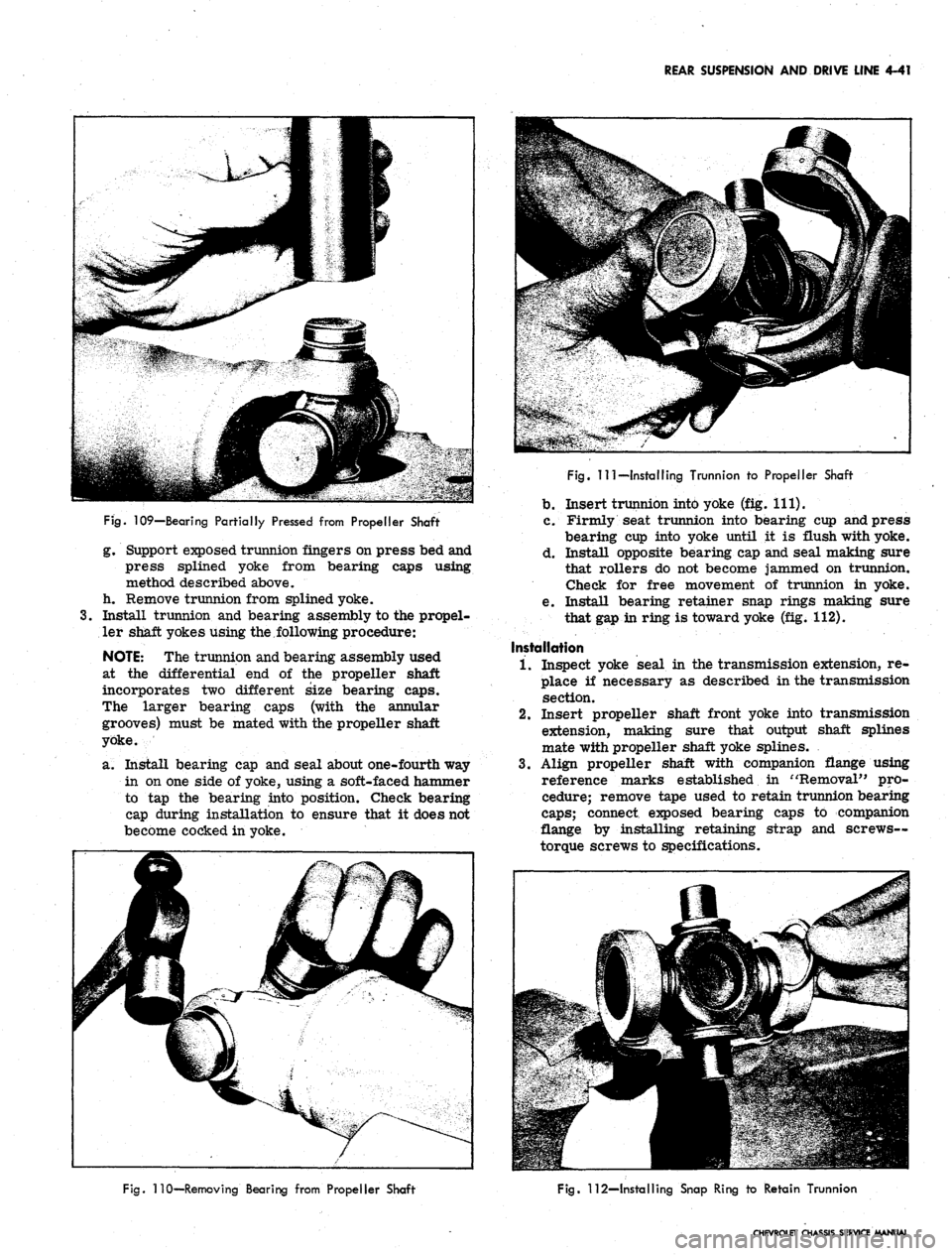
Fig.
109—Bearing Partially Pressed from Propeller Shaft
g. Support exposed trunnion fingers on press bed and
press splined yoke from bearing caps using
method described above,
h. Remove trunnion from splined yoke.
3.
Install trunnion and bearing assembly to the propel-
ler shaft yokes using the,following procedure:
NOTE:
The trunnion and bearing assembly used
at the differential end of the propeller shaft
incorporates two different size bearing caps.
The larger bearing caps (with the annular
grooves) must be mated with the propeller shaft
yoke.
a. Install bearing cap and seal about one-fourth way
in on one side of yoke, using a soft-faced hammer
to tap the bearing into position. Check bearing
cap during installation to ensure that it does not
become cocked in yoke.
Fig.
Ill—Installing Trunnion to Propeller Shaft
b.
Insert trunnion into yoke (fig. 111).
c. Firmly seat trunnion into bearing cup and press
bearing cup into yoke until it is flush with yoke.
d. Install opposite bearing cap and seal making sure
that rollers do not become jammed on trunnion.
Check for free movement of trunnion in yoke.
e. Install bearing retainer snap rings making sure
that gap in ring is toward yoke (fig. 112).
Installation
1.
Inspect yoke seal in the transmission extension, re-
place if necessary as described in the transmission
section.
2.
Insert propeller shaft front yoke into transmission
extension, making sure that output shaft splines
mate with propeller shaft yoke splines.
3.
Align propeller shaft with companion flange using
reference marks established in "Removal" pro-
cedure; remove tape used to retain trunnion bearing
caps;
connect exposed bearing caps to companion
flange by installing retaining strap and screws—
torque screws to specifications.
Fig.
110—Removing Bearing from Propeller Shaft
Fig.
112—Installing Snap Ring to Retain Trunnion
CHEVROLET CHASSIS SERVICE MANUAL
Page 368 of 659
CLUTCH AND TRANSMISSIONS 7-9
6. Connect speedometer cable.
7. Install propeller shaft assembly.
8. Fill transmission with lubricant specified in Section
O.
CORVETTE TRANSMISSION REPLACEMENT
, 1. Disconnect battery ground cable.
2.
Pisassemble transmission shift control lever by un-
screwing ball from lever, lifting out
"T"
handle re-
turn spring and "T" handle, then remove the anti-
rattle bushings.
3.
Raise front and rear of vehicle.
4.
Insert a block of wood between the top of the dif-
ferential carrier housing and the underbody (to pre-
vent upward travel of the carrier when the carrier
front support is disconnected).
5. Disconnect the differential carrier front supportfrom
its frame bracket, by removing the nut on the under-
side of the biscuit mount.
6. Pry the carrier downward to relieve load while re-
moving the two center mounting bolts from the car-
rier front support. (To pry carrier downward insert
crowfoot end of a pry bar through the opening in the
carrier front support, hooking end of bar over top of
the center mounting bolt pad cast in the underside of
the carrier.)
7. Pivot carrier support downward for access to prop
shaft "U" joint.
8.
.
Disconnect prop shaft front and then rear "U" bolts.
9. Disconnect parking brake cable from ball socket at
idler lever located near center of underbody.
10.
Remove prop shaft by moving shaft forward.
11.
Remove heat deflectors from the right and left ex-
haust pipe.
12.
Remove left bank exhaust pipe.
13.
Remove right bank exhaust pipe and heat riser.
14.
Disassemble the transmission mount, as follows:
a. Remove the two bolts that attach rear mount
cushion to the rear mount bracket.
b.
Support engine under oil pan and raise engine to
remove load from rear mount cushion.
CAUTION: To avoid damage to oil pan, a suit-
able wide base, heavy wood platform should be
placed between the jack pad and the oil pan.
c. Remove the three transmission mount bracket-
to-
crossm ember bolts and remove mount bracket.
d. Remove the two bolts from mount pad to trans-
mission case and remove rubber mount cushion
and exhaust pipe "yoke".
15.
Disconnect transmission linkage by removing the
shift levers at the transmission side cover.
16.
Disconnect speedo cable at transmission extension.
17.
Remove transmission output shaft slip yoke.
NOTE:
The yoke is removed to avoid tearing
the heat reflecting pad on the underbody, when
the transmission is being removed.
18.
Remove two bolts to disconnect the transmission
gearshift control lever and bracket assembly from
its adapter plate on side of transmission. Lower
transmission assembly from the vehicle, letting the
gearshift lever slide down and through the dust boot
in the console.
19.
Remove transmission-to-clutch housing attaching
bolts.
20.
Slide transmission assembly rearward from clutch
and rotate transmission for access to the three flat
head machine screws in the control lever bracket
adapter plate. Remove adapter plate. Rotate trans-
mission back to the upright position.
21.
To allow room for transmission removal slowly
lower the rear of engine until the tachometer drive
cable at the distributor just clears the horizontal
ledge across the front of dash.
CAUTION: The tachometer cable can be easily
damaged by heavy contact with the dash. Slide
transmission rearward out of the clutch, then
tip front end of transmission downward and
lower the assembly from vehicle.
22.
Reinstall transmission assembly by performing above
steps in reverse order.
TRANSMISSION OVERDRIVE
INDEX
Page
General
Description 7-10
Maintenance
and Adjustments 7—10
Governor
Switch and Pinion .............. 7-10
Sun
Gear Solenoid Oil Seal and Control
Cable
Bracket 7-10
Case
Rear Oil Seal 7-10
Removal
7-10
Installation
. . . . . 7-10
Control
Shaft Lever and Oil Seal 7-10
Speedometer
Driven Gear 7-10
Electrical
Unit Checks 7-11
Overdrive
Relay . 7-11
Page
Air
Gap 7-11
Point
Opening 7-11
Closing
Voltage 7-11
Solenoid
. 7-11
Closing
Coil 7-11
Engaging
Spring . - 7-11
Ignition
Grounding Contact . 7-11
Governor
Switch 7-11
Kickdown
Switch 7-11
Diagnosis
- Overdrive 7-12
Mechanical
. 7-12
Electrical
7-13
CHEVROLET CHASSIS SERVICE MANUAL
Page 370 of 659
CLUTCH AND TRANSMISSIONS 7-11
UPPER ARMATURE STOP
(BEND TO ADJUST POINT OPENING)
Fig.
2B-Adjusting Relay Point Opening
ELECTRICAL UNIT CHECKS
Overdrive Relay
Specifications and checking procedures for this relay
are as follows:
Specifications
Air Gap Oil inch minimum
Point Opening .025 inch
Closing Voltage
8.3-10.2
volts
Armature Sealing Voltage. ..... 11.2 volts maximum
Three checks and adjustments are required on the
overdrive relay; air gap, point opening and closing volt-
age.
The air gap contact point opening checks and adjust-
ments should be made with the battery disconnected.
Air Gap
The air gap should not normally require adjustment
unless the relay has been misadjusted. Check the air gap
with the points barely touching and adjust if necessary by
bending the lower point support (fig, IB).
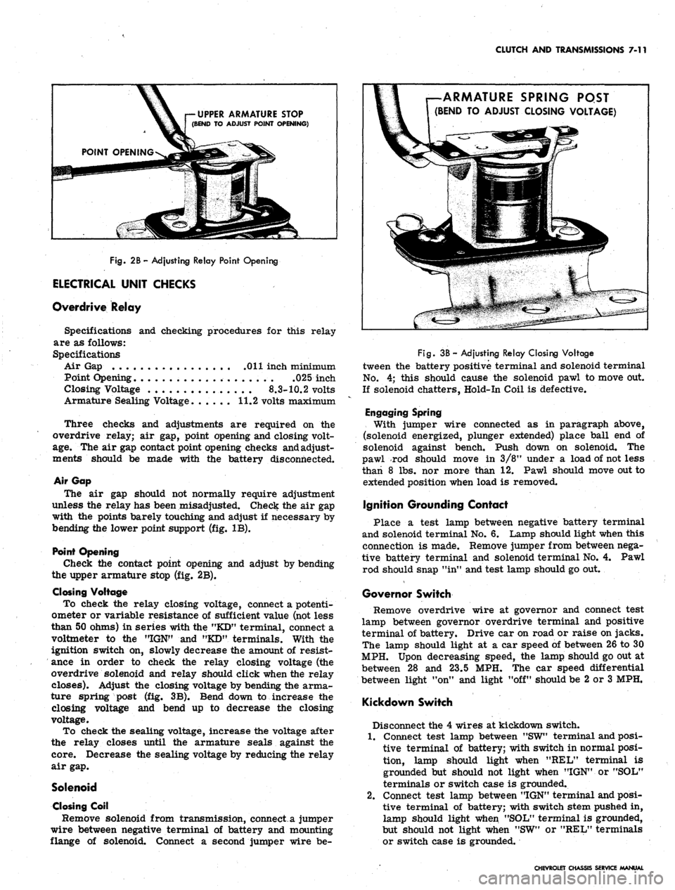
Point Opening
Check the contact point opening and adjust by bending
the upper armature stop (fig. 2B).
Closing Voltage
To check the relay closing voltage, connect a potenti-
ometer or variable resistance of sufficient value (not less
than 50 ohms) in series with the "KD" terminal, connect a
voltmeter to the "IGN" and "KD" terminals. With the
ignition switch on, slowly decrease the amount of resist-
ance in order to check the relay closing voltage (the
overdrive solenoid and relay should click when the relay
closes). Adjust the closing voltage by bending the arma-
ture spring post (fig. 3B). Bend down to increase the
closing voltage and bend up to decrease the closing
voltage.
To check the sealing voltage, increase the voltage after
the relay closes until the armature seals against the
core.
Decrease the sealing voltage by reducing the relay
air gap.
Solenoid
Closing Coil
Remove solenoid from transmission, connect a jumper
wire between negative terminal of battery and mounting
flange of solenoid. Connect a second jumper wire be-
ARMATURE SPRING PQST
(BEND TO ADJUST CLOSING VOLTAGE)
Fig.
3B - Adjusting Relay Closing Voltage
tween the battery positive terminal and solenoid terminal
No.
4; this should cause the solenoid pawl to move out.
If solenoid chatters, Hold-In Coil is defective.
Engaging Spring
With jumper wire connected as in paragraph above,
(solenoid energized, plunger extended) place ball end of
solenoid against bench. Push down on solenoid. The
pawl rod should move in 3/8M under a load of not less
than 8 lbs. nor more than 12. Pawl should move out to
extended position when load is removed.
Ignition Grounding Contact
Place a test lamp between negative battery terminal
and solenoid terminal No. 6. Lamp should light when this
connection is made. Remove jumper from between nega-
tive battery terminal and solenoid terminal No. 4. Pawl
rod should snap "in" and test lamp should go out.
Governor Switch
Remove overdrive wire at governor and connect test
lamp between governor overdrive terminal and positive
terminal of battery. Drive car on road or raise on jacks.
The lamp should light at a car speed of between 26 to 30
MPH. Upon decreasing speed, the lamp should go out at
between 28 and 23.5 MPH. The car speed differential
between light "on" and light "off" should be 2 or 3 MPH.
Kickdown Switch
Disconnect the 4 wires at kickdown switch.
1.
Connect test lamp between "SW" terminal and posi-
tive terminal of battery; with switch in normal posi-
tion, lamp should light when "REL" terminal is
grounded but should not light when "IGN" or "SOL"
terminals or switch case is grounded.
2.
Connect test lamp between "IGN" terminal and posi-
tive terminal of battery; with switch stem pushed in,
lamp should light when "SOL" terminal is grounded,
but should not light when "SW" or "REL" terminals
or switch case is grounded.
CHEVROLET CHASSIS SERVICE MANUAL