parking brake CHEVROLET CAMARO 1967 1.G Chassis User Guide
[x] Cancel search | Manufacturer: CHEVROLET, Model Year: 1967, Model line: CAMARO, Model: CHEVROLET CAMARO 1967 1.GPages: 659, PDF Size: 114.24 MB
Page 199 of 659
REAR SUSPENSION AND DRIVE LINE 4-9
Fig.
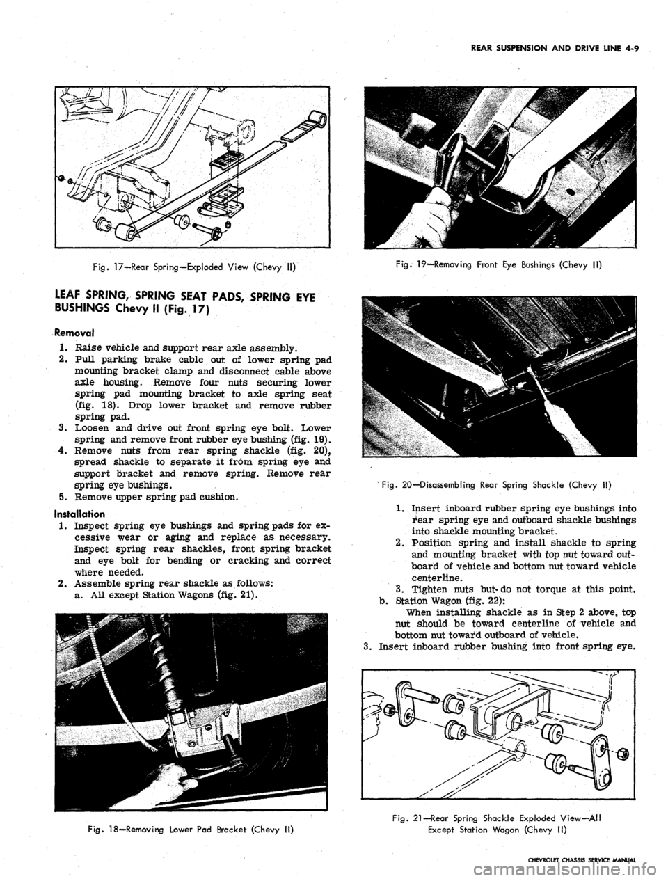
17—Rear Spring—Exploded View (Chevy II)
LEAF SPRING, SPRING SEAT PADS, SPRING EYE
BUSHINGS Chevy II (Fig. 17)
Removal
1.
Raise vehicle and support rear axle assembly.
2.
Pull parking brake cable out of lower spring pad
mounting bracket clamp and disconnect cable above
axle housing. Remove four nuts securing lower
spring pad mounting bracket to axle spring seat
(fig. 18). Drop lower bracket and remove rubber
spring pad.
3.
Loosen and drive out front spring eye bolt. Lower
spring and remove front rubber eye bushing (fig. 19).
4.
Remove nuts from rear spring shackle (fig. 20),
spread shackle to separate it from spring eye and
support bracket and remove spring. Remove rear
spring eye bushings.
5.
Remove upper spring pad cushion.
Installation
1.
Inspect spring eye bushings and spring pads for ex-
cessive wear or aging and replace as necessary.
Inspect spring rear shackles, front spring bracket
and eye bolt for bending or cracking and correct
where needed.
2.
Assemble spring rear shackle as follows:
a. All except Station Wagons (fig. 21).
Fig.
19—Removing Front Eye Bushings (Chevy II)
3.
' Fig. 20—Disassembling Rear Spring Shackle (Chevy II)
1.
Insert inboard rubber spring eye bushings into
i'ear spring eye and outboard shackle bushings
into shackle mounting bracket.
2.
Position spring and install shackle to spring
and mounting bracket with top nut toward out-
board of vehicle and bottom nut toward vehicle
centerline.
3.
Tighten nuts but-do not torque at this point,
b.
Station Wagon (fig. 22):
When installing shackle as in Step 2 above, top
nut should be toward centerline of vehicle and
bottom nut toward outboard of vehicle.
Insert inboard rubber bushing into front spring eye.
Fig.
18—Removing Lower Pad Bracket (Chevy II)
Fig.
21—Rear Spring Shackle Exploded View-All
Except Station Wagon (Chevy II)
CHEVROLET CHASSIS SERVICE MANUAL
Page 201 of 659
REAR SUSPENSION AND DRIVE LINE 4-11
lower cushion
correct.
will be aligned if installation is
Fig.
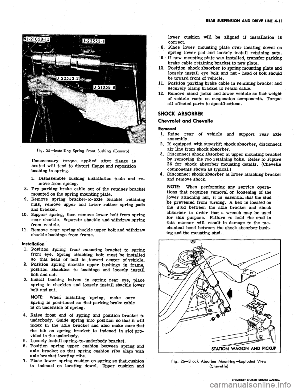
25—Installing Spring Front Bushing (Camaro)
Unnecessary torque applied after flange is
seated will tend to distort flange and reposition
bushing in spring.
i. Disassemble bushing installation tools and re-
move from spring.
8. Pry parking brake cable out of the retainer bracket
mounted on the spring mounting plate.
9. Remove spring bracket-to-axle bracket retaining
nuts,
remove upper and lower rubber spring pads
and bracket.
10.
Support spring, then remove lower bolt from spring
rear shackle. Separate shackle and withdraw spring
from vehicle.
11.
Remove rear spring shackle upper bolt and withdraw
shackle bushings from frame.
Installation
1.
Position spring front mounting bracket to spring
front eye. Spring attaching bolt must be installed
so that head of bolt is toward center of vehicle.
2.
Position spring shackle upper bushings in frame,
position shackles to bushings and loosely install
bolt and nut.
3.
Install bushing halves in spring rear eye, place
spring to shackles and loosely install shackle lower
bolt and nut.
NOTE: When installing spring, make sure
spring is positioned so that parking brake cable
is on underside of spring.
4.
Raise front end of spring and position bracket to
underbody. Guide spring into position so that it will
index in the axle bracket and also make sure that
the tab on spring bracket is indexed in slot pro-
vided in the underbody.
5.
Loosely install spring-to-underbody bracket.
6. Position spring upper cushion between spring and
axle bracket so that spring cushion ribs align with
axle bracket locating ribs.
7.
Place lower spring cushion on spring so that .cushion
is indexed on locating dowel. Upper cushion and
8. Place lower mounting plate over locating dowel on
spring lower pad and loosely install retaining nuts.
9. If new mounting plate was installed, transfer parking
brake cable retaining bracket to new plate.
10.
Position shock absorber to spring mounting plate and
loosely install eye bolt and nut - head of bolt should
be toward front of vehicle.
11.
Position parking brake cable in retaining bracket and
securely clamp bracket to retain cable.
12.
Remove stand jacks and lower vehicle so that weight
of vehicle rests on suspension components. Torque
all affected parts to specifications.
SHOCK ABSORBER
Chevrolet and Chevelle
Removal
1.
Raise rear of vehicle and support rear axle
assembly.
If equipped with superlift shock absorber, disconnect
air line from shock absorber.
Disconnect shock absorber at upper mounting bracket
by removing the two retaining bolts. Refer to Figure
26 for shock absorber mounting details. (Chevelle
components shown as typical.)
Disconnect shock absorber at lower attaching bracket
and remove shock.
NOTE: When performing any service opera-
tions that requires removal or loosening of the
lower attaching nut, it is essential that the stud
be prevented from turning. A hex is located on
the stud between the axle bracket and shock
absorber in order that a wrench may be used
for this purpose. Failure to hold the stud in
this manner will result in damage to the mer
chanical bond between the shock absorber bush-
ing and the mounting stud.
2.
3.
STATION WAGON AND PICKUP
Fig.
26—Shock Absorber Mounting—Exploded View
(Chevelle)
CHEVROLET CHASSIS SERVICE MANUAL
Page 208 of 659
REAR SUSPENSION AND DRIVE LINE 4-18
ig.
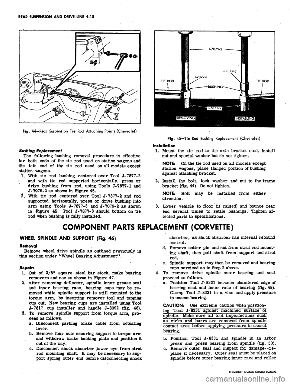
44—Rear Suspension Tie Rod Attaching Points (Chevrolet)
Bushing
Replacement
The following bushing removal procedure is effective
for both ends of the tie rod used on station wagons and
the left end of the tie rod used on all models except
station wagons.
1,
With tie rod bushing centered over Tool J-7877-2
and with tie rod supported horizontally, press or
drive bushing from rod, using Tools J-7877-1 and
J-7079-2 as shown in Figure 45.
2.
With tie rod centered over Tool J-7877-2 and rod
supported horizontally, press or drive bushing into
arm using Tools J-7877-3 and J-7079-2 as shown
in Figure 45. Tool J-7877-3 should bottom on tie
rod when bushing is fully installed.
fig.
45—Tie Rod Bushing Replacement (Chevrolet)
Installation
1.
Mount the tie rod to the axle bracket stud. Install
nut and special washer but do not tighten.
NOTE:
On the tie rod used on all models except
station wagons, place flanged portion of bushing
against attaching bracket.
2.
Install the bolt, lock washer and nut to the frame
bracket (fig. 44). Do not tighten.
NOTE:
Bolt may be installed from either
direction.
3.
Lower vehicle to floor (if raised) and bounce rear
end several times to settle bushings. Tighten af-
fected parts to specifications.
COMPONENT PARTS REPLACEMENT (CORVETTE)
WHEEL SPINDLE AND SUPPORT (Fig. 46)
Removal
Hemdve wheel drive spindle as outlined previously in
this section under "Wheel Bearing Adjustment".
Repairs
Out of 3/8" square steel bar stock, make bearing
removers and use as shown in Figure 47.
After removing deflector, spindle inner grease seal
and inner bearing race, bearing cups may be re-
moved while spindle support is still mounted to the
torque arm, by inserting remover tool and tapping
cup out. New bearing cups are installed using Tool
J-7817 cup installer and handle J-8092 (fig. 48).
To remove spindle support from torque arm, pro-
ceed as follows.
a. Disconnect parking brake cable from actuating
lever.
b.
Remove four nuts securing support to torque arm
and withdraw brake backing plate and position it
out of the way.
c. Disconnect shock absorber lower eye from strut
rod mounting shaft. It may be necessary to sup-
port spring outer end before disconnecting shock
absorber, as shock absorber has internal rebound
control.
d. Remove cotter pin and nut from strut rod mount-
ing shaft, then pull shaft from support and strut
rod.
e. Spindle support may then be removed and bearing
cups serviced as in Step 2 above.
4.
To remove drive spindle outer bearing and seal
proceed as follows.
a. Position Tool J-8331 between chamfered edge of
bearing seat and inner race of bearing (fig. 49).
Clamp Tool J-8331 in a vise and apply pressure
to unseat bearing.
CAUTION: Use extreme caution when position-
ing Tool J-8331 against machined surface of
spindle. Make sure all tool imperfections such
as nicks and burrs are removed from spindle
contact area before applying pressure to unseat
bearing.
b.
Position Tool J-8331 and spindle in an arbor
press and press bearing from spindle (fig. 50).
c. Remove outer seal and inspect for damage--re-
place if necessary. Outer seal must be placed on
spindle before outer bearing inner race and roller
CHEVROLET CHASSIS SERVICE MANUAL
Page 210 of 659
REAR SUSPENSION AND DRIVE LINE 4-20
Fig.
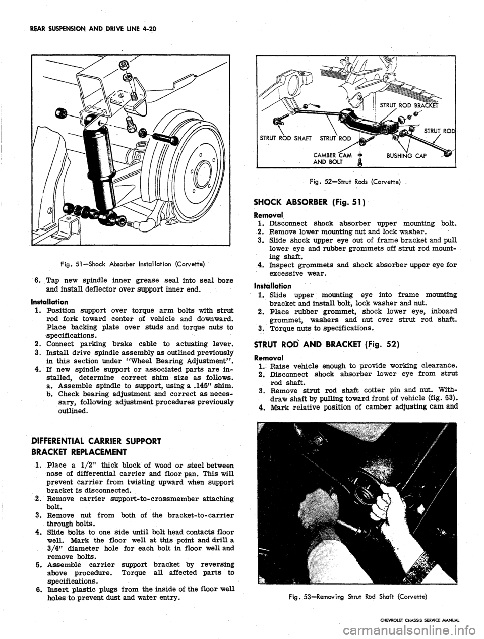
51—Shock Absorber Installation (Corvette)
6. Tap new spindle inner grease seal into seal bore
and install deflector over support inner end.
Installation
1.
Position support over torque arm bolts with strut
rod fork toward center of vehicle and downward.
Place backing plate over studs and torque nuts to
specifications.
2.
Connect parking brake cable to actuating lever.
3.
Install drive spindle assembly as outlined previously
in this section under "Wheel Bearing Adjustment".
4.
If new spindle support or associated parts are in-
stalled, determine correct shim size as follows.
a. Assemble spindle to support, using a .145" shim.
b.
Check bearing adjustment and correct as neces-
sary, following adjustment procedures previously
outlined.
DIFFERENTIAL CARRIER SUPPORT
BRACKET REPLACEMENT
1.
Place a 1/2" thick block of wood or steel between
nose of differential carrier and floor pan. This will
prevent carrier from twisting upward when support
bracket is disconnected.
2.
Remove carrier support-to-crossmember attaching
bolt.
3.
Remove nut from both of the bracket-to-carrier
through bolts.
4.
Slide bolts to one side until bolt head contacts floor
well. Mark the floor well at this point and drill a
3/4"
diameter hole for each bolt in floor well and
remove bolts.
5. Assemble carrier support bracket by reversing
above procedure. Torque all affected parts to
specifications.
6. Insert plastic plugs from the inside of the floor well
holes to prevent dust and water entry.
STRUT ROD SHAFT STRUT ROD
CAMBER CAM
AND BOLT
Fig.
52—Strut Rods (Corvette)
SHOCK ABSORBER (Fig. 51)
Removal
1.
Disconnect shock absorber upper mounting bolt*
2.
Remove lower mounting nut and lock washer.
3.
Slide shock upper eye out of frame bracket and pull
lower eye and rubber grommets off strut rod mount-
ing shaft.
4.
Inspect grommets and shock absorber upper eye for
excessive wear.
Installation
1.
Slide upper mounting eye into frame mounting
bracket and install bolt, lock washer and nut.
2.
Place rubber grommet, shock lower eye, inboard
grommet, washers and nut over strut rod shaft.
3.
Torque nuts to specifications.
STRUT ROD AND BRACKET (Fig. 52)
Removal
1.
Raise vehicle enough to provide working clearance.
2.
Disconnect shock absorber lower eye from strut
rod shaft.
3.
Remove strut rod shaft cotter pin and nut. With-
draw shaft by pulling toward front of vehicle (fig. 53).
4.
Mark relative position of camber adjusting cam and
Fig.
53-Removing Strut Rod Shaft (Corvette)
CHEVROLET CHASSIS SERVICE MANUAL
Page 213 of 659
REAR SUSPENSION AND DRIVE LINE 4-23
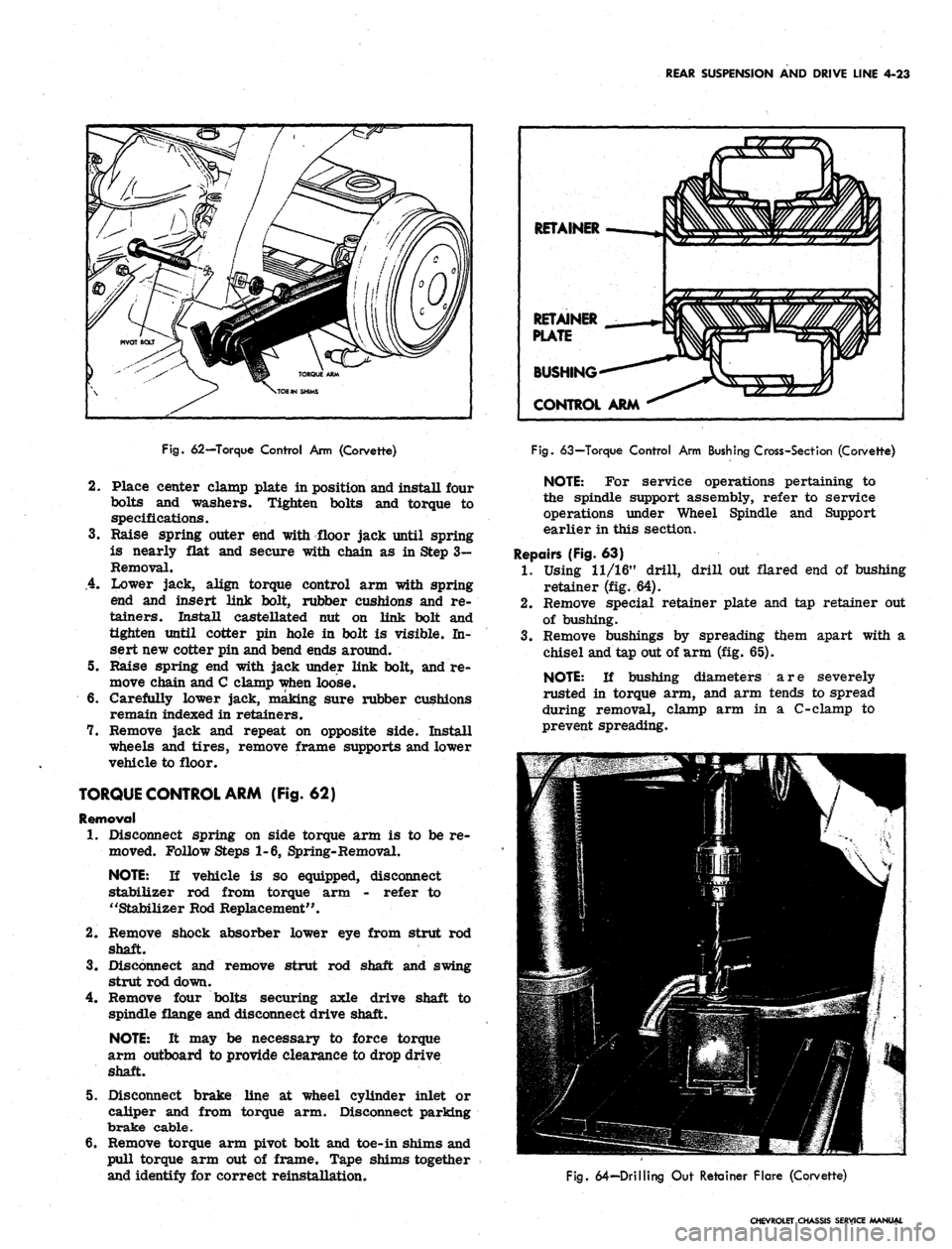
Fig.
62—Torque Control Arm (Corvette)
2.
Place center clamp plate in position and install four
bolts and washers. Tighten bolts and torque to
specifications.
3.
Raise spring outer end with floor jack until spring
is nearly flat and secure with chain as in Step 3-
Removal.
.4.
Lower jack, align torque control arm with spring
end and insert link bolt, rubber cushions and re-
tainers. Install castellated nut on link bolt and
tighten until cotter pin hole in bolt is visible. In-
sert new cotter pin and bend ends around.
5. Raise spring end with jack under link bolt, and re-
move chain and C clamp when loose.
6. Carefully lower jack, making sure rubber cushions
remain indexed in retainers.
7. Remove jack and repeat on opposite side. Install
wheels and tires, remove frame supports and lower
vehicle to floor.
TORQUE CONTROL ARM (Fig. 62)
Removal
1.
Disconnect spring on side torque arm is to be re-
moved. Follow Steps 1-6, Spring-Removal.
NOTE:
If vehicle is so equipped, disconnect
stabilizer rod from torque arm - refer to
"Stabilizer Rod Replacement".
2.
Remove shock absorber lower eye from strut rod
shaft.
3.
Disconnect and remove strut rod shaft and swing
strut rod down.
4.
Remove four bolts securing axle drive shaft to
spindle flange and disconnect drive shaft.
NOTE:
It may be necessary to force torque
arm outboard to provide clearance to drop drive
shaft.
5. Disconnect brake line at wheel cylinder inlet or
caliper and from torque arm. Disconnect parking
brake cable.
6. Remove torque arm pivot bolt and toe-in shims and
pull torque arm out of frame. Tape shims together
and identify for correct reinstallation.
RETAINER
RETAINER
PLATE
BUSHING
CONTROL ARM
Fig.
63—Torque Control Arm Bushing Cross-Sect ion (Corvette)
NOTE:
For service operations pertaining to
the spindle support assembly, refer to service
operations under Wheel Spindle and Support
earlier in this section.
Repairs (Fig. 63)
1.
Using 11/16" drill, drill out flared end of bushing
retainer (fig. 64).
2.
Remove special retainer plate and tap retainer out
of bushing.
3.
Remove bushings by spreading them apart with a
chisel and tap out of arm (fig. 65).
NOTE:
If bushing diameters are severely
rusted in torque arm, and arm tends to spread
during removal, clamp arm in a C-clamp to
prevent spreading.
Fig.
64—Drilling Out Retainer Flare (Corvette)
CHEVROLET CHASSIS SERVICE MANUAL
Page 220 of 659
REAR SUSPENSION AND DRIVE LINE 4-30
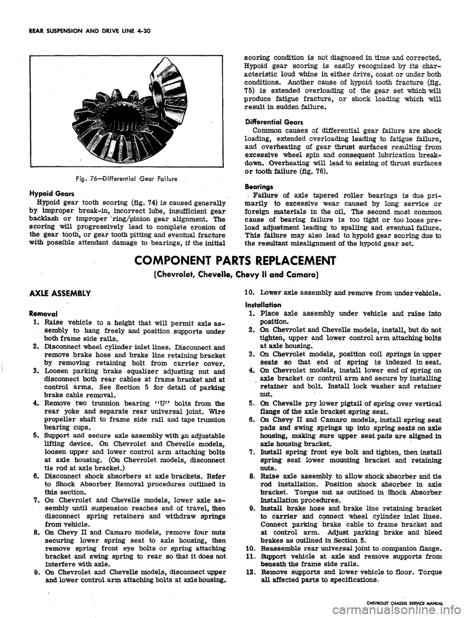
Fig.
76—Differential Gear Failure
Hypoid Gears
Hypoid gear tooth scoring (fig. 74) is caused generally
by improper break-in, incorrect lube, insufficient gear
backlash or improper 'ring/pinion gear alignment. The
scoring will progressively lead to complete erosion of
the gear tooth, or gear tooth pitting and eventual fracture
with possible attendant damage to bearings, if the initial
scoring condition is not diagnosed in time and corrected.
Hypoid gear scoring is easily recognized by its char-
acteristic loud whine in either drive, coast or under both
conditions. Another cause of hypoid tooth fracture (fig.
75) is extended overloading of the gear set which will
produce fatigue fracture, or shock loading which will
result in sudden failure.
Differential Gears
Common causes of differential gear failure are shock
loading, extended overloading leading to fatigue failure,
and overheating of gear thrust surfaces resulting from
excessive wheel spin and consequent lubrication break-
down. Overheating will lead to seizing of thrust surfaces
or tooth failure (fig. 76).
Bearings
• Failure of axle tapered roller bearings is due pri-
marily to excessive wear caused by long service or
foreign materials in the oil. The second most common
cause of bearing failure is too tight or too loose pre-
load adjustment leading to spalling and eventual failure.
This failure may also lead to hypoid gear scoring due to
the resultant misalignment of the hypoid gear set.
COMPONENT PARTS REPLACEMENT
(Chevrolet, Cheveile, Chevy II and Camaro)
AXLE ASSEMBLY
Removal
1.
Raise vehicle to a height that will permit axle as-
sembly to hang freely and position supports under
both frame side rails.
2.
Disconnect wheel cylinder inlet lines. Disconnect and
remove brake hose and brake line retaining bracket
by removing retaining bolt from carrier cover.
3.
Loosen parking brake equalizer adjusting nut and
disconnect both rear cables at frame bracket and at
control arms. See Section 5 for detail of parking
brake cable removal.
4.
Remove two trunnion bearing "U" bolts from the
rear yoke and separate rear universal joint. Wire
propeller shaft to frame side rail and tape trunnion
bearing cups.
5. Support arid secure axle assembly with an adjustable
lifting device. On Chevrolet and Cheveile models,
loosen upper and lower control arm attaching bolts
at axle housing. (On Chevrolet models, disconnect
tie rod at axle bracket.)
6. Disconnect shock absorbers at axle brackets. Refer
to Shock Absorber Removal procedures outlined in
this section.
7. On Chevrolet and Cheveile models, lower axle as-
sembly until suspension reaches end of travel, then
disconnect spring retainers and withdraw springs
from vehicle.
8. On Chevy II and Camaro models, remove four nuts
securing lower spring seat to axle housing, then
remove spring front eye bolts or spring attaching
bracket and swing spring to rear so that it does not
interfere with axle.
9. On Chevrolet and Cheveile models, disconnect upper
and lower control arm attaching bolts at axle housing*
10.
Lower axle assembly and remove from under vehicle.
Installation
1.
Place axle assembly under vehicle and raise into
position.
2.
On Chevrolet and Cheveile models, install, but do not
tighten, upper and lower control arm attaching bolts
at axle housing.
3.
On Chevrolet models, position coil springs in upper
seats so that end of spring is indexed in seat.
4.
On Chevrolet models, install lower end of spring on
axle bracket or control arm and secure by installing
retainer and bolt. Install lock washer and retainer
nut.
5. On Cheveile pry lower pigtail of spring over vertical
flange of the axle bracket spring seat.
6. On Chevy II and Camaro models, install spring seat
pads and swing springs up into spring seats on axle
housing, making sure upper seat pads are aligned in
axle housing bracket.
7. Install spring front eye bolt and tighten, then install
spring seat lower mounting bracket and retaining
nuts.
8. Raise axle assembly to allow shock absorber and tie
rod installation. Position shock absorber in axle
bracket. Torque nut as outlined in Shock Absorber
Installation procedures.
9. Install brake hose and brake line retaining bracket
to carrier and connect wheel cylinder inlet lines.
Connect parking brake cable to frame bracket and
at control arm. Adjust parking brake and bleed
brakes as outlined in Section 5.
10.
Reassemble rear universal joint to companion flange.
11.
Support vehicle at axle and remove supports from
beneath the frame side rails.
12.
Remove supports and lower vehicle to floor. Torque
all affected parts to specifications.
CHEVROLET CHASSIS SERVICE MANUAL
Page 234 of 659
BRAKES
SECTION 5
CONTENTS OF THIS SECTION
Duo Servo Brakes
Disc Brakes
Page
5-1 Power Brakes
5-24 Special Tools
Page
5-31
5-32
DUO-SERVO BRAKES
INDEX
Page
General Description 5-1
Maintenance and Adjustments 5-3
Hydraulic Brake Fluid .. . 5-3
Bleeding Hydraulic System 5-3
Pressure Bleeding 5-3
Manual Bleeding 5_4
Push Rod to Main Cylinder Clearance 5-5
Hydraulic Brake Lines 5-5
Hydraulic Brake Hose 5-5
Hydraulic Brake Tubing 5-6
Brake Adjustment. .................... 5-7
Service Brake 5-7
Parking Brake 5-8
Component Replacement and Repairs 5-9
Parking Brake - Chevrolet, Chevelle and
Camaro 5^9
Pedal Assembly 5-9
Front Cable ,. . . 5-9
Center Cable 5-9
Rear Cables. . 5-9
Parking Brake - Chevy n 5-9
Lever Assembly 5-9
Idler Lever 5-11
Front Cable 5-11
Rear Cable . . ; 5-12
Parking Brake - Corvette 5-13
Lever Assembly . . . . 5-13
Front Cable 5-14
Rear Cable . . 5-14
Brake Pedal 5-15
Shoes and Linings 5-16
Organic 5-16
Metallic 5-17
Main Cylinder 5-18
Wheel Cylinders 5-21
Anchor Pin 5-22
Front Wheel 5-22
Rear Wheel 5-22
Brake Drums • 5-22
Brake Pipe Distribution and Switch Assembly . . . . . 5-23
Camaro Pressure Regulator Valve 5-23
GENERAL DESCRIPTION
All 1967 models are equipped with a new split brake
system as a safety feature. If a wheel cylinder or brake
line should fail at either the front end or rear end of
the vehicle, the operator can still bring the vehicle to
a controlled stop. The system is designed with separate
hydraulic systems for the front and rear brake using
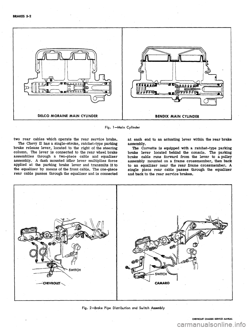
a dual master cylinder (fig. 1). The design of the master
cylinder is similar to that used on the 1966 Corvette
in that it has two entirely separate reservoirs and outlets
in a common body casting. The front reservoir and outlet
is connected to the front wheel brakes, and the rear
reservoir and outlet is connected to the rear wheel
brakes. Two pistons within the master cylinder receive
mechanical pressure from the brake pedal push rod and
transmit it through the brake lines as hydraulic pressure
to the wheel cylinders. The filler cap is accessible from
inside the engine compartment.
A new brake pipe distribution and switch assembly
is mounted below the main cylinder. The front and rear
hydraulic brake lines are routed from the main cylinder,
through the brake pipe distribution and switch assembly,
to the front and rear brakes as shown in Figure 2. The
switch is wired electrically to the brake alarm indicator
light on the instrument panel. In the event of fluid loss
in either the front or rear brake system the indicator
on the instrument panel will illuminate red. (The indi-
cator will also' be illuminated when the parking brake is
applied.)
On Camaro models equipped with air conditioning, the
rear brake hydraulic line is routed through a pressure
regulator valve mounted on the left frame side rail
(fig. 3). The valve controls the hydraulic pressure to
the rear brakes resulting in the correct pressure balance
between the front and rear hydraulic systems.
The self-adjusting brakes (fig. 4), used on both front
and rear of all models, are the Duo-Servo single anchor
type which utilize the momentum of the vehicle to assist
in the brake application. The self-energizing or
self-
actuating force is applied to both brake shoes at each
wheel in both forward and reverse motion. The brake
shoe linings are bonded to the shoes.
Wheel cylinders are the double piston type permitting
even distribution of pressure to each brake shoe. To
keep out dust and moisture, both ejads of each wheel
cylinder are sealed with a rubber booC The wheel
cylinders have no adjustments.
The Chevrolet, Chevelle, and Camaro parking brakes
have a foot operated ratchet type pedal mounted to the
left of the steering column. A cable assembly connects
the pedal to an intermediate cable by means of an equal-
izer, where the adjustment for the parking brake is
incorporated. The intermediate cable attaches to the
CHEVROLET CHASSIS SERVICE MANUAL
Page 235 of 659
BRAKES 5-2
DELCO MORAINE MAIN CYLINDER
BENDIX MAIN CYLINDER
Fig.
I—Main
Cylinder
two rear cables which operate the rear service brake.
The Chevy II has a single-stroke, ratchet-type parking
brake release lever, located to the right of the steering
column. The lever is connected to the rear wheel brake
assemblies through a two-piece cable and equalizer
assembly. A dash mounted idler lever multiplies force
applied at the parking brake lever and transmits it to
the equalizer by means of the front cable. The one-piece
rear cable passes through the equalizer and is connected
at each end to an actuating lever within the rear brake
assembly.
The Corvette is equipped with a ratchet-type parking
brake lever located behind the console. The parking
brake cable runs forward from the lever to a pulley
assembly mounted on a frame crossmember, then back
to an equalizer near the rear frame crossmember. A
single piece rear cable passes through the equalizer
and back to the rear service brakes.
— CHEVROLET
CAMARO
Fig.
2—Brake Pipe Distribution and Switch Assembly
CHEVROLET CHASSIS SERVICE MANUAL
Page 241 of 659
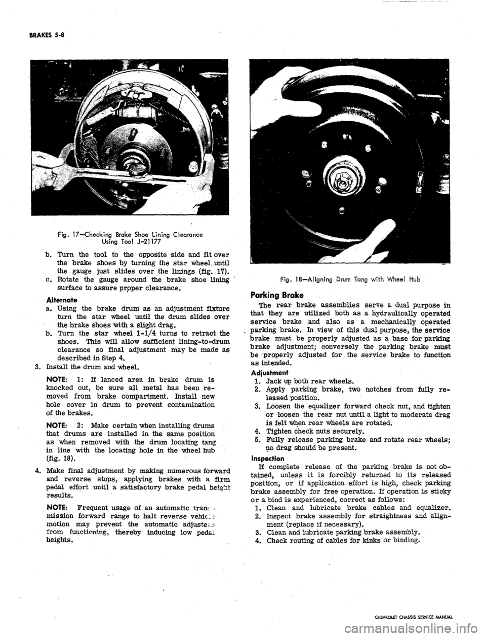
BRAKES 5-8
Fig.
17—-Checking Brake Shoe Lining Clearance
Using Tool J-21177
b.
Turn the tool to the opposite side and fit over
the brake shoes by turning the star wheel, until
the gauge just slides over the linings (fig. 17).
c. Rotate the gauge around the brake shoe lining
surface to assure prpper clearance.
Alternate
a. Using the brake drum as an adjustment fixture
turn the star wheel until the drum slides over
the brake shoes with a slight drag.
b.
Turn the star wheel 1-1/4 turns to retract the
shoes.
This will allow sufficient lining-to-drum
clearance so final adjustment may be made as
described in Step 4.
3.
Install the drum and wheel.
NOTE: 1: If lanced area in brake drum is
knocked out, be sure all metal has been re-
moved from brake compartment. Install new
hole cover in drum to prevent contamination
of the brakes.
NOTE: 2: Make certain when installing drums
that drums are installed in the same position
as when removed with the drum locating tang
in line with the locating hole in the wheel hub
(fig. 18).
4.
Make final adjustment by making numerous forward
and reverse stops, applying brakes with a firm
pedal effort until a satisfactory brake pedal height
results.
NOTE: Frequent usage of an automatic trans-
mission forward range to halt reverse vehic;..$
motion may prevent the automatic adjuster.:?
from functioning, thereby inducing low pedal
heights.
Fig.
.18—Aligning Drum Tang with Wheel Hub
Parking Broke
The rear brake assemblies serve a dual purpose in
that they are utilized both as a hydraulically operated
service brake and also as a mechanically operated
parking brake. In view of this dual purpose, the service
brake must be properly adjusted as a base for parking
brake adjustment; conversely the parking brake must
be properly adjusted for the service brake to function
as intended.
Adjustment
1.
Jack up both rear wheels.
2.
Apply parking brake, two notches from fully re-
leased position.
3.
Loosen the equalizer forward check nut, and tighten
or loosen the rear nut until a light to moderate drag
is felt when rear wheels are rotated.
4.
Tighten check nuts securely.
5.
Fully release parking brake and rotate rear wheels;
no drag should be present.
Inspection
If complete release of the parking brake is not ob-
tained, unless it is forcibly returned to its released
position, or if application effort is high, check parking
brake assembly for free operation. If operation is sticky
or a bind is experienced, correct as follows:
1.
Clean and lubricate brake cables and equalizer.
2.
Inspect brake assembly for straightness and align-
ment (replace if necessary).
3.
Clean and lubricate parking brake assembly.
4.
Check routing of cables for kinks or binding.
CHEVROLET CHASSIS SERVICE MANUAL
Page 242 of 659
BRAKES 5-9
COMPONENT REPLACEMENT AND REPAIRS
PARKING BRAKE-CHEVROLET, CHEVELLE AND
CAMARO (Figs. 19 and 20)
Pedal Assembly
Removal
NOTE:
Remove positive cable from battery to
eliminate the possibility of creating short cir-
cuits under dash.
1.
Place parking brake pedal in released position.
2.
Remove equalizer check nut, and separate cable
stud from equalizer.
3.
Remove two attaching nuts from mounting studs
located in engine compartment.
4.
Remove front cable .ball end from pedal assembly
swivel.
5. Remove pedal assembly to dash brace attaching
screw.
6. Remove pedal assembly by lowering rear slightly
to avoid scratching dash, and pulling, it out of the
firewall.
Installation
1.
Place pedal assembly in position with the two mount-
ing studs protruding through the holes provided in
the firewall.
2.
Install and tighten pedal assembly to dash brace
attaching screw.
3.
Position front cable ball end into pedal assembly
swivel.
4.
Install and tighten two attaching nuts on mounting
studs located in engine compartment.
5. Place
,
equalizer in position on center cable and
insert front cable stud through equalizer and secure
with check nut.
6. Adjust parking brake as outlined under Maintenance
and Adjustments in this section.
7. Connect positive battery cable.
Front Cable
Removal
NOTE:
Remove positive cable from battery to
eliminate the possibility of creating short cir-
cuits under dash.
1.
Place parking brake pedal in released position.
2.
Remove equalizer check nut, and separate cable
, stud from equalizer.
3.
Remove retainer from cable assembly at inner side
of frame rail.
4.
Remove ball end of cable from pedal assembly
swivel.
5. Compress expanded conduit locking fingers at toe
pan arid withdraw cable from car.
6. On Chevelle, if necessary, remove rubber tube
from front cable.
Installation
1.
On Chevelle, if necessary, replace rubber tube
over front cable.
2.
Position cable ball and conduit tip through cutout
in firewall. Make sure conduit locking fingers are
fully expanded and secured in cutout, then position
cable ball into pedal assembly swivel.
3.
Feed stud end of cable through frame rail and se-
cure with retainer on inner side of frame.
4.
Place one check nut on cable stud and insert stud
through equalizer, (make sure center cable is in
position), then place second check nut on stud.
5. Adjust parking brake as outlined in this section.
6. Connect positive battery cable.
Center Cable
Removal
1.
Place parking brake pedal in released position.
2.
Remove equalizer check nut and remove equalizer
from cable.
3.
Remove cable from cable guides.
4.
Disconnect center cable from rear cables at
connectors.
Installation
1.
Install cable ends into rear cable connectors.
2.
Place cable through equalizer and install equalizer
on to front cable stud, secure with check nut. (Do
not tighten.)
3.
Install cable in cable guides (figs. 19 and 20),
4.
Adjust parking brake as outlined in this section.
Rear Cables
Removal
1.
Place parking brake pedal in released position.
2.
Remove equalizer check nut and remove equalizer
from cable.
3.
Remove rear cable from connector.
4.
Remove retainer from rear cable at frame bracket.
Pull cable out of bracket.
5. Remove rear brake drum as outlined in this section.
6. Remove rear brake shoes as outlined in this section.
7. Remove cable end from parking brake actuating
lever.
8. Compress expanded conduit locking fingers at flange
plate entry hole and withdraw cable.
Installation
1.
Pass end of cable and conduit tip through flange
plate entry hole, making sure that conduit locking
fingers all expand fully.
2.
Connect cable end to actuating lever.
3.
Install rear brake shoes, drum and wheel as out-
lined in this section.
4.
Pass cable through frame bracket and install
retainer.
5. Install cable end into cable connector.
6. Position equalizer on center cable and place on
front cable stud, secure with check nut.
7. Make sure all center cable guides are in place
and adjust parking brake as outlined in this section.
PARKING BRAKE-CHEVY II (Fig. 21)
Lever Assembly
Removal
NOTE:
Remove positive cable from battery
to eliminate possibility of creating short cir-
cuits under dash.
CHEVROLET CHASSIS SERVICE MANUAL